PDF Download: [CA1228833A1-Gas\_Electrical\_Hydrogen\_Generator.pdf](http://stanslegacy.com/attachments/5)
> (51) INT. CL. C25B 1/04 Consumer and Consommation Corporate Affairs Canada et Corporations Canada > (11) (A) No. 1 228 833 > (45) ISSUED 871103 > (52) CLASS 204-152 C.R. CL. 322-1as) ca) CANADIAN PATENT «2 > (54) Gas Electrical Hydrogen Generator > {72) Meyer, Stanley A.,U.S.A. > {21) APPLICATION No. (22) FILED > (30) PRIORITY DATE > DISTRIBUTED BY THE PATENT OFFICE, OTTAWA. CCA-274 {11-82) C-2388 #### Illustrations| [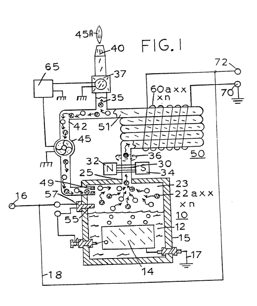](http://stanslegacy.com/uploads/images/gallery/2022-06/h2snHw4KdVGSi3Ps-screenshot-from-2022-06-23-10-54-04.png) | [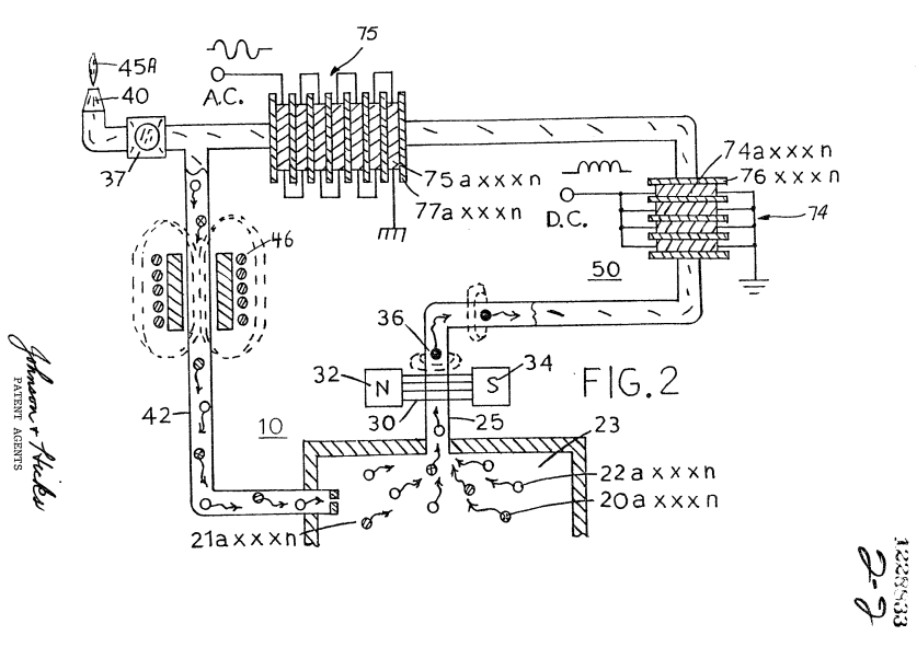](http://stanslegacy.com/uploads/images/gallery/2022-06/COvSi5xtxP3MLvor-screenshot-from-2022-06-23-10-48-13.png) |
Further, it has been found that the increase in pressure of the gases in chamber 23 increases the velocity of the gas exponentially. Simply, an arithmetical increase in pressure of the gases released results in a geometrical increase in frequency and amplitude of the output voltage from either the direct current winding 74 or the alternating current winding 75.
There will be instances where an increase in velocity (pressure) is needed to increase the output voltage of the electrical generator but the generation of more hydrogen gas may be undesirable. That is, for instance when’the flame 45A is a con- trolled gas mixture flame. The addition of more hydrogen will increase the temperature of the combustibility of the mixture and will increase its velocity. The utility of the flame, if not quenched, will be affected proportionately.Accordingly, to increase the gas pressure in chamber 23 **other non-combustible gasses** 2la xxx n, such as **nitrogen** are added via pressure inlet means to the mixture.
Although certain and specific embodiments are shown and described, alternatives and modifications may be had without departing from the spirit and scope of the invention. ##### THE EMBODIMENTS OF THE INVENTION IN WHICH AN EXCLUSIVE PROPERTY OR PRIVILEGE IS CLAIMED ARE DEFINED AS FOLLOWS: 1\. Apparatus comprising: > a housing having a water reservoir for retaining water therein and a gas collection chamber; > > a pair of similar non-oxidizing exciter elements positioned in said water reservoir and adapted to be connected to a voltage potential that creates a negative charge on one of the exciter elements and a positive charge on the other and thereby release gases including hydrogen and oxygen from water in the reservoir; > > a non-magnetic tubing connected at one end to said collection chamber via an outlet therefrom; > > a magnetic polarizer positioned for magnetically charging gas flowing through said tubing; and an inductive winding positioned over said tubing downstream from said polarizer whereby flux lines of magnetized gas passing through said tubing and traversing said inductive winding induce a current/voltage in said inductive winding. 2\. The apparatus of Claim 1 further comprising: gas utilization means connected to the other end of said tubing for utilizing said generated hydrogen/oxygen gas mixture. 3\. The apparatus of Claim 1 further comprising: > a nozzle connected to the other end of said tubing, > > said nozzle having a port of pre-determined size and configuration through which the gases are expelled, and means for igniting said gases. 4\. The apparatus of Claim 1 further comprising: control means for maintaining a predetermined gas pressure in said collection chamber. 5\. The apparatus of Claim 1 further comprising: > a pressure gauge for determining the pressure in said collection chamber, and > > switch means for controlling the voltage potential source to terminate the generation of hydrogen/oxygen gases upon said collection chamber attaining a predetermined pressure. 6\. The apparatus of Claim 1 further comprising: a gas line tubing connected to the other end of said non-magnetic tubing and to said collection chamber in a closed loop arrangement. 7\. The apparatus of Claim 1 further comprising: a gas line tubing connecting the other end of said non-magnetic tubing to said collection chamber in a closed loop arrangement, and means in said gas line tubing for maintaining said polarized hydrogen and oxygen atoms circulating through said non-magnetic tubing. 8\. The apparatus of Claim 1 further comprising: a gas line tubing connected to the other end of said non-magnetic tubing *and* to said collection chamber in a closed loop arrangement, and a unidirectional valve connected to the end of said gas line tubing connected to said collection chamber. 9\. The apparatus of Claim 1 further comprising: a gas line tubing and gas utilization means, a Y-type connector for alternately connecting said gas line tubing to said gas utilization means and said collection chamber in a closed loop arrangement. 10\. The apparatus of Claim 1 further comprising: a gas line tubing and gas utilization means, a Y-type connector for alternately connecting said gas line tubing to said gas utilization means said collection chamber in a closed loop arrangement, two directional valve means, and a demand circuit connected to said valve means for selectively connecting said gas line tubing to said gas utilization means or said collection chamber in response to pre-determined conditions. ll. An apparatus comprising: a gas generator housing having a gas collection chamber for maintaining a preset volume of gas therein under pressure, outlet means from said gas collection chamber, a non-magnetic tubing connected to said outlet means, a magnetic polarizer positioned adjacent said outlet means between said chamber and said tubing for magnetically charging gas expelled from said chamber through said outlet means, and an inductive coil positioned over said non-magnetic tubing whereby the flux lines of magnetized gas passing through said tubing and traversing said inductive coil, induce a current/voltage therein. 12\. The apparatus of Claim 11 wherein: said gas is a combustible gas, and utilization means connected to the opposite end of said non-magnetic tubing for utilizing said gases. 13\. The apparatus of Claim 11 wherein: said coil comprises a plurality of windings wound in parallel, and wherein said induced voltage/current therein is of a single polarity. 14\. The apparatus of Claim 11 wherein: > said coil comprises a plurality of windings connected in series polarity. 15\. The apparatus of Claim 11 wherein: > said coil comprises a plurality of windings and wherein the number of said plurality of windings is determinative of the frequency of the said induced voltage/current therein. 16\. The apparatus of Claim 11 further comprising: means for varying the pressure of said gas in said collection chamber to vary the output frequency of said induced voltage in said coils. 17\. The apparatus of Claim 11 further comprising: means for varying the generation of said gas to vary the pressure of said gas in said collection chamber to vary the output frequency of said induced voltage in said coils. 18\. The apparatus of Claim 11 further comprising: > means for adding non-combustible gases to said collection chamber to vary the pressure of said gas in said collection chamber to vary the output frequency of said induced voltage in said coils. 19\. The apparatus of Claim 11 wherein: > said non-magnetic tubing further comprises means connected thereto for returning said magnetized gas to said collection chamber, and means for recirculating said gas through said chamber, said non-magnetic tubing and said last named means. 20\. The apparatus of Claim 11 wherein: > said non-magnetic tubing further comprises means connected thereto for returning said magnetized gas to said collection chamber, a particle accelerator for recirculating said gas through said chamber, said tubing, and said last named means. 21\. Apparatus comprising: > a closed vessel suitable for maintaining a volume of water therein, and permitting the addition of water thereto; > > a pair of electrically conductive exciter elements formed of a same non-reactive material located in said vessel in a predetermined spatial relationship to one another and adapted to be connected to a source of a voltage potential that creates a potential difference between an arbitrary electrical ground and the source output with one of said exciter elements being connected to said arbitrary electrical ground and the other of said exciter. elements being connected to said source output, whereby there is formed a nominally positive electrical voltage zone in water adjacent said exciter element connected to said output and a nominally negative voltage zone in water adjacent said exciter element connected to said electrical ground as the voltage potential is applied thereto to a degree such that the hydrogen atoms and the oxygen atoms disassociate from water molecules in the vessel and are released in the form of a gas mixture; > > a gas collection chamber for maintaining a volume of said gas released from water when in the vessel and a potential difference is applied to said exciter elements; > > a non-magnetic tubing connected at an outlet from said collection chamber; > > a magnetic polarizer positioned adjacent the end of said tubing as the gas is expelled from said outlet; and an inductive winding positioned over said tubing wherein flux lines of the magnetized gas passing through said tubing, traverse said inductive winding and induce a current in said inductive winding. # CA1235669A1 Controlled Hydrogen Gas Flame**PDF Download:** [SMeyer-CA1235669A1-Controlled\_Hydrogen\_Gas\_Flame.pdf](http://stanslegacy.com/attachments/9)
> Consumer and Consornmation aS Corporate Affairs Canada el Corporations Canada > > (11) (A) No. 1 235 669 > (45) ISSUED 880426 > (52) CLASS 204-78 C.R. CL. 204-1664 > (51) INT. CL. c25B 1/04us ca GANADIAN PATENT «2 > (54) Controlled Hydrogen Gas Flame > (72) Meyer, Stanley A.,U.S.A. > (21) APPLICATION No. 420,890 > (22) FILED 830204 > (30) PRIORITY DATE U.S.A. (411,977) 820825 No. OF CLAIMS 9 > > Canada > DISTRIBUTED BY THE PATENT OFFICE, OTTAWA, CCA-274 (11-82) VX #### Illustrations| [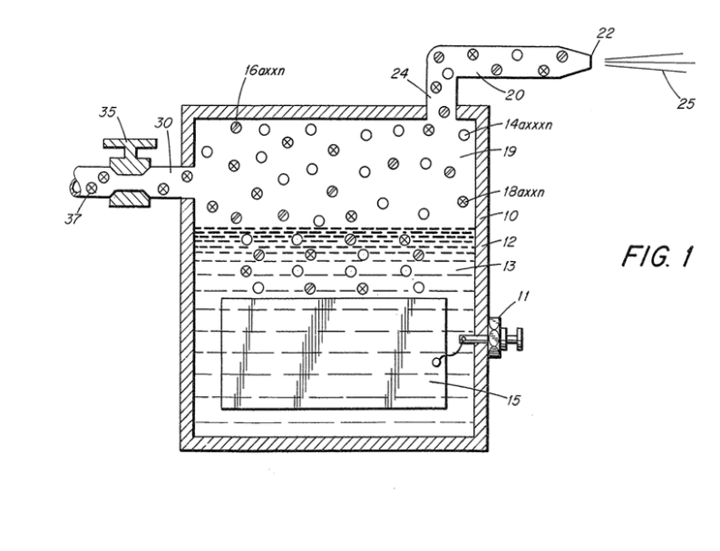](http://stanslegacy.com/uploads/images/gallery/2022-06/C8dIULi2BKjwu6wY-image-1656375633551-20-31.png) | [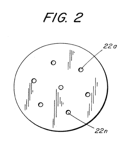](http://stanslegacy.com/uploads/images/gallery/2022-06/yM1i607PuVo5cauB-image-1656375620401-20-17.png) |
This invention relates to apparatus for generating gases from water and for the controlled burning of such generated gases.
The present invention utilizes the hydrogen/oxygen generator disclosed and claimed in my co-pending Canadian Patent Application Serial No. 420,908 filed 4 February, 1983 and entitled "**HYDROGEN GENERATOR SYSTEM**".
In the process disclosed in said application for separating hydrogen and oxygen atoms from water having impurities, water is passed between two plates of similar non-oxidizing metal. No electrolyte is added to the water. The one plate has placed thereon a positive potential and the other a negative potential from a very low amperage direct— current power source. The action of the direct current voltage on the non-electrolytic water causes the hydrogen and oxygen atoms to be separated and also released are other gases entrapped in the water such as nitrogen. Contaminants in the water that are not released as gases are forced to separate from the water and may be collected or utilized and disposed of in a Known manner. Direct current acts as a static force on the water molecules and a non-regulated rippling direct current acts as a dynamic force. Pulsating the direct current further enhances the release of the hydrogen and oxygen atoms from the water molecules, The electrolysis process for generating hydrogen and oxygen gas from water is well known in the art. It is, of course, further understood with a proper mixture of oxygen gas, the hydrogen gas is combustible and under ideal conditions a flame, may be had. Reference is made to U.S. Patent 4,184,921. However, in that the burning velocity of hydrogen is so great (265-325 cm./sec. versus 37-45 cm./sec. for gasoline) the hydrogen ensuing from a nozzle will not under ordinary circumstances sustain a flame.Therefore, to sustain a flame at a nozzle attached to a hydrogen generator the burning velocity of the hydrogen gas must be reduced.
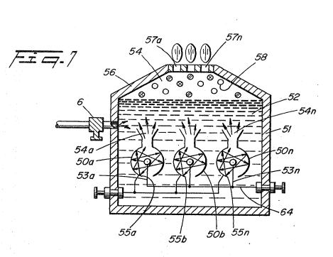
It has been found that all water in its natural state whether it be tap water, well water, sea water, or fresh water is a saturate of ambient air. Further, in that ambient air contains a substantial amount of nitrogen, all natural water will have entrapped therein nitrogen. Again, the percentage of nitrogen entrapped in natural water has been determined to be a fixed percentage and very uniform irrespective of the source of the water or its impurities. A principal object of the present invention is to provide a new and improved hydrogen/oxygen generator that is operable from a water source that provides hydrogen/oxygen output that will have a sustained burn. Another object of the present invention is to provide a hydrogen/oxygen generator that in addition to the hydrogen and oxygen gases releases non-combustible nitrogen gas capable of reducing the burning velocity and temperature of a pure hydrogen/oxygen flame. A further object of the present invention is to provide a hydrogen generator that includes the controlled addition of other non-combustible gases to the gas chamber thereof to thereby further control the burning velocity and temperature of the hydrogen gas. In accordance with the present invention a nozzle is connected to a gas collection chamber via an appropriate line and has a port opening of a controlled size and configuration, related to the size of the flame and the temperature and velocity of the burning gas mixture. To maintain the flame, i.e. prevent blowout, additional nozzles are included when the overall flame size is to be increased. More particularly there is provided in accordance with the present invention an apparatus for generating gases from water and for the controlled burning of the gases generated thereby comprising: > a housing having a chamber for containing natural water therein including entrapped non-combustible gases; > > a pair of similar non-oxidizing electrodes in said chamber and adapted to be connected to a source of rippling wave form direct current voltage in which the current flow is restricted to provide a force action on water in said chamber, which liberates the hydrogen atoms and oxygen atoms from said water as well as non-combustible gases dissolved in said water and thereby producing a mixture of hydrogen, oxygen and non— combustible gases; > > a gas collection chamber in said housing for collecting and intermixing said released gases; and > > a nozzle attached to the gas collection chamber of said housing including an inlet for receiving said mixture of hydrogen, oxygen and non-combustible gases; > > said nozzle having a port of predetermined size and configuration for expelling said mixed gases at a rate so as to sustain a flame from the gases that are liberated from the water. #### Description Of Drawings: The invention is illustrated by way of example in the accompanying drawings wherein: Figure 1 is a cross-sectional view of a hydrogen generator illustrating the features of the present invention in. its most preferred embodiment incorporated therein; and [](http://stanslegacy.com/uploads/images/gallery/2022-06/C8dIULi2BKjwu6wY-image-1656375633551-20-31.png) Figure 2 is a front face view of a nozzle having increased number of nozzle ports to increase the flame size. [](http://stanslegacy.com/uploads/images/gallery/2022-06/yM1i607PuVo5cauB-image-1656375620401-20-17.png) Referring to the drawings the hydrogen generator 10 is the subject of my aforementioned co-pending application Serial No. 420,908. The generator 10 comprises a closed watertight housing 12 having a quantity of natural water 13 in the bottom thereof. Submerged in the water 13 is a pair of plates 15 (one not shown) which have a direct current low amperage voltage, applied thereto via connector 11 during operation. As get forth in my co-pending patent application supra, the electrical potential applied to the similar non-oxidizing metal plates is a sub-atomic action. In this way the hydrogen atoms 14 a xxx n and the oxygen atoms 18 a xxx n are released from the water molecule. Unlike the electrolysis process for generating hydrogen from distilled water, the hydrogen generator of my aforementioned patent application, utilizes water 13 that need not be pure --~ simply any water irrespective of contaminants and source. Natural water such as tap, well, sea, or fresh water is an absorber of ambient air and since ambient air contains a substantial amount of nitrogen gas so does the natural water with the ambient air absorbed therein. In operation of the hydrogen generator, the gases released from natural water are thus nitrogen, hydrogen and oxygen. In the preferred embodiment utilizing tap water, the nitrogen gasses 16 a xxx n are intermixed with the hydrogen gases 14 a xxx n and the oxygen gases 18 a xxx n in the chamber 19 of the hydrogen generator 10. Upon release of the gases via line 24 and nozzle 20 and then port 22 the gas mixture is ignited to provide flame 25. The flame 25 is sustained in that the nitrogen gases 16 a xxx n reduces the burning velocity and temperature of the hydrogen gas 14 a Xxx Nn. A realistic and practical manner of further controlling the burning velocity and temperature of the hydrogen gases 14 a xxx n, is by adding non-combustible gases directly to the hydrogen and oxygen gases generated. This is accomplished by inlet 30 to the upper gas chamber 19 of the hydrogen generator. Valve means 35 is adjustable to control the amount of non- combustible gases 37, added to the gas chamber 19. The nozzle 20 connected to the chamber 19 of the generator 10 via line 17, is of a given configuration to permit a predetermined quantity of gases to be expelled from the port 22. The port size is dependent on the gases generated, and collected in the chamber 19, the pressure of the chamber 19 of the generator 10, and the size of the flame desired. To increase the size of the flame 25 would appear to be a simple matter of increasing the rate of gases generated. However, an increase of gases merely causes a blowout at the port or opening 22 of the nozzle 20. This flame blowout will occur since an increase in hydrogen gas generation disrupts the ratio of the initial mixture even though the percentages remain constant. Typically, tap water contains known percentages of hydrogen, oxygen, and nitrogen. The percentages vary somewhat dependent on the other gases that may be trapped in the tap water. The increase in production will not affect the percentages but it must be appreciated that the volume of the gases will be proportionately increased. In turn, the volume being directly related to pressure, the pressure will be similarly increased. [](http://stanslegacy.com/uploads/images/gallery/2022-06/yM1i607PuVo5cauB-image-1656375620401-20-17.png)To effectively reduce or counteract the velocity due to the increased pressure of the hydrogen gas mixture in the chamber 19 a large port 22 would appear to be capable of handling the increased pressure, but as aforesaid, a larger port with a high velocity hydrogen gas mixture will cause a flame blowout. To sustain a larger flame with increased pressure, additional nozzles having ports 22 **a xxx n** or, a nozzle 20 with multiple ports **22 a xxx** n as shown in Figure 2, can be used. The larger the desired flame the greater will be the number of ports required. It can be understood that a port that will not 5 sustain a flame does present a safety factor relative to hydrogen spark back to the chamber 19. Hence, controlling the size of the port 22 in effect provides a quencher of hydrogen spark back.Although certain and specific embodiments are shown and described it is within the scope and spirit of the present invention to include alternatives and modifications thereto.
##### THE EMBODIMENTS OF THE INVENTION IN WHICH AN EXCLUSIVE PROPERTY OR PRIVILEGE IS CLAIMED ARE DEFINED AS FOLLOWS: 1\. An apparatus for generating gases from water and for the controlled burning of the gases generated thereby comprising: > a housing having a chamber for containing natural water therein including entrapped non-combustible gasses; > > a pair of similar non-oxidizing electrodes in said chamber and adapted to be connected to a source of rippling wave form direct current voltage in which the current Flow is restricted to provide a force action on water in said chamber, which liberates the hydrogen atoms and oxygen atoms from said water as well as non-combustible gases dissolved in said water and thereby producing a mixture of hydrogen, oxygen and non-combustible gases; > > a gas collection chamber in said housing for collecting and intermixing said released gases; and > > a nozzle attached to the gas collection chamber of said housing including an inlet for receiving said mixture of hydrogen, oxygen and non-combustible gases; > > said nozzle having a port of predetermined size and configuration for expelling said mixed gases at a rate so as to sustain a flame from the gases that are liberated from the water. > > 2\. The apparatus of Claim 1 including means for separately introducing non-combustible gases to said gas collection chamber. 3\. The apparatus of Claim 2 including valve means for controlling the amount of non-combustible gases introduced into said chamber. 4\. The apparatus of Claim 1 wherein said nozzle has a plurality of separate ports to thereby control the flame. 5\. A method of producing a combustible gaseous mixture and sustaining controlled burning thereof comprising: (a) providing a quantity of water in a water holding chamber having a pair of similar non-oxidizing electrodes therein; (b) applying a rippling wave form electric potential across said electrodes without any change of polarity and limiting the current flow so as to liberate hydrogen atoms and oxygen atoms from the water molecules as well as non-combustible gases dissolved in the water and thereby provide combustible and non-combustible gases; (c) collecting and intermixing said gases; and (ad) providing a nozzle having at least one port of predetermined size and configuration such that the gaseous mixture flows therethrough at a rate so as to sustain a flame. 6\. The method of Claim 5 including the step of burning said gaseous mixture at said nozzle port. 7\. The method of Claims 5 or 6 including the step of adding further non-combustible gases to said intermixed gases to provide a combustible gas mixture with a selected burn rate. 8\. The method of Claim 7 including the step of burning said gaseous mixture at said nozzle port. 9\. The method of Claims 7 or 8 including the step of adding further non-combustible gases to said intermixed gases to provide a combustible gas mixture with a selected burn rate. # CA2067735A1 Water Fuel Injection System**PDF Download**: [SMeyer-CA2067735A1-Water\_Fuel\_Injection\_System.pdf](http://stanslegacy.com/attachments/10)
> Consommation et Corporations Canada > > Bureau des brevets Ottawa, Canada K1A 0C9 > > Consumer and Corporate Affairs Canada > > Patent Office > (21) (Al) 2,067,735 > (22) 1991/05/17 > (43) 1992/11/185 > (51) INTL.CL. CO1B~-003/04 > (19) (cA) APPLICATION FOR CANADIAN PATENT (12) > (54) Water Fuel Injection System > (72) Meyer, Stanely A. - U.S.A. j; > (73) Same as inventor > (57) 13 Claims > > Notice: The specification contained herein as filed 78/e‘Geo’s CCA 3254 (10-89) 41 2067735 ### ABSTRACT An injector system comprising an -improved method and apparatus useful in the production of a hydrogen containing fuel gas from water in a process in which the dielectric property of water and/or a mixture of water and other components determines a resonant condition that produces a breakdown of the atomic bonding of atoms in the water molecule. The injector delivers a mixture of water mist, ionized gases and non-combustible gas to a zone or locus within which the breakdown process leading to the release of elemental hydrogen from the water molecules occurs. ##### ##### Illustrations| [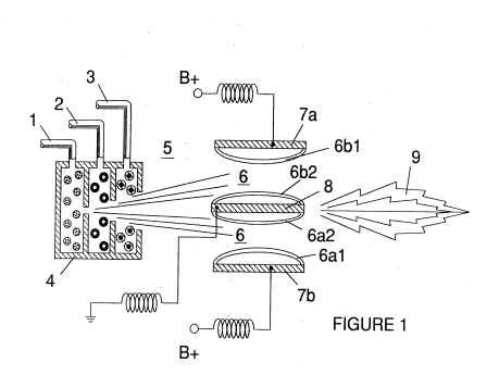](http://stanslegacy.com/uploads/images/gallery/2022-06/BPxw6tWgQ4t6K4fE-screenshot-from-2022-06-25-16-06-25.png) | [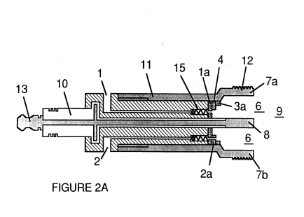](http://stanslegacy.com/uploads/images/gallery/2022-06/jbbljOtNrspzQXLs-screenshot-from-2022-06-25-16-06-31.png) | [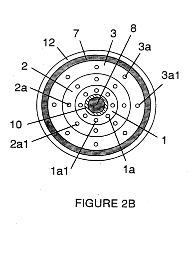](http://stanslegacy.com/uploads/images/gallery/2022-06/HCagrcMh2x9XfZlk-screenshot-from-2022-06-25-16-07-16.png) |
| [](http://stanslegacy.com/uploads/images/gallery/2022-06/BKlT18F8VbG4FkpB-screenshot-from-2022-06-25-16-07-47.png) | [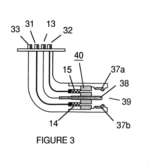](http://stanslegacy.com/uploads/images/gallery/2022-06/Xobr5XjZEJA3p3K0-screenshot-from-2022-06-25-16-06-42.png) | [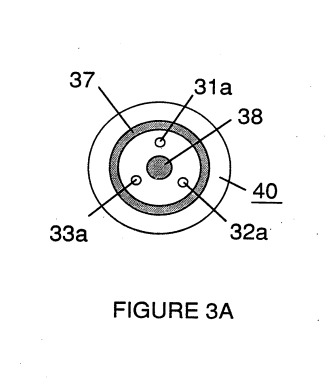](http://stanslegacy.com/uploads/images/gallery/2022-06/gI1VIukimfS7SEY0-screenshot-from-2022-06-25-16-07-31.png) |
| [](http://stanslegacy.com/uploads/images/gallery/2022-06/ulELezEpAcX50YUX-screenshot-from-2022-06-25-16-07-35.png) | [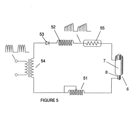](http://stanslegacy.com/uploads/images/gallery/2022-06/WKpYOR7WsjR4QmZF-screenshot-from-2022-06-25-16-06-47.png) | [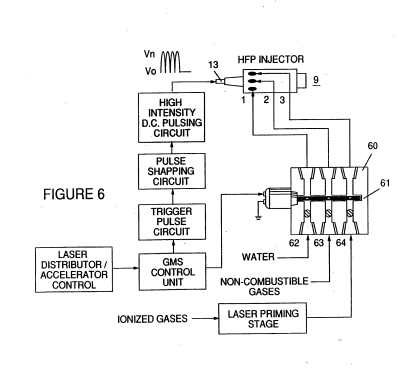](http://stanslegacy.com/uploads/images/gallery/2022-06/HCLF86fMdQMuxbsA-screenshot-from-2022-06-25-16-06-53.png) |
| [](http://stanslegacy.com/uploads/images/gallery/2022-06/jbbljOtNrspzQXLs-screenshot-from-2022-06-25-16-06-31.png) | [](http://stanslegacy.com/uploads/images/gallery/2022-06/HCagrcMh2x9XfZlk-screenshot-from-2022-06-25-16-07-16.png) | [](http://stanslegacy.com/uploads/images/gallery/2022-06/BKlT18F8VbG4FkpB-screenshot-from-2022-06-25-16-07-47.png) |
| [](http://stanslegacy.com/uploads/images/gallery/2022-06/gI1VIukimfS7SEY0-screenshot-from-2022-06-25-16-07-31.png) | [](http://stanslegacy.com/uploads/images/gallery/2022-06/Xobr5XjZEJA3p3K0-screenshot-from-2022-06-25-16-06-42.png) |
Pressure is an **important factor** in the maintenance of the reaction condition and causes the water mist/gas mixture to become intimately mixed, compressed, and destabilized to produce combustion when activated under resonance conditions of ignition.
In accordance with the aforementioned conversion process of my patent and application, when water is subjected to a resonance condition water molecules expand and distend; electrons are ejected from the water molecule and absorbed by ionized gases; and the water molecule, thus destabilized, breaks down into its elemental components of hydrogen (2H) and oxygen (0) in the combustion zone. The hydrogen atoms released from the molecule provide the fuel source in the mixture for combustion with oxygen. The present invention is an application of that process and is outlined in Table I: ##### TABLE I **[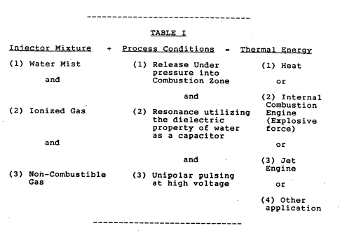](http://stanslegacy.com/uploads/images/gallery/2022-06/sBgjYBvthexRrAii-screenshot-from-2022-06-25-16-16-27.png)****Image Text:** Injector Mixture + Pr ndition = Thermal Energy (1) Water Mist (1) Release Under (1) Heat pressure into and Combustion Zone or and (2) Internal . : Combustion (2) Ionized Gas (2) Resonance utilizing Engine the dielectric (Explosive property of water force) as a capacitor and or and . (3) Jet Engine (3) Non-Combustible (3) Unipolar pulsing . Gas at high voltage or (4) Other application
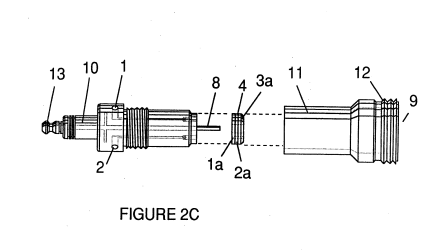
The process occurs as water mist and gases are injected under pressure into, and intimately mixed in the combustion zone and an electrically polarized zone. In the electrically polarized zone, the water mixture is subjected to a unipolar pulsed direct current voltage that is tuned to achieve resonance in accordance with the electrical, mass and other characteristics of the mixture as a dielectric in the environment of the combustion zone. The resonant frequency will vary according to injector configuration and depends upon the physical characteristics, such as mass and volume of water and gases in the zone. As my prior patents and application point out, the resonant condition in the capacitative circuit is determined by the dielectric properties of water: (1) as the dielectric in a capacitor formed by adjacent conductive surfaces and (2) as the water molecule itself is a polar dielectric material. At resonance, current Flow in the resonant electrical circuit will be minimized and voltage will peak. The injector system provides a pressurized fuel mixture for subjection to the resonant environment of the voltage ‘ combustion zone as the mixture is introduced to the zone. In a preferred embodiment, the injector includes concentrically nested serial orifices, one for each of three constituent elements of the fuel mixture. (It may be feasible to combine and process non-combustible and ionized gases in advance of the injector. In this event only two orifices are required, one for the water and the other for the combined gases.) The orifices disperse the water mist and gases under pressure into a conically shaped activation and combustion zone (or locus). Figure 1A shows a transverse cross-section of an injector in which supply lines for water 1 ionized gas 2 and non-combustible gas 3 feed into a distribution disk assembly 4 having concentrically nested orifices. The fuel mixture passes. through a mixing zone 5 and voltage zone 6 created by electrodes or conductive surfaces 7a and 7b (positive) and 8 (negative or ground). Electrical field lines as shown as 6al and 6a2 and 6bl and 6b2. Combustion (i.e., the oxidation of: hydrogen) occurs in the zone 9. Ignition of the hydrogen can be primed by a spark or may occur spontaneously as a result of the exceptionally high volatility of hydrogen. and its presence in a high voltage field. Although a differentiation of the mixing zone, the voltage zone and the combustion zone is made in explaining the invention, that differentiation relates to events or conditions in a process continuum, and ‘as is evident from Figure 1, the zones are not physically discrete. In the zone(s), there is produced an "excited" Mixture of vaporized water mist, ionized gases and other non-combustible gases all of which have been instantaneously released from under high pressure. Simultaneously, the released mixture is exposed to a pulsed voltage in the zone/ locus at a frequency corresponding to electrical resonance. Under these conditions, outer shell electrons of atoms in the water molecule are destabilized and molecular time share is interrupted. Thus, the gas mixture in the injector zone is subjected to physical, electrical and chemical interactive forces which cause a breakdown of the atomic bonding forces of the water molecule. Process parameters are determined based on the size of a particular injector. In an injector sized appropriately for use to provide a fuel mixture to a conventional cylinder in a passenger vehicle automobile engine, the injector may resemble a conventional spark plug. In such an injector, the water orifice is .10 to .15 inch in diameter; the ionized gas orifice is -15 to -20 inch in diameter; and the non-combustible gas orifice is .20 to .25 inch in diameter. In such a configuration, the serial orifices increase in size from the innermost orifice, as appropriate to a concentric configuration. As noted above, the introduction of the fuel components is desirably maintained at a constant rate; maintenance of a back pressure of about 125 pounds per square inch for each of the three fuel gas constituents appears satisfactorily useful for a “spark-plug\* injector. In the Pressurized environment of the injector, spring loaded one-way check valves in each supply line,’ such as 14 and 15, maintain pressure during pulse off times. The voltage zone 6 surrounds the pressurized fuel mixture and. provides an electrically charged environment of pulsed direct current in the range from about 500 to 20,000 and more volts at a frequency tuned into the resonant characteristic of the mixture. This frequency will typically lie within the range of from about 20 KHz to about 50 KHz, dependent, as noted above, on the mass flow of the mixture from the injector and the dielectric property of the mixture. In a, spark-plug sized injector, the voltage zone will typically extend longitudinally about -25 to 1.0 inch to permit sufficient dwell time of the water mist and gas mixture between the conductive sufaces 7 and 8 that form a Capacitor so that resonance occurs at a high voltage pulsed frequency and combustion is triggered. In the zone, an energy wave is formed related to the resonant pulse frequency. The wave continues to pulse through the flame in the combustion zone. The thermal energy produced is released as heat energy. Ina confined zone such as a piston/cylinder engine, gas detonation under resonant conditions produces explosive physical power. In the voltage zone, the time share ratio of the hydrogen and oxygen atoms comprising the individual water molecules in the water mist is upset in accordance with the process explained in my aforementioned patent no. 4,936,961 and application serial no. 07/460,859. To wit, the water molecule which is itself a polar structure, is distended or distorted in shape by being subjected to the polar electric field in the voltage zone. The resonant condition induced in the molecule by the unipolar pulses upsets the molecular bonding of shell electrons such that the water molecule, at resonance, breaks apart into its constituent atoms. In the voltage zone, the water (H20) molecules are excited into an ionized state; and the pre-ionized gas component of the fuel mixture captures the electrons released from the “water molecule. In this manner at the resonant condition, the water molecule is destabilized and the constituent atomic elements of the molecule, 2H and O, are released; and the released hydrogen atoms are available for combustion. The non-combustible gases in the fuel mixture reduce the burn rate of hydrogen to that of a hydrocarbon fuel such as gasoline -or kerosene from its normal burn rate (which is approximately 2.5 times that of gasoline). Hence the presence of non-combustible gases in the fuel mixture moderates energy release and modulate the rate at which the free hydrogen and oxygen molecules combine in the combustion process. The conversion process does not spontaneously occur and the condition in the zone must be carefully fine tuned to achieve an optimum input flow rate for water and the gases corresponding to the maintenance of a resonant condition. The input water mist and gases may likewise be injected into the zone in a physically pulsed \[on/off\] manner corresponding to the resonance achieved. In an internal combustion engine, the resonance of the electrical circuit and the physical pulsing of the input mixture may be required to be related to the combustion cycle of the reciprocating engine. In this regard, one or two conventional spark plugs may require a spark cycle tuned in correspondence to the ‘conversion cycle resonance so that combustion of the mixture will occur. Thus, the input flow, conversion rate and combustion rate are interrelated and optimally should each be tuned in accordance with the circuit resonance at which conversion occurs. The injection system of the present invention is suited to retrofit applications in conventionally fueled gasoline and diesel internal combustion engines and conventionally fueled jet aircraft engines. ##### ##### EXAMPLE 1 Figures 2A, 2B and 2C illustrate a type of injector useful, inter alia as a fuel source for a conventional internal combustion engine. In the cross-section of Figure 2A, reference numerals corresponding to identifying numerals used in Figure 1 show a supply line for water l leading to first distribution disc la and supply line for ionized gas 2, leading to second distribution disc 2a. In the cross section, the supply line for non-combustible gas 3 leading to distribution disc 3a is not illustrated, however, its location as a third line should be self-evident. The three discs comprise distribution disc assembly 4. The supply lines are formed in an electrically insulating body 10 surrounded by electrically conductive sheath/housing 11 having a threaded end segment 12.| [](http://stanslegacy.com/uploads/images/gallery/2022-06/jbbljOtNrspzQXLs-screenshot-from-2022-06-25-16-06-31.png) | [](http://stanslegacy.com/uploads/images/gallery/2022-06/HCagrcMh2x9XfZlk-screenshot-from-2022-06-25-16-07-16.png) | [](http://stanslegacy.com/uploads/images/gallery/2022-06/gWsvHKxaNzmtynhm-image-1656188554549.png) |
Fuel distribution and management systems useful with the injector of this application are described in my co-pending applications for patent, PCT/US90/6513 and PCT/US90/6407
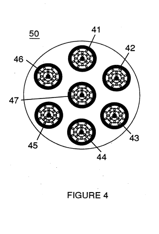
A distribution block for the assembly is shown in Figure 6. In Figure 6 the distribution block pulses and synchronizes the input of the fuel components in sequence with the electrical pulsing circuit. The fuel components are injected into the injector ports in synchronization with the resonant frequency to enhance the energy wave pulse extending from the voltage zone through the flame. In the configuration of Figure 6, the electrical system is interrelated to distribution block 60, gate valve 61 and separate passageways 62, 63, and 64 for fuel components. The distributor produces a trigger pulse which activates a pulse shaping circuit that forms a pulse having a width and amplitude determined by resonance of the mixture and establishes a dwell time for the mixture in the zone to produce combustion. As in my referenced application regarding control and management and distribution systems for a hydrogen containing fuel gas produced from water, the production of hydrogen gas is related to pulse frequency on/off time. In the system shown in Figure 6, the distributor block pulses the fluid media introduced to the injector in relationship to the resonant pulse frequency of the circuit and to the operational on/off gate pulse frequency. In this Manner the rate of water conversion (i.e., the rate of fuel production by the injector) can be regulated and the pattern of resonance in the flame controlled. #### What is claimed is: 1\. The improved method of converting water into a hydrogen containing fuel comprising: > providing a mist of water in a defined zone determined by conductive members, the surfaces: of which define the opposite plates of a capacitive element in a resonant circuit, and > > subjecting the water mist in the zone to a unipolar pulsing electrical signal, such that resonance of the circuit is achieved, whereby hydrogen is disassociated from water molecules in the zone as a gas. 2\. The method of claim 1 in which the resonant circuit is an electrical circuit including an inductive member 3\. The method of Claim 2 in which the inductive member is in series relationship with the capacitive element. 4\. The method of Claim 1 in which non-combustible gases are injected with water into the zone. 5\. The method of Claim 1 in which ionized gases are injected with water into the zone. 6\. The method of Claim 5 in which the ionized gases are subjected to excitation by photons. 7\. The method of Claim 1 or Claim 2 or Claim 3 or Claim 4 or Claim 5 or Claim 6 including the oxidation of the hydrogen gas released to produce thermal energy. 8\. The method of Claim 1 or Claim 2 or Claim 3 or Claim 4 or Claim 5 or Claim 6 including the oxidation of the hydrogen gas released to produce an explosive force of combustion. 9\. The method of Claim 1 or Claim 2 or Claim 3 or Claim 4 or Claim 5 or Claim 6 in which the media in the zone is subjected in the zone to physical pulsing corresponding to the resonance of the circuit. 10\. Apparatus useful in a method for the conversion of water into a hydrogen fuel including: > electrically conductive surfaces that form the opposite surfaces of an electrically capacitive element in a circuit; > > means for injecting water as.a fine mist into the zone defined by the electrically conductive surfaces; and > > means for achieving resonance in the circuit at a frequency determined substantially by the dielectric properties of the water in the zone, whereby hydrogen is disassociated from water molecules in the zone as a gas. 11\. Apparatus in accordance with Claim 10 including means for the injection of gases with water into the zone to produce a mixture and in which the resonant frequency is related to the dielectric properties of the mixture. 12\. Apparatus in accordance with Claim 10 or Claim ll including means for causing ignition of the hydrogen gas. 13\. Apparatus in accordance with Claim 10 or Claim 11 including further means for subjecting the media in the zone to physical pulsing. # CA1234774A1 Hydrogen Generator SystemPDF Download: [SMeyer-CA1234774A1-Hydrogen\_Generator\_System.pdf](http://stanslegacy.com/attachments/45)
> Y e Consumer and Consommation ~ Corporate Affairs Canada et Corporations Canada > (11) (a) wo. 1-234 774 > (45) ISSUED 880405 > (52) CLASS 204-78 C.R. CL. 204-1644 > (51) INT. CL. C25B 1/04aa) cs) CANADIAN PATENT a2 > (54) Hydrogen Generator System > (72) Meyer, Stanley A., | U.S.A. . : > (21). APPLICATION No. 420,908 (22) FILED 830204 mo ! r No. OF CLAIMS 15 | Canad > DISTRISUTED BY THE PATENT OFFICE, OTTAWA. CCA-274 (11-82) #### ABSTRACT > Process and apparatus for dissociating hydrogen atoms from a water molecule by electrical force. Particularly, the separation of the hydrogen and oxygen atoms from the water molecule by the application of a non-regulated, non- filtered, low-power, direct current voltage electrical potential applied to two non-oxidizing similar metal plates having water passing therebetween. The direct current voltage may be continuous, but the action can be enhanced by pulsing the non-regulated and non-filtered direct current voltage. The apparatus comprises various. constructional configurations and alternative embodiments for segregating the generated hydrogen gas from the oxygen gas. The water need not be pure and may contain contaminants. The release of the hydrogen and oxygen atoms causes the contaminants to fall away, thereby enabling the system to be utilized in a liquid slurry removal system. Alternatively, the recombining of the hydrogen and oxygen would give pure water. ##### Background 1234774 The potential availability of hydrogen as a Supplement to and eventually complete replacement of the present day available fuels is most appreciated. The efficiency of hydrogen as a fuel and its pollution free qualities further enhances its attractiveness. The prior art systems have been Successful in splitting the Sos. . hydrogen atoms from the oxygen. However, cost per Btu is most prohibitive and completely restricts the known process from commercialization. The most commonly understood method of separating the hydrogen and oxygen atoms from water is electrolysis. This comprises placing a direct current voltage to.a solution of water and potassium hydroxide. When current flows, an exchange of ions and electrons occurs between the electrodes. Hydrogen atoms collect at the negative electrode (cathode) and oxygen atoms at the positive electrode (anode). A Separation between electrodes separates the gases. Significantly, this process requires a chemical solution; that is, it does not Operate when using pure water. Furthermore, the cast per million Btu is in the order of three times the cost of gasoline. Other electrolysis processes have been devised and disclosed but are more sophisticated, complicated, complex and costly with attendant unreliability. Another Process under Study. comprises nuclear energy to supply heat in a thermal of the hydrogen dissociation. The problems with the process include the lack of container materials that can withstand temperatures involved (900°C) and a practical method of attaining such temperatures. The addition of inorganic compounds to the water permits lower temperatures but again, adds to the complexity of the process & commercial method known as the Bosch process, consists in passing steam over highly heated carbon in the presence of a Suitable catalyst. Carbon monoxide, CO, and hydrogen are first formed as shown in the following equation:[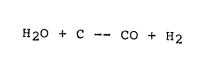](http://stanslegacy.com/uploads/images/gallery/2022-06/GQhuj3coI20Sjhio-screenshot-from-2022-06-25-00-42-40.png) The resulting carbon monoxide then reacts with more steam, forming carbon dioxide and hydrogen: [](http://stanslegacy.com/uploads/images/gallery/2022-06/mYfFd4UZ6G4g8HIw-screenshot-from-2022-06-25-00-42-06.png) The carbon dioxide is Separated from the hydrogen by passing the mixture through water under pressure; the carbon dioxide dissolves in the water and leaves the hydrogen pure or nearly so. Another process consists in the action of steam on methane, CH4. The equations for the reactions that take place are: [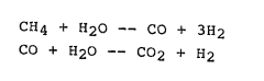](http://stanslegacy.com/uploads/images/gallery/2022-06/7wpNBS3fsBfax18b-screenshot-from-2022-06-25-00-42-10.png) The resulting carbon dioxide and hydrogen are separated as in Bosch process. In a similar way, hydrogen may be obtainéd ‘from other hydrocarbons. Hydrogen is also obtained as a by-product from processes designed to prepare other substances, for example in the preparation of chlorine by electrolysis of sodium chloride solution: [](http://stanslegacy.com/uploads/images/gallery/2022-06/Dkjnw1Djl1EKYkFL-screenshot-from-2022-06-25-00-44-00.png) and other important processes. The symbol **(aq)** tells us that the substances are present in water (aqueous) solutions. Finally, there is the natural way of attaining hydrogen by photosynthesis. At best the process is still in the laboratory small-scale stage and those in the art acknowledge the process can produce hydrogen with an efficiency of only 373%. It is generally acknowledged by scientists that every form of hydrogen production must be explored ~~ even 1£ it is too costly, inefficient, or impractical. But, more significantly, hydrogen will be the fuel of the future. The only question remains how and when it will be produced.Reference is made to the publication Cheaper Hydrogen. Popular Science, September 1981, pages 10 through 14, that reviews and updates the above-noted processes.
##### Summary of Invention The process of the present invention, unlike those of the prior art, is a simple, efficient, and low cost process for separating the hydrogen and oxygen atoms from water. No chemicals are added to the water and the electrical power utilized is only negligible. In its most fundamental concept the water (which may be uncontaminated or pure water, salt water, or contaminated water) is passed between two plates of similar non-oxidizing metal. The one plate has placed thereon a positive potential and the other a negative potential from a very low direct current voltage power source. The hydrogen atoms are separated and collected for utilization. The contaminants in the water are dissociated and the dissociated parts may be collected and disposed of or utilized. This in turn leads to recombining the hydrogen’ and oxygen to form pure water. The direct current voltage is non-regulated and non-filtered. Experimentation demonstrated that the direct current voltage acts as a **static force** on the water molecules; whereas the rippling direct current voltage acts as a **dynamic force**. Pulsating the direct current further results in a dynamic force and enhances considerably the splitting of the atoms from the water molecules, The apparatus for carrying out the process is extremely simple and can be manufactured most inexpensively. Certain plate arrangements and configurations are disclosed with graphical illustration of relative efficiency. Alternative structure for separating and collecting the hydrogen from the oxygen is disclosed. ##### Objects It is accordingly a principal object of the present invention to provide method and means that is operable for producing hydrogen and oxygen from any natural water irrespective of its purity. Another object of the present invention is to provide a hydrogen/oxygen generator that is operable from very low electrical power, extremely efficient, and wherein the cost o£ Operation is minimal. Another object of the present invention is to provide a. hydrogen/oxygen generator using water containing contaminants, and thereafter recombining the hydrogen/oxygen to form pure water. Still another object of the present invention is to provide a hydrogen/oxygen generator that utilizes apparatus of simple and low cost materials, and which structure can be made in varying sizes, and duplicated without loss of efficiency. Other objects and features of the present invention will become apparent from a reading of the detailed description of the preferred embodiment and its alternative structures when taken in conjunction with the drawings in which: ##### ##### BRIEF DESCRIPTION OF THE DRAWINGS Figure 1 is an illustration in cross~section of the operable constructed preferred embodiment of the present invention; [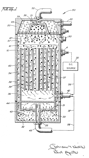](http://stanslegacy.com/uploads/images/gallery/2022-06/mLY7btVVcR3JjsJl-screenshot-from-2022-06-25-00-53-18.png) Figure 2 illustrates a coaxial cluster or array of plates utilized in the embodiment of Figure 1; [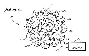](http://stanslegacy.com/uploads/images/gallery/2022-06/Ao9KqTXZ4nFHWdrQ-screenshot-from-2022-06-25-00-53-54.png) Figure 3 is a first alternative plate arrangement, a concentric coaxial array; [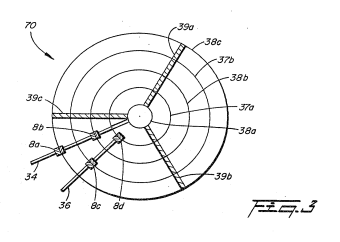](http://stanslegacy.com/uploads/images/gallery/2022-06/Hikgx27AT0VxhMBi-screenshot-from-2022-06-25-00-53-58.png) Figure 4 is another alternative plate arrangement, a flat plate array; [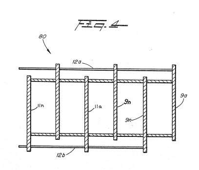](http://stanslegacy.com/uploads/images/gallery/2022-06/tgjspqmga2Y3Ha4F-screenshot-from-2022-06-25-00-54-02.png) Figure 5 diagrammatically illustrates applying a voltage potential to several plates; [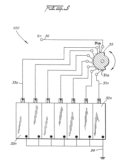](http://stanslegacy.com/uploads/images/gallery/2022-06/HRdSvzDPjPtwTepe-screenshot-from-2022-06-25-00-54-07.png) Figure 6 illustrates the principles of the present invention in its most simplified embodiment; [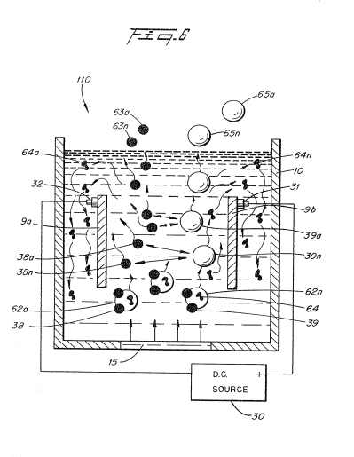](http://stanslegacy.com/uploads/images/gallery/2022-06/CnziGnXLMZgEgWZx-screenshot-from-2022-06-25-00-54-13.png) ‘Figure 7 is the preferred embodiment shown in Figure 1 except in this illustration, the view is perspective; [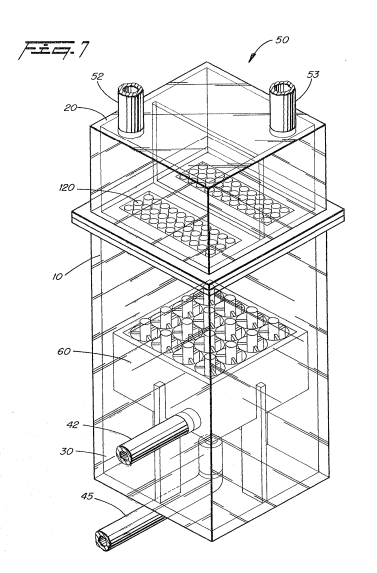](http://stanslegacy.com/uploads/images/gallery/2022-06/ryrIK0x7Npz5Fqqo-screenshot-from-2022-06-25-00-54-31.png) Figure 8 is a graphical illustration of amperage versus gas generated, and effect as to condition of water; [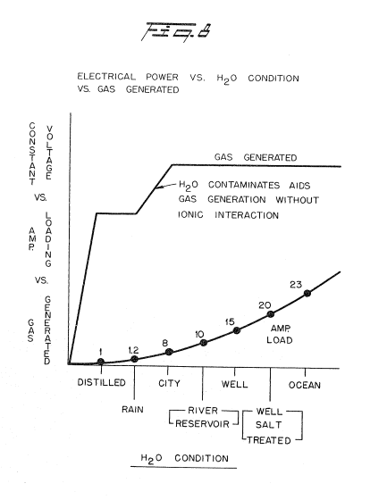](http://stanslegacy.com/uploads/images/gallery/2022-06/Lk7cApsW2y4i6AgT-screenshot-from-2022-06-25-00-54-36.png) Figure 9 is a graphical illustration of D.c. voltage versus gas generated, and increases in water temperatures; . . generation [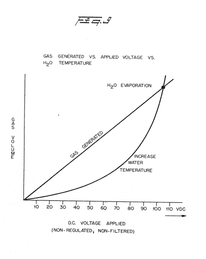](http://stanslegacy.com/uploads/images/gallery/2022-06/L7XaE0tvcPTZjrp4-screenshot-from-2022-06-25-00-54-41.png) Figure 10 is a graphical illustration of. gas generator versus tube length in a tubular plate arrangement; [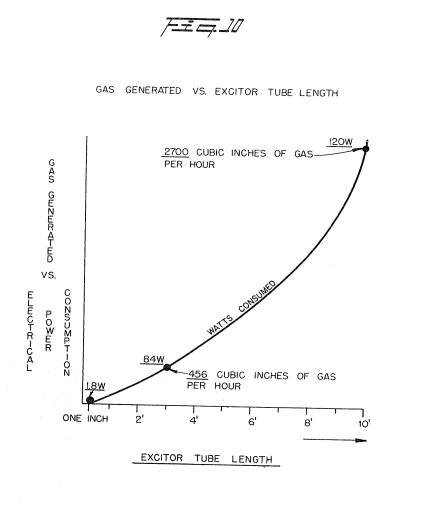](http://stanslegacy.com/uploads/images/gallery/2022-06/1xG7aikX6KQObmo0-screenshot-from-2022-06-25-00-54-46.png) ‘Figure 11 is a graphical illustration of applied power versus gas generated for pure water; [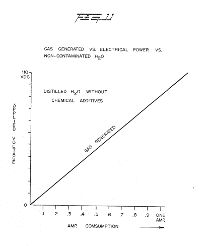](http://stanslegacy.com/uploads/images/gallery/2022-06/YwmAtZDvqD6Gh1Um-screenshot-from-2022-06-25-00-54-51.png) Figure 12 is a graphical illustration of gas generation for three different geometrical configurations of plate structure; [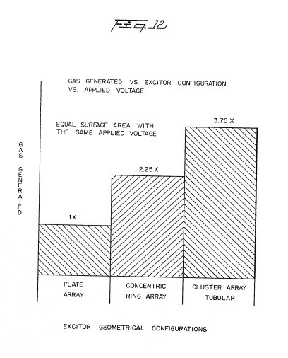](http://stanslegacy.com/uploads/images/gallery/2022-06/HGEtvCPGwelpMEG1-screenshot-from-2022-06-25-00-54-56.png) Figure 13 is a graphical illustration of gas generated with the plates having increasing separation; [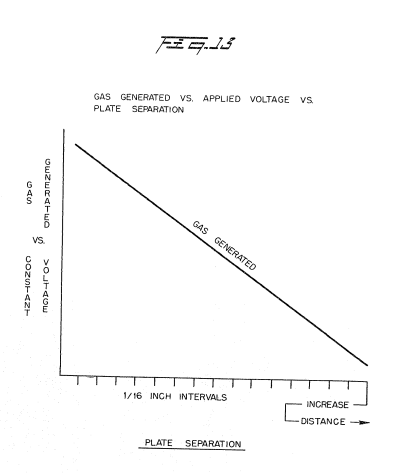](http://stanslegacy.com/uploads/images/gallery/2022-06/pmDgFARiIdQmOx19-screenshot-from-2022-06-25-00-55-01.png) Figure 14 is a graphical illustration of electrical costs versus gas generated, and increases in Exciter Plate 5; [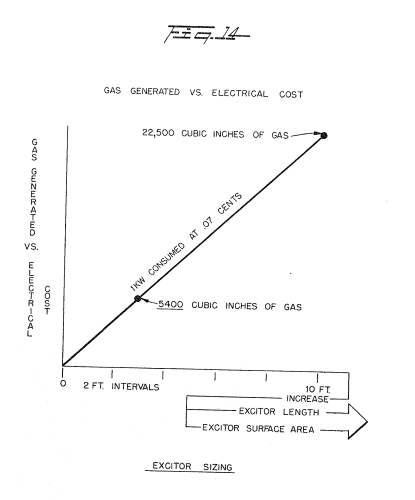](http://stanslegacy.com/uploads/images/gallery/2022-06/a3P8CZIuZL1OSFP8-screenshot-from-2022-06-25-00-55-05.png) Figure 15 is a graphical illustration of different applied power versus gas generated, for various types of water conditions; and [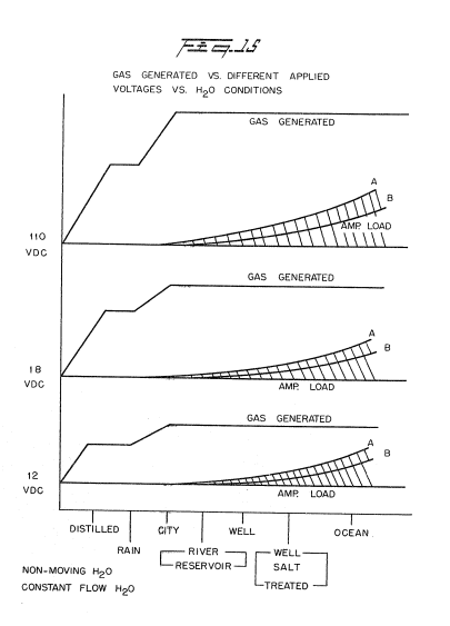](http://stanslegacy.com/uploads/images/gallery/2022-06/vAjB6EBMs6ohlJ0u-screenshot-from-2022-06-25-00-55-10.png) Figure 16 is a graphical illustration of gas generated versus pulse direct current repetition rate. [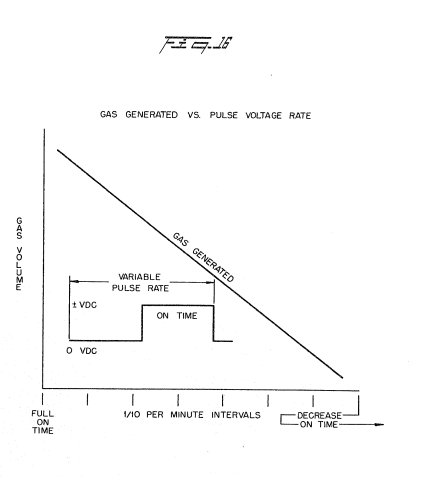](http://stanslegacy.com/uploads/images/gallery/2022-06/KJKMNjZy6frKoyAV-screenshot-from-2022-06-25-00-55-16.png) ##### ##### Detailed Description of Invention as Depicted in Drawings With particular reference now to Figure 6, there is illustrated schematically in cross-section the invention in its most simplified embodiment. A structure 110 contains water supply 15 comprising molecules 62a xxx 62n, of hydrogen 38a xxx 38n, oxygen, 39a xxx 39n, and foreign substances 64a xxx 64n. A pair of plates 9a and 9b consisting of non-oxidizing metal ~- and both of the same metal, are submerged in the water 15. Attached to terminal 32 on the first of the plates 9a is a wire having its other end connected to the negative terminal power source 30 and another wire is connected to terminal 31 on Plate 9b the other end of such wire being connected to the positive terminal of the aforesaid direct current voltage electrical source 30, The direct current voltage applied to the water passing between plates 9a and 9b is sufficient to dissociate the hydrogen atoms 38a xxx 38n and oxygen atoms 39a xxx 39n (appearing as bubbles) from the water molecules 62a xxx 62n. The forceful action of the applied potential attacks the Molecule structure of the water and not its atomic structure. The foreign substance or contaminants 64a xxx 64n are broken” away from the water molecule 62a xxx 62n, and spill over the outside area of the plates 9a and 9b to a collector at the bottom of the tank 10. The hydrogen gas 63a xxx 63n and oxygen gas 65a xxx 65n rises above the liguid. The gases are separated, collected and thereafter utilized all as set forth below. The process shown with the apparatus of Figure 6 is operable, as depicted schematically, in its most crude form. To increase and enhance the action, the process and the apparatus are improved upon as shown in the constructed and preferred embodiment of Figure 1 (a cross~sectional view) and Figure 7 (a perspective view). The voltage source 30 (shown schematically in Figure 5) supplies a direct current voltage that is rectified but not filtered and not regulated. That is, the direct current voltage is rippled and unregulated. The varying amplitude $S3K5, ripples, in terms of applied force act as a constant static physical force. The amount of electrical power required by the hydrogen/oxygen generator of the preferred embodiment, as illustrated, is surprisingly minimal. For the embodiment shown in Figures 1, 2 and 7, the power source 30 supplies 12 volts at J ampere. It can be appreciated, that increasing the voltage would enhance the forceful action upon the water molecule. The correlation of gas generated vs, electrical energy is graphically illustrated in Figure 11. The gas generated is a linear function of the magnitude of voltage applied. However, there is a serious limitation to increasing the voltage. As the voltage/current is increased the temperature of the water increases and eventually reaches a condition where steam is generated -- as illustrated graphically in Figure 9. Further, as shown graphically in Figure 8, the current versus gas , generated is also a function of the type of water utilized. Therefore, in lieu of increasing the electrical power to enhance the action on the water molecules, other conditions must be considered. The first is to alter the plate source direct current voltage waveform, With particular reference to Figure 5 there is illustrated an electronic switch for switching on and off the rippled D.C. output of supply 30. The- ripple is not removed. The plates 32a XXX. 32n are connected to a common ground 34. The positive terminals 33a xxx 33n are connected respectively to contacts 31a Xxx 31n of switch 35 rotatively making and breaking contact with the direct-current voltage source 30. In function the pulsed rippled output voltage functions to forcefully apply to the water molecules a dynamic force, the pulse repetition rate determining the amount of gas generated. Other structured factors affecting the hydrogen gas generation comprise altering (1) plate size, (2) plate spacing, (3) number of plates, and (4) the plate configuration. All of these factors have been taken into consideration in the development of a plate configuration to provide optimum results for a preferred embodiment. With reference to Figure 2, there is shown an array or cluster of tubular plates utilized in the preferred embodiment of Figures 1 and 7. The term "plate" hereinafter, is intended to convey a large area electrical surface; and whether the surface is flat, curved, tubular or otherwise, is of no consequence except as hereinafter defined. Particularly, each tubular plate comprises an outside tube 32a XXX 32n, and an inside tube 33a xxx 33n. Connecting each of the inner tubes 33a xxx 33n is a terminal wire 34; and connecting each of the outside tubes through a common ground is a terminal wire 36. The two terminal wires 34 and 36 are connected to the positive and negative side respectively of the direct current voltage source 30. Intermediate the outside and inside tubes are a series of spacers 35a Xxx 35n.. The coaxial tubes in an array are shown pictorially in the perspective view of Figure.7. With particular reference to Figure 3 there is illustrated, as an alternative to that utilized in the preferred.embodiment, another plate arrangement and configuration... This concentric ring array comprises a series of co-axial radially spaced tubes with equal spacing between adjacent tubes. The center tube 38a and the alternate tubes 38b.and 38c serve as the positive plates connected to positive wire terminal 34. Each of the tubular plates 38a, 38b, and 38c is interconnected via connectors 8a and 8b to wire terminal 34. The three spacers 39a, 39b, and 39c maintain a uniform spacing between the respective tubular plates. With particular reference to Figure 4 there is shown still another plate arrangement and configuration. In this embodiment, shown in cross-section, the positive plates 9a xxx 9n are interconnected by electrode 12a whereas the negative plates lla xxx lin are interconnected by the electrode 12b. With particular reference to Figure 12 there is illustrated graphically the efficiency of the tubular plate array of Figure 2, the cluster tubular array of Figure 3, and the flat plate array of Figure 4. Specifically there is shown the gas generation versus the plate configuration. It can be appreciated from this graph why the embodiment of Figure 1 includes the cluster tubular array of Figure 2. As stated above another factor affecting the gas generation output is the plate separation. With particular reference to Figure 13 there is illustrated graphically plate Spacing versus gas generation. As can be seen, the greater the spacing the less gas generation. The efficiency versus spacing of the plates is a linear decrease with spacing. As stated above, the applied direct current voltage across the positive current voltage plates having water therebetween is a force applied -- in the nature of a physical force -- to the water molecules. The applied force is sufficient to cause the hydrogen and oxygen atoms to dissociate themselves from the Water molecule and anything else that may be included therewith. In the aforementioned prior art system of hydrogen gas generation such as the electrolysis process, it is essential that the water be distilled or otherwise made pure. To determine the relative differences of the amount of gas generated versus the purity of the water, analysis was made of distilled water, rain water, city tap water, river water, well water untreated, well. water treated, and sea water. The results of gas generation versus electrical power are illustrated in Figures 8 and 15 graphically for each of the waters tested. It appears that water containing contaminants aids gas generation; however, the nature of the water contaminants appears to have no significance. The hydrogen atoms and oxygen atoms dissociate themselves from the water molecule. Anything else that may be included in the water is also bombarded loose and overflows the tank 37 and falls to the bottom 43. Having now examined the applied electrical force phenomena the physical configuration of the electrical plates, the power applied, and the condition of the water, reference is made specifically to-the construction, function and operation of the hydrogen gas generator of the present invention which is shown in cross-section in Figure 1 and in perspective in Figure 7. The container 10 is a square elongated box configuration completely enclosing and sealing the components as hereinafter described. Water, from which the hydrogen gas is to be taken, enters via inlet 42 to the chamber 36. The water is pumped or enters under normal pressure from a source via line 56. As mentioned above, the water need not be pure and hence may originate from any source. The water from source 42 enters chamber 36 which is a free area to an open top enclosure 37. The water entering chamber 36 is caused to rise upwardly through the plates of the cluster 60 previously described in more detail relative to Figure 2. Applied to the inner tubular structures is a positive direct current voltage, and to the outer tubular structures of the cluster array 60 is applied a negative direct current voltage. The direct current voltage is applied via terminals 4 connected to a suitable direct current voltage power source 30. The hydrogen gas is depicted in Figure 1 as a solid circle 38 whereas the oxygen gas is depicted as the open circles 39. OSes The separated hydrogen and oxygen“gas rise into the accumulator chamber 47, Not all of the water molecules are broken up into their various atomic components. Thus, the unspent water 41 spills over the top of chamber 37 and drops down through outer chamber 54 and back to reservoir 43. As aforesaid, it is not necessary to utilize pure (uncontaminated) water, the intake water will include several forms of contaminants. As best understood, when the water molecule is bombarded with the dynamic and static electrical force, the contaminants adhering to the water molecules are shaken loose and released therefrom. The contaminants, too, rise to the top of chamber 37 and fill a part of the spillway 41. in that the contaminants do not contain hydrogen or oxygen, there will be no atomic breakup. The combination of water with contaminants drops down into extraction chamber 43. In the extraction chamber 43 most of the sediment or sludge will drop to the bottom of. the chamber 32. The water with most of the sediment removed passes through the ports 33a xxx 33n, through charcoal filter 31, and into return water chamber 44, The uppermost portion of the water in chamber 44 drops into Standpipe. 35. The water cleansed of substantially all contaminants, exits via pipe 45 and then through line 55 and back to inlet pipe 42. The combined water from inlets 55 and 56 is again processed as aforesaid. ##### THE EMBODIMENTS OF THE INVENTION IN WHICH AN EXCLUSIVE PROPERTY OR PRIVILEGE IS CLAIMED ARE DEFINED AS FOLLOWS : 1\. A system for the release of hydrogen and oxygen gas from natural water having no electrolyte added thereto, comprising: > a housing of non-corrosive, non-reactive, and non-oxidizing material, > > simi laa a pair of’electrical voltage conductive plates sSimitarly of . NON Gorrodeble : : : : a non-reactive, 1 and non-oxidizing material positioned in said housing with a spatial relationship to one another, > > means for passing said natural water between said plates; and > > means connecting one of said plates to a negative output terminal and the other of said plates to a positive output terminal of a variable D.c. voltage source which includes circuit means for restricting the current thereof to a negligible value relative to the magnitude of the voltage, Said voltage forming a positive electrical voltage zone adjacent said plate having said positive terminal connected thereto and a negative voltage zone adjacent said plate having said negative output terminal connected thereto, > > voltage when applied to said plates having a sufficient magnitude to cause the hydrogen atoms of the water molecule to be attracted to said negative zone, and the oxygen atoms to be attracted to said positive zone, > > and thereby force the hydrogen atoms and the oxygen atoms to disassociate themselves from the water molecule at a rate in dependence on the magnitude of the voltage applied to said plates. 4234774 2\. The system as set forth in claim 1 including means selectively to vary the voltage and maintain it at a constant level. 3\. The system as set forth in claim 1 wherein said variable voltage source further comprises pulsing circuit means and wherein the rate of release of said hydrogen and oxygen gas is directly related to the repetition rate of the voltage output pulses of said pulsing circuit. 4\. The system as set forth in claim 3 wherein the magnitude of the output voltage of said variable voltage source is interrelated to the pulse repetition rate of the output pulse of sand pulsing circuit, and wherein the rate of the hydrogen and oxygen atoms disassociating from the water molecule is related to the magnitude of said voltage and the pulse repetition rate of said pulses. 5\. The system as set forth in claim 1 wherein said variable voltage source includes means for varying the magnitude of said voltage from 0 volts to in excess of 110 volts and for restricting the current thereof to less than 1 ampere. 6\. The system as set forth in claim 1, characterized in that said non-oxidizing plates are coaxial or alternatively have concentric surfaces. 7\. The system as set forth in claim 1, characterized in that said non-oxidizing plates are a plurality of plates in an array. 8\. The system as set forth in claim 1, characterized in that said non-oxidizing plates are a cluster of coaxial plates in an array. 9\. The system as set forth in claim 1, characterized in that said non-oxidizing housing further comprises a gas collection chamber for maintaining a preset volume of gas under pressure. 10, The system as set forth in claim 7, characterized by switching means interconnected to each of said plates in said array and to said voltage source for switching in and out selected ones of said array of plates from said voltage source. 11\. The system as set forth in the spacing between the plates, surface area of the plates, the configuration of the plates and plates is adapted to be changed claim 1 wherein at least one of the length of the plates, the the the voltage applied to the so as to alter the production number of plates, rate of hydrogen and oxygen gas. 12\. The system as set forth in claim 1 further comprising means to separate the produced hydrogen and oxygen gases. 13\. The process of releasing hydrogen and oxygen gas from natural water having no electrolyte added thereto, comprising: > passing said natural water through a contained area having nen-daorrodable AGR-EOEEOSLVG, non-reactive electrically conductive plates therein, > > a pair of similar non-oxidizing, ’ applying a variable D.C. positive voltage across one of > > said plates and applying a variable D.C. negative voltage across the other of said plates, restricting the current of said variable voltages applied rash to said plates to a negligible value 4p GOS. to said voltage, > > said positive voltage forming a positive voltage zone adjacent said plate having a positive voltage applied thereto and said negative voltage forming a negative voltage zone adjacent the plate having a negative voltage applied thereto, > > Said variable voltages applied to said plates being of sufficent magnitude to cause the positive atoms of the water molecule to be attracted to the negative voltage zone and said plate and the negative atoms of the water molecule to be attracted to the positive voltage zone on said other plate, > > thereby forcing the hydrogen atoms and the oxygen atoms to disassociate themselves from the water molecules at a rate dependent on the magnitude of said variable voltage, > > and varying the magnitude of the variable voltage applied to said plates to vary the rate at which the hydrogen atoms and the oxygen atoms disassociate themselves from the water molecule. 14, The process of claim 13 further comprises pulsing the variable voltage applied to said plates at a variable repetition rate and varying the physical parameters of said plates in an interrelationship with said variable voltages. 15\. The system as set forth in claim 7 further comprising switching means interconnected to each of said plates in said array and to said voltage source for switching in and out selected ones of said array of plates from said voltage source and wherein the number of said plates having said voltage source switched therein is directly related to the rate of hydrogen atoms and oxygen atoms disassociating from said water molecule # CA1234773A1 Resonant Cavity Hydrogen Generator That Operates with a Pulsed Voltage Electrical PotentialPDF Download: [SMeyer-CA1234773A1-Resonant\_Cavity\_Hydrogen\_Generator\_That\_Operates\_with\_a\_Pulsed\_Voltage\_Electrical\_Potential.pdf](http://stanslegacy.com/attachments/46)
Consumer and Consommation Corporate Affairs Canada al Corporations Canada > (11) (A) No. 1 234 773 > (45) ISSUED 880405 > (52) CLASS 204-78 C.R. CL. 158-14 > (51) INT. CL. ¢C25B 1/04) > (54) Resonant Cavity Hydrogen Generator That Operates With a Pulsed Voltage Electrical Potential > (72) Meyer, Stanley A., U.S.A. > (21) APPLICATION No. 420 ,902 > (22) FILED 830204 > (30) PRIORITY DATE U.S.A. (P65,797) 820924 No. OF CLAIMS 22 > > DISTRIBUTED BY THE PATENT OFFICE, OTTAWA. CCA-274 (11-82) #### ABSTRACT A process is disclosed for producing hydrogen and oxygen gasses from water which includes having water in a cavity which has a selected resonant frequency and applying of voltage potential to exciter elements in contact with the in the cavity so that one element maintains a positive charge and the other a negative charge. The voltage potential is pulsed at a frequency matching the resonant frequency of the cavity. The apparatus includes preferably a spherical shell which is a first exciter element formed of an electrically conductive non-reactive material and defines the boundary of a cavity. The cavity has a pre-determined resonant frequency and a second exciter element of the same material as the the first element is located within the cavity in selected spaced relationship therewith. Water can flow into the cavity gasses produced outflow from the top of the cavity, such gasses being obtained from the water in the cavity when an electrical pulsating potential is applied to the exciter elements ##### ##### RESONANT CAVITY FOR A HYDROGEN GENERATOR CROSS REFERENCE: In the non-electrolysis process disclosed and Claimed in my co-pending Canadain patent application, Serial Number 420,908, filed 4 February 1983, for HYDROGEN GENERATOR SYSTEM, for separating hydrogen and oxygen atoms from water, water is passed between two plates of similar non-oxidizing metal. The one plate has placed thereon a positive potential and the other a negative potential from a very low-direct— current power source. The action of the direct current voltage causes the hydrogen and oxygen atoms to be separated. The contaminants in the water also separated out and may be collected or utilized and disposed of. This in turn lends the process to recombining the hydrogen and oxygen into pure water. The direct current voltage applied to the plates is non-regulated and non-filtered. The direct current acts as a static force on the water molecules whereas the rippling direct current voltage acts as a dynamic force. Pulsating the direct current further acts as a dynamic force and enhances considerably the splitting of the atoms from the water molecules. An increase in voltage potential further increases the hydrogen output. Certain plate arrangements and configurations with graphical illustrations of relative efficiency are disclosed. In my co-pending patent application, supra, it was shown that the hydrogen gas generator is variably increased by varying the construction of the exciters; more particularly, by (1) increasing the area of the plates, (2) reducing the Space between the plates, and (3) altering the physical configuration of the plate. ##### SUMMARY OF THE INVENTION: The basic structure of and principles of operation disclosed in the aforesaid co-pending patent application are utilized. The non-oxidizing exciters are of a construction, spherical in a preferred embodiment, with a given spacing between the positive and negative elements to form a resonant cavity at a given frequency. The direct current voltage is pulsed at a repetition rate (frequency) to match the resonant wavelength. At the matched frequency the action cof the 5 pulsed direct current voltage is enhanced considerably. The forceful action on the water molecule causes the molecules to break into their atomic structure at a much more rapid rate; thereafter, the gas atoms are set into motion within the resonant cavity, thereby increasing velocity to a jet-like action as they are released from a port. The single resonant cavity has a controlled size port for the utilization of the high velocity gasses. The resonant cavity plate structure in a preferred arrangement is an array of elements. The gasses emitted from the array are combined and expelled as high velocity gasses from a common nozzle and utilized. A principal object of the present invention is to provide an improved method and apparatus for the separation of hydrogen/oxygen gasses from water. In accordance with one aspect of the present invention there is provided a process for producing a gaseous medium which includes hydrogen and oxygen from water, comprising: providing at least one pair of spaced apart electrically conductive , non-oxidizing exciter elements in association with a cavity having a selected resonant frequency and in which there is water, said exciter elements being in 4 contact with the water in the cavity, applying a voltage potential to said exciter elements such that one element maintains a positive charge and the other a negative charge, 30. and pulsing the voltage patential at a frequency matching the resonant. frequency of the cavity. In accordance with a further aspect of the present invention there is provided apparatus for producing a gaseous, medium which includes hydrogen and oxygen from water 35 comprising a first exciter element formed of an electrically conductive non-reactive material having a surface which defines the boundaries of a cavity, said cavity having a predetermined resonant frequency with a quantity of water therein, a second exciter element of the said same material within said cavity in selected spaced relationship from said first exciter element, means permitting the inflow of water into said cavity and means permitting the outflow of gasses from said cavity, said gasses being obtained from water in the cavity when an electrical pulsating potential is applied to said exciter elements. ##### ##### BRIEF DESCRIPTION OF DRAWINGS: Figure 1 is a schematic illustration of the structure of the present invention in its most simplified arrangement. [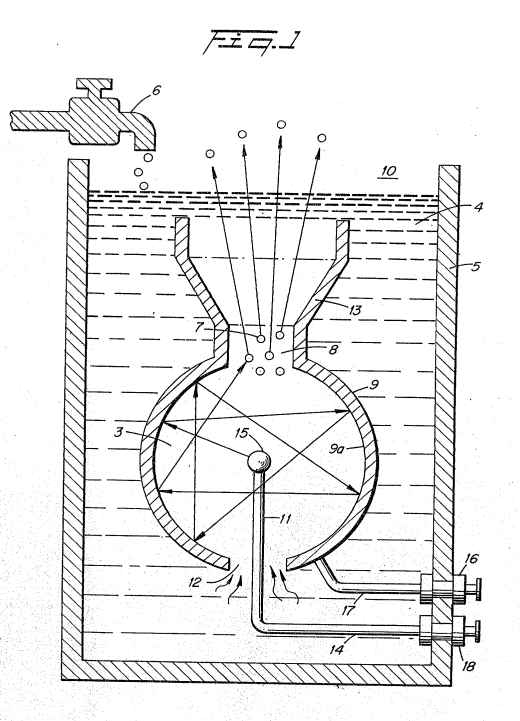](http://stanslegacy.com/uploads/images/gallery/2022-06/bByhlxezsgl28oj2-screenshot-from-2022-06-25-01-03-24.png) Figures 2, 2A, and 2B, are a series of waveforms illustrating the pulse rate of the direct current to’ match the resonant frequency of the structure of Figure 1.| [](http://stanslegacy.com/uploads/images/gallery/2022-06/xcHYGJAnsirvowzJ-screenshot-from-2022-06-25-01-03-30.png) | [](http://stanslegacy.com/uploads/images/gallery/2022-06/tnWkcNIAjufxQnAA-screenshot-from-2022-06-25-01-03-35.png) | [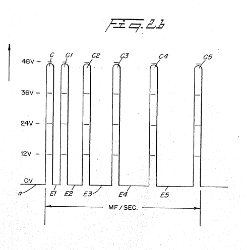](http://stanslegacy.com/uploads/images/gallery/2022-06/Qt1LQ5CYMf7cyiyV-screenshot-from-2022-06-25-01-03-40.png) |
| [](http://stanslegacy.com/uploads/images/gallery/2022-06/lZ6f43kmSzeePYUU-screenshot-from-2022-06-25-01-04-17.png) | [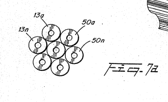](http://stanslegacy.com/uploads/images/gallery/2022-06/zXhKLjHmxVKzDSFP-screenshot-from-2022-06-25-01-04-12.png) |
It has been found that the distance between plates of the exciters will have, or can be adjusted to have, **a ‘wavelength or partial wavelength, or a multiple wavelength**, related to the motion of the **water molecule** in **travelling from the one plate to the other**. Therefore, the structure is constructed to be a resonant cavity at some given frequency of the molecular motion.
[](http://stanslegacy.com/uploads/images/gallery/2022-06/bByhlxezsgl28oj2-screenshot-from-2022-06-25-01-03-24.png)With specific reference again to Figure 1, the distance from the outer surface of the central element 15 to the inner surface 9a of the outer spherical element 9 will be at some wavelength correlated to the molecular motion of travel. When the wavelength is matched with a physical force equal in frequency to that wavelength the inner area becomes a resonant cavity. As understood in resonant cavities of an electron nature, the molecules are set into motion and will be bombarded back and forth from the one surface to the next continuously so long as the initial force is applied. In the sphere of Figure 1, the directions that the water molecules may travel from the inner sphere 15 to the surface 9a of the other sphere 9 is of an infinite number. Considering a single molecule, the water molecule's motion will under normal conditions be impeded by the water. If the distance between the inner and outer sphere is co-related to a wavelength related to the frequency of the pulsating direct current applied to the water, the water molecule will be set in motion and thereafter enhanced in motion in the resonant cavity 3 and overcome the impediment of water. Further, the molecule upon striking the inside surface of the outer sphere, will be reflected and directed to an angular surface where it again will be reflected. This action continues indefinitely and will continue until the applied energy is terminated. Thus, a resonant cavity causes the water molecule to travel back and forth continuously and at a velocity that increases geometrically.The above-noted single molecule's motion of travel will be further increased in velocity when it is considered that the **number of water molecules is infinite** and the striking force is not only from **surface-to-surface** but also from **molecule-to-molecule**.
The enhanced physical action on the water molecule in the resonant cavity 3 will directly affect the breaking up of the molecule into its gaseous atomic structure. As this occurs, the hydrogen, oxygen and other gasses that may be released from the water will be similarly set into motion. The gas atoms will be reflected from the surface 9a and bombard each other in geometric proportion to the energy applied. The water impediment now is relatively insignificant. [](http://stanslegacy.com/uploads/images/gallery/2022-06/tnWkcNIAjufxQnAA-screenshot-from-2022-06-25-01-03-35.png)With reference to the graph of Figure 2, the direct current input voltage a is pulsed at a repetition rate, as shown by waveform 6, (per second) **equal to the resonance frequency of the cavity 3**. To enhance the forceful action of the applied pulsed direct current voltage/potential on the water molecule and the sub-atomic action for the release of gasses, the pulsing of the direct current is periodically interrupted as shown in the graph of Figure 2A. That is, the pulse frequency and pulsed direct current C, C1, and C2 is interrupted in uniform intervals d1, d2, and d3.[](http://stanslegacy.com/uploads/images/gallery/2022-06/Qt1LQ5CYMf7cyiyV-screenshot-from-2022-06-25-01-03-40.png)Again, the pulsed direct current may be **periodically interrupted**, That is, the interruption between pulses C, C1, C2, and C3... is for different time periods: e, e1, e2, and e3.
Returning to Figure 1, an opening @ is provided in the uppermost portion of the outer sphere 9 of the resonant cavity 3 structure. The travel of the gas atoms 7 **bombarding back and forth in the resonant cavity** 3 will eventually pass through the opening 8. However, the movement of the gas atoms 7 has been accelerated as aforesaid and when they pass through the opening 8 they are at an extremely high velocity. That is, the motion of the gas atoms 7 will pass out of opening 8 as though they are jet propelled. The structure of Figure 1 is that of a sphere 9 with another sphere 15 positioned therein. The spacing between the outer surface of the inner sphere 15 to the inner wall 9a of sphere 9 provides a resonant cavity to a given frequency of the physical force of the direct current voltage. Other resonant cavities may be utilized in other arrangements. [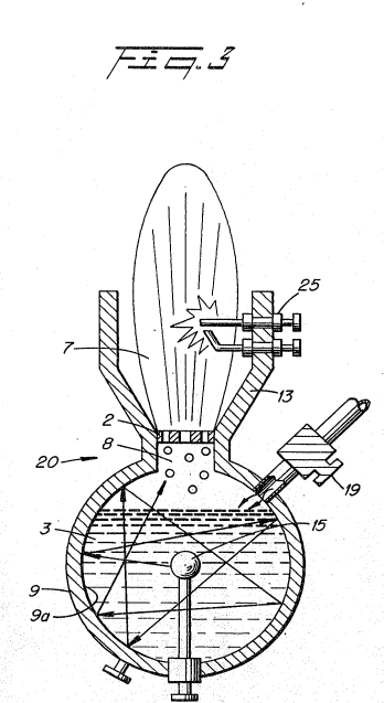](http://stanslegacy.com/uploads/images/gallery/2022-06/lfoSj348NLzKvLPx-screenshot-from-2022-06-25-01-03-46.png)In Figure 3 the resonant cavity structure 20 is utilized in a first completed self contained embodiment. Water 4 enters via nozzle 19 directly into the chamber of the closed sphere 9. The structure of Figure 3 is substantially identical in operation to that of Figure 1. However, in this embodiment, the opening 8 has a nozzle 2 therein with ports of selected size. The velocity of the gasses being expelled determines the sizes of the ports of the nozzle 2. ‘That is, the ports in the nozzle 2 must be sufficiently large to permit an adequate amount of gas to be expelled to maintain a flame, but not so small that the velocity of the gasses expelled would be so great that combustion cannot be sustained. The direction of the high velocity gasses is controlled by guide 13. The gasses 7. may be ignited by igniter 25 or utilized directly in another manner. The resonant cavities of Figures 1, 3, and 7 are related to the spacing between an outside and an inside spherical structure comprising a resonant cavity to the excited atoms .in the atomic process. Other configurations particularly those shown in the aforesaid co-pending patent application, may be constructed or modified to be resonant cavities. The resonant cavities will enhance the release of the gasses, irrespective of their configuration. However, the structure that is found most productive may be related to its utilization in an operable embodiment.| [](http://stanslegacy.com/uploads/images/gallery/2022-06/bByhlxezsgl28oj2-screenshot-from-2022-06-25-01-03-24.png) | [](http://stanslegacy.com/uploads/images/gallery/2022-06/lZ6f43kmSzeePYUU-screenshot-from-2022-06-25-01-04-17.png) |
The exciter 40 of Figure 6 is an improvement over an earlier development in that increased surface area is provided by corrugations in the walls that create the resonant cavity. The corrugations provide an enhancement of the sub-atomic action on the water entering at 44. The spacing 46 between the plate 41 and plate 42 is such that the cavity is resonant at a particular frequency, as aforementioned.
However, instead of a forward direct line back-and-forth path of the atom flow, the corrugations of the convex 47 and concave 49 surfaces cause the atoms to move in a forward and backward of back~and-forth path.The increased movement, in turn, increases the sub-atomic action and the velocity of the flow of gasses 45 emitted from the end 43 of exciter 40.
Referring now to Figures 7 and 7A, the structure of Figure 1 is in an array of resonant cavities 50a to 50n. Specifically, the housing 51 having water 52 therein includes the array of exciters, having a positive potential applied to its central element 53a to 53n, via terminal 64 and a negative potential to the outer element 55a to 55n.| [](http://stanslegacy.com/uploads/images/gallery/2022-06/lZ6f43kmSzeePYUU-screenshot-from-2022-06-25-01-04-17.png) | [](http://stanslegacy.com/uploads/images/gallery/2022-06/zXhKLjHmxVKzDSFP-screenshot-from-2022-06-25-01-04-12.png) |
| [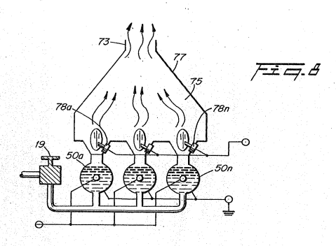](http://stanslegacy.com/uploads/images/gallery/2022-06/osYtj26wHQ29RYS8-screenshot-from-2022-06-25-01-04-20.png) | [](http://stanslegacy.com/uploads/images/gallery/2022-06/lfoSj348NLzKvLPx-screenshot-from-2022-06-25-01-03-46.png) |
In an explanation of the theory of operation of the invention a water molecule (H20) in a normal state has a molecular bond in a neutral molecule that includes the sharing of electrons between two nominally positive hydrogen atoms and a nominally negative oxygen atom. The molecule itself is in a neutral, uncharged, stable state.
In the invention, electrical voltage zones are created. The atoms of the normally neutral water molecule take on an electrical charge; the oxygen atom takes on a negative electrical charge; the hydrogen atoms take on a positive charge. The covalent electron bonding of the molecule is disrupted by the introduced electrical charge and is weakened. Separation of the atoms, and the production of gas, occurs between the plates. The process is preferably done in a non-chemical environment; thus, any form of "natural" water may be utilized without additives or chemicals. Voltage zones are provided by electrically conductive non-oxidizing, non-corrosive, non-reactive excitor plates (formed from a material such as stainless steel) placed in a non-chemical, non-reactive housing. A voltage is applied to the excitor plates to provide a potential energy.Although current leakage **will occur** because of the **residual conductivity of the water** in the invention the flow of amperes is limited deliberately in any well known manner so as to be insignificant. Contaminants present in water **do not affect** the process.
Gas production is achieved by pulsing the potential difference that creates the electrical voltage zones in a variable, repetitive manner. In general, the production of gas increases with either or both of the voltage applied and/or the frequency of: the voltage pulse. Because of the ability to control the gas production rate the method and apparatus of the invention provides a fuel cell that is a constant energy source. In practical application, there is no need for secondary storage medium for the gas produced. Natural water is the safest medium in which to store hydrogen atoms until they are needed for consumption. If the fuel cell is ruptured, the only material to spill out would be harmless water. ##### THE EMBODIMENTS OF THE INVENTION IN WHICH AN EXCLUSIVE PROPERTY OR PRIVILEGE IS CLAIMED ARE DEFINED AS FOLLOWS: 1\. A process for producing a gaseous medium which includes hydrogen and oxygen from water, comprising: > providing at least one pair of spaced apart electrically conductive, non-ox <idizing exciter elements in association with a cavity having a selected resonant frequency and in which there is water, said exciter elements being in ‘contact with the water in the cavity; > > applying a voltage potential to said exciter elements such that one element maintains a positive charge and the other a negative charge, and pulsing the voltage potential at a frequency matching the resonant frequency of the cavity. 2\. A process as set forth in claim 1 wherein one of said pair of exciter elements is a shell providing said cavity. 3\. A process as defined in claim 2 wherein said shell is a first sphere and wherein said other element is a second sphere, said second sphere being substantially smaller in size than said shell. 4\. A process as defined in claim 3 wherein said spherical shell includes a first and second spaced apart opening providing respectively a water inlet into the cavity and an outlet for the gases. 5\. A process as set forth in claim 1 including a plurality of pairs of exciter elements arranged in an array of ‘identical pairs. 6\. A process as set forth in claim 5 wherein the gases from the array of exciter elements are collected in a common chamber. 7\. A process as defined in claim 1 wherein said applied potential produces a gaseous medium in the cavity an including the step of regulating the output of the gaseous medium from said cavity. 8, A process for obtaining a gaseous medium which includes hydrogen and oxygen from water comprising > (a) providing a pair of electrically conductive non-oxidizing exciter elements in selected Spaced apart relation and arranged such as to provide a cavity therebetween which has a predetermined resonant frequency; > > {b) placing water in said-cavity; > > {c) applying an electrical voltage potential across said elements and pulsating the Same, without any change of polarity, at a frequency corresponding to said resonant frequency of the cavity; and > > (d) collecting the gases separated from the water in said cavity resulting from said applied pulsed voltage potential. 9\. Apparatus for producing a gaseous medium which includes hydrogen and oxygen from water comprising a first exciter element formed of an electrically conductive non-reactive material having a surface which defines the boundaries of a cavity, said cavity having a predetermined resonant frequency with a quantity of water therein, a second exciter element of the said same material within said cavity in selected spaced relationship from said first exciter element, means permitting the inflow of water into said cavity and means permitting the outflow of gases from said cavity, said gases being obtained from water in the cavity when an electrical pulsating potential is applied to said exciter elements. 10\. A process as set forth in claim 1 wherein the pair of exciter elements are coaxial and radially spaced providing therebetween said cavity and wherein the outermost element has an opening for the escape of gas from the cavity. 11\. An apparatus as set forth in claim 9 wherein said exciter elements are in a coaxial radial spaced relations, the space therebetween being said resonant cavity. 12\. An apparatus as defined in claim 11 wherein said coaxial arrangement is such that the cavity is closed at one end and open at the other opposite end. 13\. An apparatus as set forth in claim 9 further including igniter means for igniting the gases that outflow from said cavity. 14\. An apparatus as set forth in claim 9 including a plurality of said pairs of said exciter elements disposed side-by-side in an array. 15\. An apparatus as set forth in claim 14 including means to accumulate the gases output from the respective pairs of exciter elements in a common chamber. 16\. An apparatus as defined in claim 9 including a nozzle regulating the outflow of gases from said cavity. 17\. An apparatus as defined in claim 9 wherein said first exciter element is a spherical shell. 18\. An apparatus as defined in claim 17 wherein said second exciter element is spherical, 19\. An apparatus as defined in claim 18 wherein said spheres are concentric and radially spaced, the space between said spheres providing said cavity. 20\. An apparatus for producing a mixture of gases derived from water comprising a closed vessel suitable for maintaining a volume of water therein and permitting the addition of water thereto as the water therein is being depleted, means for providing an electrical potential difference within said vessel comprising a pair of electrically conductive exciter elements formed of the same non-reactive material positioned to be in the water in said vessel in a predetermined spatial relationship to one another to define a resonant cavity at a predetermined wavelength; a source of pulsating voltage potential that creates a potential difference between an arbitrary electrical ground and the source output in a waveform correlated to the predetermined resonance wavelength of the cavity; means for connecting one of said exciter elements to said arbitrary electrical ground and the other of said exciter elements to said source output, whereby there is formed during use of the apparatus a nominally positive electrical voltage zone in water adjacent the exciter element connected to said output and a’ nominally negative voltage zone in water adjacent the exciter element connected to said electrical ground as the pulsating voltage potential having the predetermined wavelength is applied thereto, the pulsating voltage potential during operation of said apparatus being applied to said exciter elements to a sufficient magnitude as to cause the electrical polarization of the water molecules in the vicinity thereof and to thereafter cause the hydrogen atoms of the water molecule to be attracted to said negative zone, and the oxygen atoms to be attracted to said positive zone, and thereby to create a resonance within the. cavity and weaken the bond between the hydrogen atoms and the oxygen atom so that said atoms disassociate from the water molecule and are released in the form of a gas mixture; and means for collecting and dispensing said mixture of gases. 21\. An apparatus as set forth in claims 3 or 20 including means to repetitively pulse direct current voltage potential across said exciter elements while maintaining a positive charge on one and a negative charge on the other and means to periodically interrupt said pulsing. 22, Apparatus as set forth in claims 9 or 20 wherein elements are non-oxidizing. # CA1213671A1 Electrical Particle GeneratorPDF Download: [SMeyer-CA1213671A1-Electrical\_Particle\_Generator.pdf](http://stanslegacy.com/attachments/47)
> Consumer and Consommation Corporate Affairs Canada et Corporations Canada > > (ll) (A) No 1213 671 > (45) ISSUED 861104 > (52) CLASS 353-14 C.R. CL. 355-1 > (51) INT, CL. HOLF 31/00,27/24as) ca) CANADIAN PATENT «2 > (54) Electrical Particle Generator > (72) Meyer, Stanley A., U.S.A. > (21) APPLICATION No. > (22) FILED > (30) PRIORITY DATE > > No. OF CLAIMS 420,909 830204 > U.S.A. (367,051) 820409 > DISTRIBUTED BY THE PATENT OFFICE, OTTAWA. CCA-274 (11-82). ## ELECTRICAL PARTICLE GENERATOR ### ABSTRACT An electrical particle generator comprising a non-magnetic pipe in a closed loop having a substantial amount of magnetized particles encapsulated therein. A magnetic accelerator assembly positioned on said pipe having an inductive primary winding and a low voltage input to said winding. A secondary winding positioned on said pipe opposite to said primary winding. Upon voltage being applied to said primary winding said magnetized particles are passed through said magnetic accelerator assembly with increased velocity. The velocity accelerated particles continuing through said pipe induce an electrical voltage/current potential as they pass through the secondary winding. The increased secondary voltage is utilized in an amplifier arrangement. ##### ##### BACKGROUND AND PRIOR ART The prior art teachings expound the fundamental principle that a magnetic field passing through inductive windings will generate a voltage/current or enhance the voltage there across if the winding is a secondary winding. It is also taught by the prior art that a magnetic element in a primary inductive field will be attracted at one end of the coil and repelled at the other. That is a moving magnetic — element will be accelerated in motion by the attraction and repulsion of the magnetic field of the primary inductive winding. In the conventional step-up transfer the voltage across the secondary is a function of the number of turns of the secondary relative to the number of primary turns. Other Factors are the size of the turns and whether the core is air or magnetic. ##### ##### SUMMARY OF INVENTION The present invention utilizes the basic principle of a particle accelerator and the principle of inducing a voltage in a secondary winding by passing a magnetic element there through. The structure comprises a primary voltage inductive winding having a magnetic forming core and a low voltage input. A secondary winding comprises a greater number of turns than the primary and has an output for utilization of the voltage induced therein. The primary inductive winding and core are positioned around a first position on an endless - closed loop, non-magnetic pipe. The secondary windings are positioned around an opposite position of said endless pipe. , The pipe is filled with discrete magnetic elements having a magnetic polarized charge placed thereon. The magnetic elements are particles and preferably gas. The magnetic elements due to their polarization will sustain some motion. As the particles approach the accelerator assembly, the primary coil, the field therein attracts the particles and accelerate the particles to enter the gap in the coil. As the magnetic element proceeds, the repulsion end of the accelerator will impart further magnetic force to the particles. This magnetic attraction and the repulsion considerably enhances - the motion of the discrete particles within the pipe. The particles are ejected from the area of the accelerator with | an increased velocity motion. The magnetic elements proceed in the closed Loop pipe at a speed considerably greater than their normal movement due to the accelerator action. As the magnetic elements pass through the core of the secondary winding there is induced a voltage therein. In this way a much greater voltage is induced in the secondary winding of the transformer. #### OBJECTS It is principal object of the present invention to provide an electrical generator capable of producing a voltage/current much greater in magnitude hereintofore possible. Another object of the present invention is to provide such an electrical generator utilizing magnetized elements and a magnetic accelerator. Another object of the present invention is to provide such an electrical generator that can control the amplitude of the output. Another object of the present invention is to provide such an electrical generator that may be utilized with direct current, alternating current, pulsed, or other configurations of waveforms. Another object of the present invention is to provide such an electrical generator that may be utilized in a single phase or three phase electrical system. Still another object of the present invention is to provide a generator for developing magnetized particles for use in an electrical particle accelerator. A further object of the present invention is to provide such an electrical generator that utilizes components readily available are adaptable to a simplified embodiment. Other objects and features of the present invention will become apparent from the following detailed description where taken in conjunction with the drawings in which: ##### BRIEF DESCRIPTION OF‘ DRAWINGS Figure 1 is a simplified illustration of the principles of the invention shown partly in cross-section and partly pictorially. [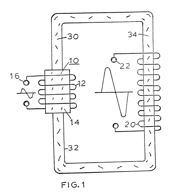](http://stanslegacy.com/uploads/images/gallery/2022-06/aOf2Nl3EPE3qsWFU-screenshot-from-2022-06-25-02-22-44.png) Figure 2 is an electrical schematic illustration of the embodiment of Figure 1. [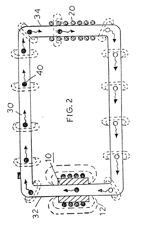](http://stanslegacy.com/uploads/images/gallery/2022-06/sMmdAIoXN7azDybF-screenshot-from-2022-06-25-02-22-52.png) Figure 3 is an illustration similar to Figure 2 but adaptable to 3 phase. [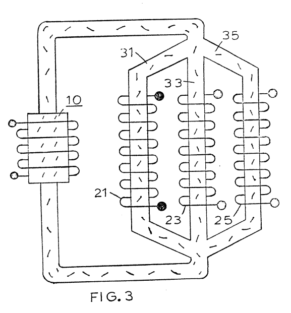](http://stanslegacy.com/uploads/images/gallery/2022-06/MUwT2t47CrWFXv2g-screenshot-from-2022-06-25-02-22-58.png) Figure 4 is a first alternative arrangement in a preferred illustration of the invention. [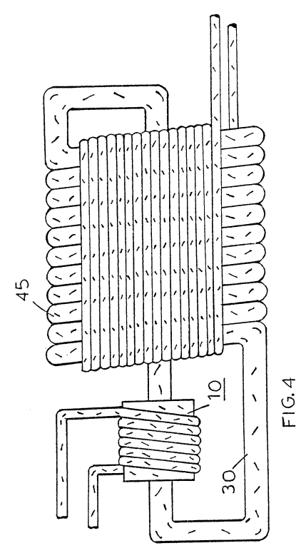](http://stanslegacy.com/uploads/images/gallery/2022-06/XrBZ9vS1GODYDRTr-screenshot-from-2022-06-25-02-23-03.png) Figure ‘5 is another alternative arrangement in a preferred illustration of the invention. [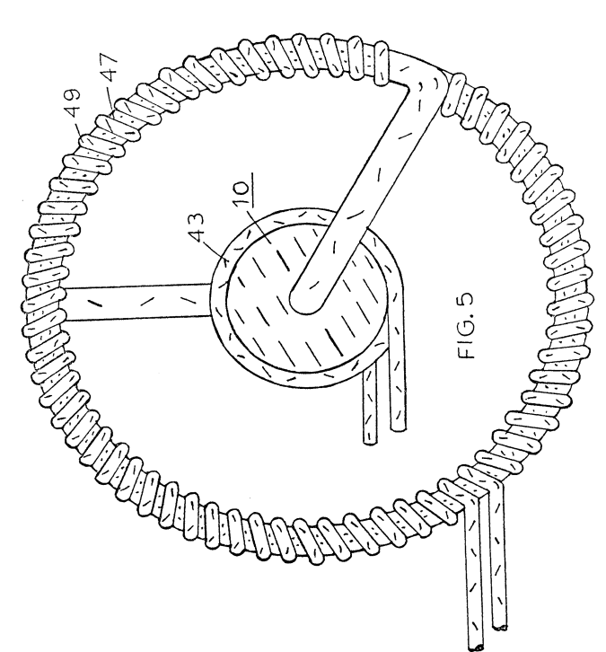](http://stanslegacy.com/uploads/images/gallery/2022-06/Z8GAiV8UgZGepH12-screenshot-from-2022-06-25-02-23-09.png) Figure 6 is another alternative arrangement in a preferred illustration of the invention. [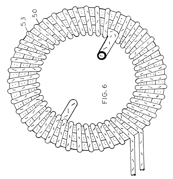](http://stanslegacy.com/uploads/images/gallery/2022-06/nXPiRYVFym3hs8OQ-screenshot-from-2022-06-25-02-23-30.png) Figure 7 is another alternative arrangement in a preferred illustration of the invention. [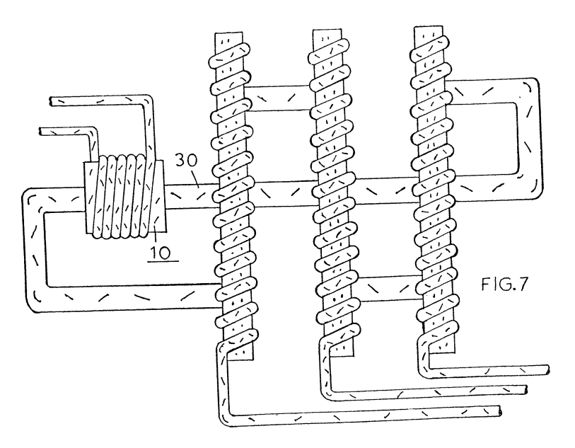](http://stanslegacy.com/uploads/images/gallery/2022-06/5fRVJwMT25cFlay0-screenshot-from-2022-06-25-02-23-40.png) Figure 8 is another alternative arrangement in a preferred illustration of the invention. [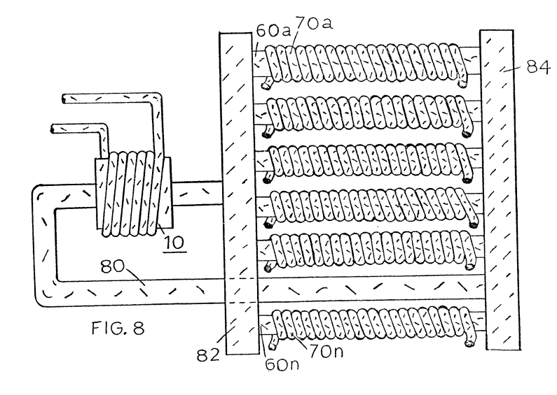](http://stanslegacy.com/uploads/images/gallery/2022-06/TT5FzjtIwcp4qB9D-screenshot-from-2022-06-25-02-23-46.png) Figure 9 is an alternative arrangement for a magnetic drive accelerator assembly. [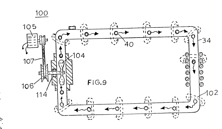](http://stanslegacy.com/uploads/images/gallery/2022-06/fpVyle7eCRQSNQVw-screenshot-from-2022-06-25-02-23-57.png) Figure 10 is a mechanical illustration of a magnetic particle generator for developing magnetic particles utilized in the present invention. ##### [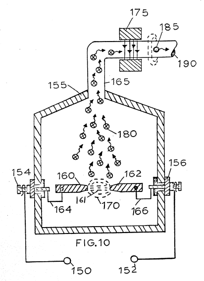](http://stanslegacy.com/uploads/images/gallery/2022-06/BCXPr8GkmFMCPLTo-screenshot-from-2022-06-25-02-24-07.png) ##### DETAILED DESCRIPTION OF INVENTION [](http://stanslegacy.com/uploads/images/gallery/2022-06/aOf2Nl3EPE3qsWFU-screenshot-from-2022-06-25-02-22-44.png)With particular reference to Figures 1 and 2 there is illustrated the invention in its mostly simplified schematic embodiment. The system of the invention comprises a primary winding coil magnetic accelerator assembly 10, a closed loop non-magnetic pipe 30, and a secondary winding 20. , The magnetic accelerator assembly comprises primary windings 12 a magnetic core 14 and voltage taps 16. The primary windings are positioned around end 32 of closed loop pipe 30 or tubing of non-magnetic material. At the opposite end 34 of the closed loop pipe 30 there is positioned thereon secondary windings 20. A voltage tap 22.on secondary winding 20 permits the utilization of the voltage induced therein. [](http://stanslegacy.com/uploads/images/gallery/2022-06/sMmdAIoXN7azDybF-screenshot-from-2022-06-25-02-22-52.png)Within the pipe 30 there is encapsulated a substantial quantity of magnetic elements 40 of Figure 2. The elements 40 must be sufficiently light to be freely mobile. Therefore, the elements may be particles suspended in a fluid medium such as gas, liquid, or light-weight movable solid particles and more preferably gas. In the application of suspended solid magnetic particles it may be desirable to evacuate the tubing to reduce the resistance to its flow. The magnetized elements 40 are discrete elements, that is, each particle or a minuscule part thereof is separately magnetized. Further, the action as hereinafter described is an action upon each particle and not upon the mass. | The voltage applied to terminals 16 of the primary winding 12 is a low voltage the magnitude of which may be utilized as an input signal control. By varying the input voltage the accelerator will vary the velocity of the speed of the particles; which, in turn vary the magnitude of the voltage/current output of the secondary winding 20. The output 22 of the secondary transformer 20 is a high voltage/current output. [](http://stanslegacy.com/uploads/images/gallery/2022-06/MUwT2t47CrWFXv2g-screenshot-from-2022-06-25-02-22-58.png)It can be appreciated that the system of Figures 1 and 2 utilizing a single closed loop will provide a single phase output in the secondary winding. With particular reference to Figure 3 there is illustrated a closed loop system having three parallel non-magnetic tubes 31, 33, and 35. On each tube or pipe there is a respective secondary winding 21, 23, and 25. Each of the secondary windings 21, 23, and 25 are a single phase much as that shown in Figures 1 and 2. The three pipes, having a common junction at its input and at its output, with the respective three secondary pick-up windings provide a balance three-phase (3) electrical system. [](http://stanslegacy.com/uploads/images/gallery/2022-06/XrBZ9vS1GODYDRTr-screenshot-from-2022-06-25-02-23-03.png)The electrical power generator illustrated in Figure 4 is in electrical operation identical to. that in Figures 1 and 2. The physical configuration of the arrangement is adapted to be utilized in a high moisture environment. An insulating coating 45 completely covers the pipe 30, as well as all electrical windings. In Figure 4 there is illustrated that increasing the number of coils‘with a given size winding the voltage/current output is increased. The physical configuration illustrated is such that the vertical aspects as well as the horizontal aspect are utilized. In this way a large diameter pipe can be used with a substantial number of turns of heavy-gauge high-current wire. [](http://stanslegacy.com/uploads/images/gallery/2022-06/Z8GAiV8UgZGepH12-screenshot-from-2022-06-25-02-23-09.png)With particular reference to Figure 5 there is illustrated a coil arrangement 49 that utilizes the entire magnetic flux in the closed loop tubing 47. The configuration is that of a coaxial arrangement with the primary winding 43 as a center core. Figure 6 illustrates a concentric spiral configuration of the tubing 50 having the secondary windings 53 wound over it's entirety.| [](http://stanslegacy.com/uploads/images/gallery/2022-06/nXPiRYVFym3hs8OQ-screenshot-from-2022-06-25-02-23-30.png) | [](http://stanslegacy.com/uploads/images/gallery/2022-06/5fRVJwMT25cFlay0-screenshot-from-2022-06-25-02-23-40.png) |
PDF Download: [SMeyer-CA1233379A1-Hydrogen\_Gas\_Injection\_for\_Internal\_Combustion\_Engine.pdf](http://stanslegacy.com/attachments/48)
> Consumer and Consummation Corporate Affairs Canada et Corporations Canace > > (a) (A) No. 1 233 379 > (45) ISSUED 880301 > (52) CLASS 123-15 C.R. CL. 60-14 > (51) INT. CL. FO2M 21/04as) can CANADIAN PATENT «2 > (54) Hydrogen Gas Injector for Internal Combustion Engine > (72) Meyer, Stanley A., U.S.A. > (21) APPLICATION No. 420,910 > (22) FILED B30204 > (30) PRIORITY DATE U.S.A. (349,185) 820217 No. OF CLAIMS 18 > > Canada > DISTRIBUTED BY THE PATENT OFFICE, OTTAWA. CCA-27-4 (11-82) ### ABSTRACT > A system and apparatus for the controlled intermixing of hydrogen gas with oxygen and other non-combustible gases in a combustion system is disclosed and can be used, for example, in an internal combustion engine. In the system, there is provided a hydrogen/oxygen generator, a water reservoir including a gas collection chamber, non-oxidizing plates in the reservoir and a direct current source connected to the plates for disassociation of hydrogen and oxygen atoms. The hydrogen gas is directed to a mixing chamber employing a fuel linear control valve. Non-combustible gas is also introduced into the mixing chamber and there is also ambient air intake means for combining air with the hydrogen gas and non-combustible gases. Controlled amounts of hydrogen gas combined with the non-combustible gas and ambient air are fed to the combustion chamber of the internal combustion engine. ##### ##### CROSS REFERENCES AND BACKGROUND There is disclosed in my co-pending Canadian Patent Application Serial No 420,908, filed February 4, 1983 for a Hydrogen-Generator, a generating system converting water into hydrogen and oxygen gases. In that system and method the atoms are dissociated from a water molecule by the application of a non-regulated, non-filtered, low-power, direct current voltage electrical potential applied to two non-oxidizing similar metal plates having water passing therebetween. The action is enhanced by pulsing the non-regulated and non-filtered direct current voltage. The apparatus comprises structional configurations in alternative embodiments for segregating the generated hydrogen gas from the oxygen gas. I have also devised a way whereby, non-combustible gases can be controlled in a mixing stage with a combustible gas. This hydrogen processor system utilizes a rotational mechanical gas displacement system to transfer, meter, mix, and pressurize the various gases. In the gas transformation process, ambient air is passed through an open flame gas-burner system to eliminate gases and other present substances. Thereafter the non-combustible gas-mixture is cooled, filtered for impurity removal, and mechanically mixed with a predetermined amount of hydrogen gas. The gas formation stage also volume meters and determines the proper gas-mixing ratio for establishing the desired burn-rate of hydrogen gas. The rotational mechanical gas displacement system in that process determines the volume-amount of gas to be produced. The above-noted hydrogen processor is a multi-stage system having a utility in special applications. Whereas the hydrogen generator system of my other mentioned co-pending application does disclose a very simple and unique hydrogen generator. I have also developed a combustion system having utility in a mechanical drive system. Particularly in one instance to drive a piston in’ an automotive device. It involves a hydrogen generator for producing hydrogen gas from water. The hydrogen gas with the attendant non-combustible gases are fed via a line to a controlled air intake system. The combined hydrogen, non-combustible gases, and the air after inter-mixing are fed to a combustion chamber where it is ignited. The exhaust gases of the combustion chamber are returned in a closed loop arrangement to the mixing chamber for the mixture of combustible and non-combustible gases. #### SUMMARY OF INVENTION The system of the present invention in its most preferred embodiment is for a combustion system utilizing hydrogen gas; particularly to drive a piston in an automobile device. The system utilizes a hydrogen generator for developing hydrogen gas. The hydrogen gas and other non-combustible gases are fed to a mixing chamber also having oxygen fed thereto. The mixture is controlled to regulate the burning temperature; that is, to lower the temperature velocity of the hydrogen gas to that of the commercial fuels. The hydrogen gas feed line to the combustion chamber includes a fine linear control gas flow valve. An air intake is the source of oxygen and it also includes a variable valve. The exhaust gasses from the combustion chamber are utilized in a controlled manner as the non-combustible gasses. The hydrogen generator is improved upon to include a holding tank to provide a source of start-up fuel. Also, the hydrogen gas generator includes switch to the power source operable from one position to another dependent upon a pressure sensing switch on the combustion chamber. The simplified structure includes a series of one-way valves, safety valves, and quenching apparatus. The combination of apparatus comprises the complete assembly for converting the standard automobile engine from gasoline (or other fuels) to the hydrogen gas mixture. #### OBJECTS It is, accordingly, a principal object of the present invention to provide a combustion system of gasses combined from a source of hydrogen and non-combustible gasses. Another object of the invention is to provide such a combustion system that intermixes the hydrogen and non-combustible gasses in a controlled manner and thereby control the combustion temperature. A further object of the invention is to provide such a combustion system that controls the Fuel flow to the combustion chamber in a system and apparatus particularly adapted to hydrogen gas. Still other objects and features of the present invention will become apparent from the following detailed description when taken into conjunction with the drawings in which: ##### BRIEF DESCRIPTION OF THE DRAWINGS Figure 1 is a mechanical schematic illustration partly in block form of the present invention in its most preferred embodiment. [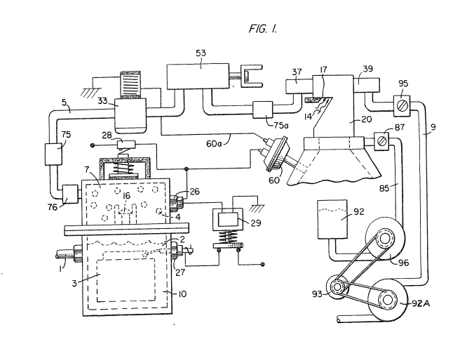](http://stanslegacy.com/uploads/images/gallery/2022-06/CfsvvPVg4tYTTdyK-screenshot-from-2022-06-25-11-56-08.png) Figure 2 is a block schematic illustration of the preferred embodiment of the hydrogen injector system of Figure l. [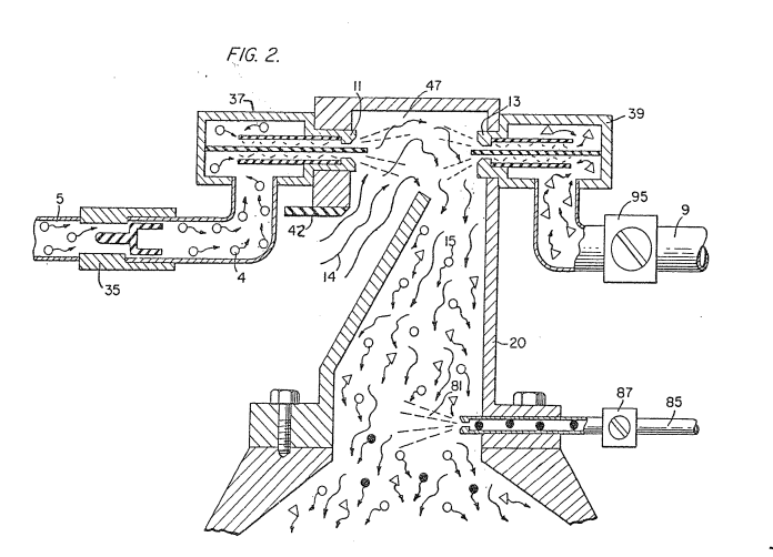](http://stanslegacy.com/uploads/images/gallery/2022-06/9hNIdN74SkUXSBgm-screenshot-from-2022-06-25-11-56-13.png) Figure 3 is the fine linear fuel flow control shown in Figure l. [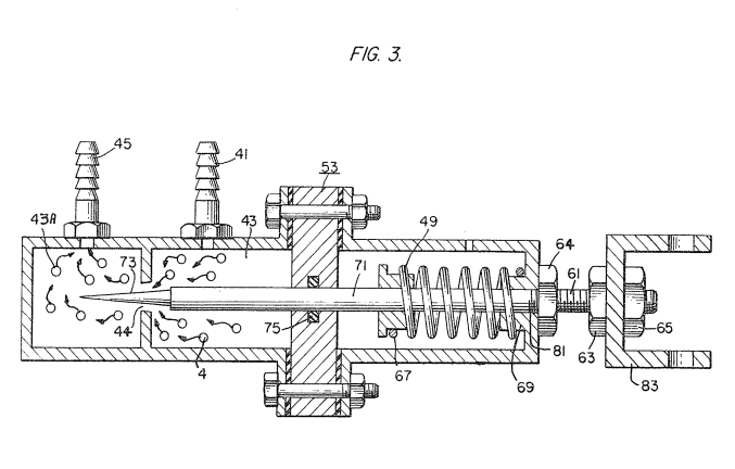](http://stanslegacy.com/uploads/images/gallery/2022-06/NPaNJek0ANjTnBxQ-screenshot-from-2022-06-25-11-56-18.png) Figure 4 is cross-sectional illustration of the complete fuel injector system in an automobile utilizing the concepts of the present invention. [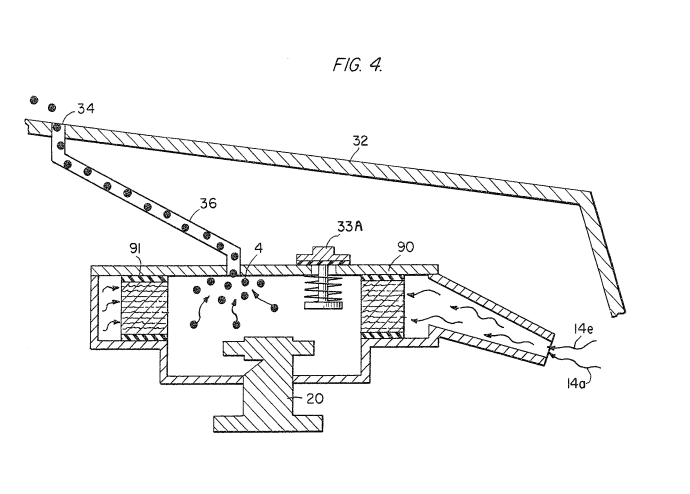](http://stanslegacy.com/uploads/images/gallery/2022-06/8WnPtOtoYpYQFZGZ-screenshot-from-2022-06-25-11-56-25.png) Figure 5 is a schematic drawing in a top view of the fuel injector system utilized in the preferred embodiment [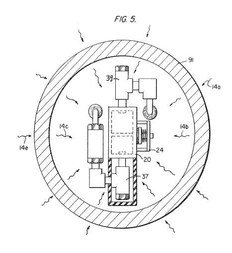](http://stanslegacy.com/uploads/images/gallery/2022-06/VTIogrf6BDIHw90J-screenshot-from-2022-06-25-11-56-30.png) Figure 6 is a cross-sectional side view of the fuel injector system in the present invention. [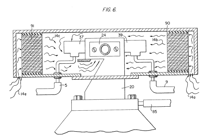](http://stanslegacy.com/uploads/images/gallery/2022-06/6TneLA8hVgxgxEaG-screenshot-from-2022-06-25-11-56-36.png) Figure 7 is a side view of the fuel mixing chamber. [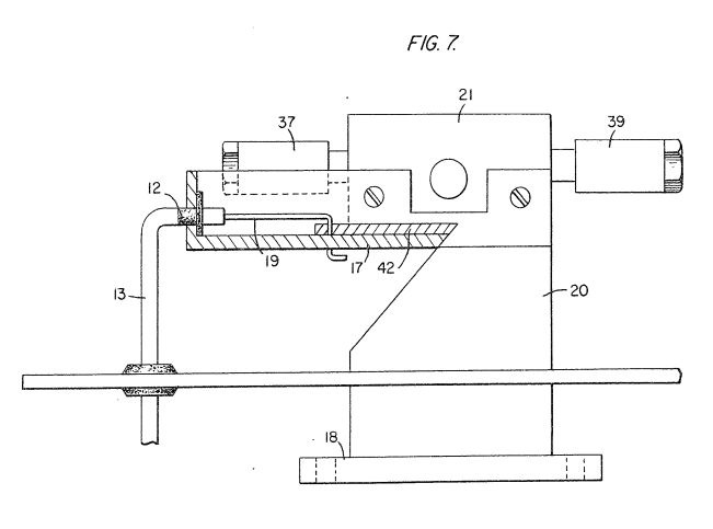](http://stanslegacy.com/uploads/images/gallery/2022-06/CLVOBq3cElHpMqMF-screenshot-from-2022-06-25-11-56-43.png) Figure 8 is a top view of the air intake valve to fuel mixing chamber. [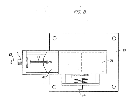](http://stanslegacy.com/uploads/images/gallery/2022-06/9BSQDTYvlAfN3iHz-screenshot-from-2022-06-25-11-56-48.png) Figure 9 is a graphical illustration of the adjustable burn-rate of hydrogen gas. [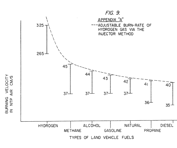](http://stanslegacy.com/uploads/images/gallery/2022-06/FAt8SU2WRkIuzTPz-screenshot-from-2022-06-25-11-28-45.png) ##### DETAILED DESCRIPTION OF INVENTION TAKEN WITH DRAWINGS [](http://stanslegacy.com/uploads/images/gallery/2022-06/CfsvvPVg4tYTTdyK-screenshot-from-2022-06-25-11-56-08.png)Referring to Figure 1, the complete overall gas mixing and fuel flow system is illustrated together for utilization in a combustion engine particularly an engine utilized in an automobile. With specific reference to Figure 1, the hydrogen source 10 is the hydrogen generator disclosed and described in my co-pending application, supra and includes a container which is an enclosure for a water bath 2 (natural water). Immersed in the water 2 is an array of plates 3 as further described in my co-pending application, supra and selectively applied (note solenoid 29) to plates 3 is a source of direct current potential via electrical inlet 27. The upper portion 7 of the container is a hydrogen storage area maintaining a predetermined amount of pressure. In this way for start up there will be an immediate flow of hydrogen gas. To replenish the expended water in the generator there is provided a continuous water source 1. Thereafter, the generator is operable as described in the aforesaid patent application. The safety valve 28 is rupture-able upon excessive gas build-up and switch 26 is a gas pressure switch to maintain a predetermined gas pressure level. The generated hydrogen gas 4 is fed from the one-way check valve 16 via pipe 5 to a gas mixing chamber 20, wherein the hydrogen gas is inter-mixed with non-combustible gasses that enter via pipe line 9 from a source hereinafter described. In the event one way valve 75 should fail and there be a return spark that might ignite the hydrogen gas 4 in the storage area 7 of hydrogen generator 10, quenching assembly 76 will quench the spark and prevent such ignition. With particular reference to Figure 2 the hydrogen gas via pipe line 5 and non-combustible gasses via pipe line 9 are fed to a carburetor (air-mixture) system 20 also having an ambient air intake 14. The hydrogen gas 4 is fed via line 5 through nozzle 11 in a spray into the trap area 47 of the mixing chamber 20. Nozzle 11 has an opening smaller than the plate openings in the quenching assembly 37, thereby preventing flash back in the event of sparking. The non-combustable gasses are injected into mixing chamber 20 trap area in a jet spray via nozzle 13. Quenching assembly 39 is operable much in the same manner as quenching assembly 37. The ambient air is, in the preferred arrangement, the source of oxygen necessary for the combustion of the hydrogen gas. Further, as disclosed in the aforesaid co-pending application the non-combustible gasses are in fact the exhaust gasses in a closed loop system. It is to be understood that the oxygen and/or the non-combustible gasses can be from an independent source. [](http://stanslegacy.com/uploads/images/gallery/2022-06/9hNIdN74SkUXSBgm-screenshot-from-2022-06-25-11-56-13.png)With continued reference to Figure 2 the gas trap area 47 is a predetermined size. In that hydrogen is lighter than air, the hydrogen will rise and become entrapped in the area 47. The size of area 47 is sufficient to contain enough hydrogen gas for instant ignition upon start up of the combustion engine. It will be noted that the hydrogen gas is injected in the uppermost region of the trap area 47. Hydrogen rises at a much greater velocity than oxygen or non-combustible gasses; perhaps three times or greater. Therefore, if the hydrogen gas entered the trap area 47 (mixing areas) at its lowermost region the hydrogen gas would rise so rapidly that the air could not mix with the oxygen. With the structure shown in Figure 2 of the trap area 47, the hydrogen gas is forced downwardly into the intake air. That is, the hydrogen gas is forced downwardly into the upwardly flowing air and readily mixed therewith. The ratio of the ambient air (oxygen) and the non-combustible gas via line 9 is a controlled ratio and determined by the particular engine. Once the proper combustion rate is determined by the adjustment of valve 95 for varying the amount of the non-combustible gas and the adjustment of valve iS for varying the amount of the ambient air, the ratio is maintained. In a system wherein the non-combustible gasses are the exhaust gasses of the engine in a closed loop arrangement and wherein the air intake is under the control of the engine, the flow velocity and hence the air/non-combustible mixture, is maintained by the acceleration of the engine. The mixture of air with non-combustible gasses becomes the carrier for the hydrogen gas. That is, the hydrogen gas is superimposed on the air/non-combustible mixture. By varying the amount of hydrogen gas superimposed 10 on the air/non-combustible mixture, the r.p.m. of the engine is controlled. [](http://stanslegacy.com/uploads/images/gallery/2022-06/NPaNJek0ANjTnBxQ-screenshot-from-2022-06-25-11-56-18.png)Reference is made to Figure 3 illustrating precisely in a side view cross-section the fine linear fuel flow control 53. The hydrogen gas 4 enters chamber 45 via gas inlet 41. The hydrogen gas passes from chamber 43 via port or opening 44. The amount of gas passing from chamber 43 to chamber 43A is controlled by controlling the port opening 44. The port opening is controlled by the insertion there through the linearly tapered pin 73. The blunt end of pin 73 is fixed to rod 71. Rod 71 passes through a supporting O-ring 75 and through an opening 81 in a housing to manual adjustment mechanism 83. The spring 49 retains the rod 71 in a fixed position relative to the pin 73 and opening 42. Upon actuating the mechanism 83, the pin 73 will recede from the opening 44 thereby increasing the amount of gas passing from chamber 43 to chamber 43A. The stops 67 and 69 maintain spring 49 in its stable position. The position of the pin 73 in a fixed position relative to opening 44 is adjusted via threaded nut 64 on threaded rod 61. That is, the threaded adjustment controls the idle speed or permits the minimum amount of gas to pass from chamber 43 to chamber 43A for continuous operation of the combustion engine. [](http://stanslegacy.com/uploads/images/gallery/2022-06/CLVOBq3cElHpMqMF-screenshot-from-2022-06-25-11-56-43.png)Referring now to Figures 7 and 8 there is illustrated the air adjustment control for manipulating the amount of air passing into the mixing chamber 20. The closure 21 mounted on plate 18 has air intake opening 17. Slide-ably mounted over said opening 17 is a plate control 42. The position of the plate relative to the opening 17 is controlled by the position of the control rod 19 passing through a grommet 12 to control line. In the event of malfunction that may cause combustion of gases in mixing chamber 20, release valve 24 will open. [](http://stanslegacy.com/uploads/images/gallery/2022-06/8WnPtOtoYpYQFZGZ-screenshot-from-2022-06-25-11-56-25.png)With reference now to Figure 4, in the event hydrogen gas 4 should accumulate in the mixing chamber 20 to excessive pressure, an escape tube 36 connected to a port 34 on the automobile hood 32 permits the excess hydrogen gas to safely escape to the atmosphere. In the event of a malfunction that may cause combustion in the mixing chamber 20, the pressure relief valve 33 will open expelling hydrogen gas without combustion. [](http://stanslegacy.com/uploads/images/gallery/2022-06/NPaNJek0ANjTnBxQ-screenshot-from-2022-06-25-11-56-18.png)In the constructed arrangement of Figure 1, there is illustrated a gas control system that may be retrofitted to an existing automobile internal combustion engine without changing or modifying automobile's design parameters or characteristics. The flow of the hydrogen gas is, of course, critical, therefore, there is incorporated in line 5 a gas flow valve 53 (Figure 1) to adjust the hydrogen flow. Gas flow valve is described in detail with reference to **Figure 3**. The air intake 14 may be in a carburetor arrangement with an intake adjustment that adjusts the 10 plate 5? and also more fully described with reference to Figure 8. To maintain constant pressure in hydrogen gas storage 7 in the on-off operation of the engine, the gas flow control valve is responsive to the electrical shut-off control 33. The constant pressure permits an abundant supply of gas on start up and during certain periods of running time in re-supply. The switch 33 is in turn responsive to the vacuum control switch 60. During running of the engine vacuum will be built up which in turn leaves switch 33 open by contact with vacuum switch 60 through lead 60a. When the engine is not running the vacuum will decrease to zero and through switch 60 will cause electrical switch 33 to shut off cutting off the flow of hydrogen gas to the control valve 53. As low-voltage direct current is applied to safety valve 28, solenoid 29 is activated. The solenoid applies a control voltage to the hydrogen generator plates 3 via terminal 27 through pressure switch 26. As the electrical power activates electric solenoid 29, hydrogen gas is caused to pass through valve 16 and then outlet pipe 5 for utilization. The pressure differential hydrogen gas output to gas mixing chamber 20 is for example 30 lbs. to 15 lbs. Once hydrogen generator 10 reaches an optimum gas pressure level, pressure switch 26 shuts off electrical power to the hydrogen generator plates. If the chamber pressure exceeds a predetermined level, the safety release valve 28 is activated disconnecting the electrical current and thereby shutting down the entire system for safety inspection. [](http://stanslegacy.com/uploads/images/gallery/2022-06/6TneLA8hVgxgxEaG-screenshot-from-2022-06-25-11-56-36.png)With particular reference now to Figure 6 there is illustrated the fuel injector system in a side cross-sectional view and to Figure 5 in a top view. The structural apparatus incorporated in the preferred embodiment comprises housing 90 having air intakes l4a and l4e. The air passes through filter 91 as indicated at 14b and 14c around the components and then to intake 17 of the mixing chamber 20. The hydrogen enters via line 5 via quenching plates in the quenching assembly 37 and into the mixing chamber 20. The non-combustible gasses pass via line 9 to the quenching plates of the quenching assembly 39 and into the mixing chamber 20. Figure 7 illustrates the mechanical arrangement of components comprising the overall structure of the mixing chamber 20 and shown independently in the other figures.| [](http://stanslegacy.com/uploads/images/gallery/2022-06/CLVOBq3cElHpMqMF-screenshot-from-2022-06-25-11-56-43.png) | [](http://stanslegacy.com/uploads/images/gallery/2022-06/CfsvvPVg4tYTTdyK-screenshot-from-2022-06-25-11-56-08.png) |
**PDF Download:** [SMeyer-CA1227094A1-Hydrogen\_Air\_&\_Non-Combustible\_Gas\_Mixing\_Combustion\_System.pdf](http://stanslegacy.com/attachments/49)
> .Consumer and Consummation - Corporate Affairs Canada at Corporations Canada > > (11) (a) No. 1 227 094 > (45) ISSUED 870922 > (52) CLASS 123-15 C.R. CL. 158-194 > (51) INT. CL. FO2M 21/04ag) ca CANADIAN PATENT «ez > (54) Hydrogen/Air and Non-Combustible Gas Mixing Combustion System > (72) Meyer, Stanley A., U.S.A. > (21) APPLICATION No. 420,889 (22) FILED 830204 No, OF CLAIMS al > > Canada > DISTRIBUTED BY THE PATENT OF CE, OTTAWA SCA27S \[1 1-82) i a ### ABSTRACT An internal combustion engine fuel supply and control that includes apparatus for disassociating hydrogen atoms and oxygen atoms from water and mixing the gas so produced with a non-combustible gas in a predetermined ratio. The gas mixture is mixed with air in suitable proportions and controllably directed to the combustion chamber of the internal combustion engine. ##### HYDROGEN COMBUSTION SYSTEMField of Invention This invention relates to a combustion system and more particularly to one where the combustible gas mixture is hydrogen, oxygen and non-combustible gases.
##### ##### Illustrations:| [](http://stanslegacy.com/uploads/images/gallery/2022-06/CfsvvPVg4tYTTdyK-screenshot-from-2022-06-25-11-56-08.png) | [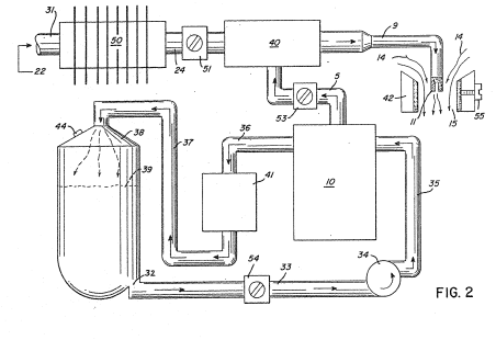](http://stanslegacy.com/uploads/images/gallery/2022-06/NPp61ykQR5nujaJR-screenshot-from-2022-06-25-12-36-24.png) | [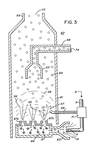](http://stanslegacy.com/uploads/images/gallery/2022-06/AnSHrZ9FQj7j3tKj-screenshot-from-2022-06-25-12-36-51.png) |
| [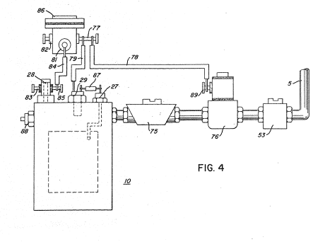](http://stanslegacy.com/uploads/images/gallery/2022-06/ruD25rwycYuz52ft-screenshot-from-2022-06-25-12-37-00.png) | [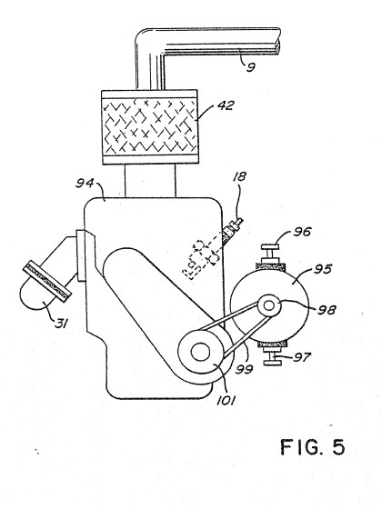](http://stanslegacy.com/uploads/images/gallery/2022-06/sVwmphBBUx3ugzOX-screenshot-from-2022-06-25-12-37-18.png) |
There is disclosed in my co-pending Canadian patent Application Serial No. 420,908, filed February 4, 1983, entitled "**A Hydrogen Generator**" a generating system converting natural water into hydrogen and oxygen gases.
In that system and method, the hydrogen atoms are disassociated from a water molecule by the application of a non-regulated, non-filtered, low-power, direct current voltage electrical potential applied to two non-oxidizing similar metal plates having water passing therebetween. The action is enhanced by pulsing the non-regulated and non-filtered direct current voltage. Particularly significant with my hydrogen generator disclosed in my co-pending application supra is that the hydrogen/oxygen generated is in a quantity in excess of that necessary for practical utilization.Further, **and equally significant** is that the generation of the hydrogen/oxygen is controlled by any one of or combination of several factors:
- varying voltage - varying pulse rate - varying spacing between plates - switching the number of plates - and changing the plate configurationThe hydrogen/oxygen generation is a demand system; that is, the hydrogen/oxygen is **generated only upon the need**. Then, the generation is controlled in quantity by the need; such as, accelerator for an automotive device.
In an earlier hydrogen processor, non-combustible gases are controlled in a mixing stage with a combustible gas. The hydrogen processor system utilizes a rotational mechanical gas displacement system to transfer, meter, mix, and pressurize the various gases. In the gas transformation process, ambient air is passed through an open flame gas burner system to eliminate gases and other present substances. Thereafter, the non-combustible gas-mixture is cooled, filtered for impurity removal, and mechanically mixed with a predetermined amount of hydrogen gas. The gas mixture provides the desired burn-rate. The rotational mechanical gas displacement system in that process determines the quantity by volume of combustible gas mixture to be produced.The above~noted hydrogen processor is a multi-stage system having utility in special applications. The aforementioned co-pending application discloses a very simple and unique hydrogen generator.
#### Summary of Invention The system of the present invention in its preferred embodiment is for a combustion system having utility in a mechanical drive system particularly, in one instance, to drive a piston in an automotive device. The system utilizes the hydrogen generator of my co-pending patent application Serial No. 420,908, for developing hydrogen gas, and other non-combustible gases such as oxygen and nitrogen. The hydrogen gas with the attendant non~combustible gases in a controlled ratio are fed via a line to a controlled air intake system. The combined hydrogen, non-combustible gases, and the air after intermixing are fed to a combustion chamber wherein the mixture is ignited. The exhaust gases of the combustion chamber are returned in a closed loop arrangement to the mixing chamber to provide the non-combustible gases for the mixture. More specifically, generated hydrogen gas is fed to a gas mixing chamber where it is intermixed with non-combustible gases and such gas mixture is then fed to a carburetor (air-mixture) system. The gas mixture is fed through nozzle means in a jet spray in a chamber and a valve or gate controls the amount of air intake to the jet spray. The gas mixture combines with the air to form a combustible mixture of hydrogen, non-combustible gas, and oxygen. The combustible mixture enters into a combustion chamber conventional in design and comprising a cylinder capable of withstanding high pressure. At the uppermost end of the combustion chamber is a spark plug igniter. #### #### Objects A principal object of the present invention is to provide a combustion system utilizing gases combined from a source of combustible and non-combustible gases. Another object of the invention is to provide a combustion system that utilizes hydrogen as the combustible gas and the exhaust of the combustion system as the non-combustible gas. A further object of the present invention is to provide a combustion system of the foregoing in a mechanical drive system. ##### ##### Brief Description of the Drawings: The invention is illustrated by way of example in the accompanying drawings wherein Figure 1 is a schematic, cross-sectional illustration of the present invention in its preferred embodiment; [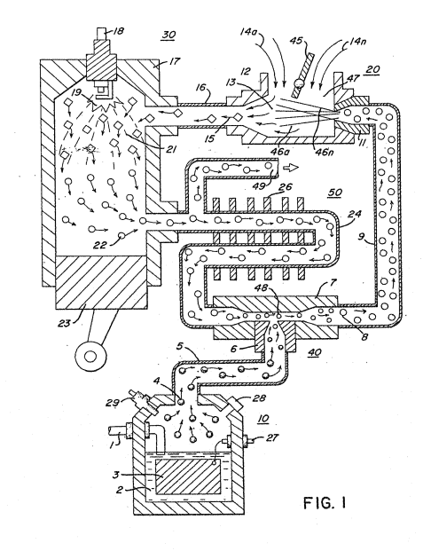](http://stanslegacy.com/uploads/images/gallery/2022-06/TuszVs8KSu0GDmDY-screenshot-from-2022-06-25-12-36-11.png) Figure 2 is a block schematic illustration of the preferred embodiment of Figure 1; [](http://stanslegacy.com/uploads/images/gallery/2022-06/NPp61ykQR5nujaJR-screenshot-from-2022-06-25-12-36-24.png) Figure 3 is an alternative gas system for that shown in Figure i; [](http://stanslegacy.com/uploads/images/gallery/2022-06/AnSHrZ9FQj7j3tKj-screenshot-from-2022-06-25-12-36-51.png) Figure 4 is a block schematic illustration of a gas control system for retrofitting existing automobiles to a combustion system of the present invention; and [](http://stanslegacy.com/uploads/images/gallery/2022-06/ruD25rwycYuz52ft-screenshot-from-2022-06-25-12-37-00.png) Figure 5 is a block schematic illustration of a regenerative energy feedback arrangement according to the present invention. ##### [](http://stanslegacy.com/uploads/images/gallery/2022-06/sVwmphBBUx3ugzOX-screenshot-from-2022-06-25-12-37-18.png) ##### Description of Preferred Embodiments of the Invention [](http://stanslegacy.com/uploads/images/gallery/2022-06/TuszVs8KSu0GDmDY-screenshot-from-2022-06-25-12-36-11.png)Referring particularly to Figure 1 the complete overall combustion system is illustrated together with a mechanical drive piston.Similarly, Figure 2 illustrates the complete system in its preferred embodiment.
[](http://stanslegacy.com/uploads/images/gallery/2022-06/NPp61ykQR5nujaJR-screenshot-from-2022-06-25-12-36-24.png) With particular reference to Figure 1, the hydrogen source 10 is the hydrogen generator disclosed and described in my aforementioned Application Serial No. 420,908 and includes an enclosure for a natural water bath 2. Immersed in the water 2 is an array of plates 3 of similar non-oxidizing material. Applied to plates 3 is a source of pulsed direct current potential via electrical inlet 27. The action of the pulsed direct current, a voltage/current potential, on the plates causes the hydrogen and oxygen atoms to become disassociated from the water molecule. In that the action is not a chemical action, any water irrespective of source may be utilized. Varying either the potential of the direct current source or the pulse rate of the pulsing of the direct current potential will vary proportionately the generation of the hydrogen/oxygen. Other factors are disclosed for varying the output of the generator. The water expended in the generator is replenished from continuous water source l. The hydrogen generator has a safety valve 28 which is rupturable upon excessive gas buildup, Switch 29 is a gas pressure switch to maintain a predetermined gas pressure level above a regulated low-volume. The generated hydrogen gas 4 is Fed via pipe 5 to a gas mixing chamber 7, wherein the hydrogen gas is intermixed with non-combustible gases 22 from a source hereinafter described. The mixture of combustible gas and non-combustible gases are fed via pipe line 9 to a carburetor (air-mixture) system 20. The gas mixture 8 is fed through nozzle 11 to chamber 47 in a jet spray 46. Valve or gate 45 in the air intake controls the amount of air the jet spray 46 of gases combines with to form combustible mixture 15 which comprise hydrogen, non-combustible gases and oxygen. This mixture enters into combustion chamber 30, via pipe line 16. The chamber 30 may be conventional in design comprising a cylinder 17 capable of withstanding high pressure. At the uppermost end of combustion chamber 30 is a Spark plug igniter 18. In a controlled manner, relative to the piston 23 stroke, the spark ignition 19 via plug 18 causes the mixed gases 15 to combust. The compression 21 caused by the combustion, forces the piston 23 to push downwardly in the cylinder 17. The exhaust gases 22, the residue of the combustion 21, now comprise a non-combustible mixture. A portion of these exhaust gases 22 are fed via pipe line 24 to the gas mixing chamber 40 providing the non-combustible gases for mixing with the generated hydrogen gas. The pipe line 24 passes through cooling chamber 50 far cooling of the gases therein. The cooling chamber 50 also functions as a spark arrestor to eliminate the possibility of gas ignition inside the mixing chamber 40. The excess non-combustible gases are exhausted via outlet 49, to be expelled into the atmosphere. [](http://stanslegacy.com/uploads/images/gallery/2022-06/NPp61ykQR5nujaJR-screenshot-from-2022-06-25-12-36-24.png)The apparatus of Figure 2 comprises much the same system as Figure 1. In this embodiment the components are depicted more explicitly in their structural relationship in an alternate arrangement. Basically, the system is operable in the same manner as that in Figure 1, i.e. it utilizes a mixture of combustible (hydrogen) gas and non-combustible gases (exhaust). The hydrogen generator 10, as aforesaid, may be any form of a generator, however, in the preferred embodiment the hydrogen generator is that of my aforementioned co-pending patent application. The water system for the generator is a closed loop system comprising a reservoir oer tank 39 with piping to and from the generator. The reservoir has an outlet 32 connected to a pipe line 33 provided with a water control valve 54 operable to adjust the water Flow rate and a pump 34 connected by pipe line 35 to the generator 10. The overflow water expended and non-expended is expelled from generator 10 into line 36, filtered in filter 41 to remove contaminants and returned to tank 39 via pipe line 37. The gases generated from the water in generator 10 also includes the oxygen component of the water in addition to nitrogen. The outlet 5 on the generator 10 receives the combustible (hydrogen)and non-combustible gases generated thereby and directs the same to the mixing chamber 40. The flow of the hydrogen gas is, of course, critical; therefore, there is incorporated in line 5 a gas Flow valve 53 to adjust the hydrogen gas flow. The exhaust gases entering input 22 are fed via inlet pipe 31 through the cooling chamber also enter the mixing chamber and spark arrestor 50 and into outlet pipe 24. These gases from chamber 50 are flow controlled by flow control valve 51 in pipe line 24. The output of mixing chamber 40, as described relative to Figure 1 is fed via line 9 to a gas mixture system 42. In this instance the intake air 14 may be in a carburetor arrangement with an intake adjustment 55 that adjusts the plate 42 opening. The gas mixture 15 is fad into the carburetor by nozzle 11 and mixed with the air 14. [](http://stanslegacy.com/uploads/images/gallery/2022-06/AnSHrZ9FQj7j3tKj-screenshot-from-2022-06-25-12-36-51.png)With particular reference to Figure 3 there is illustrated an alternative combustion chamber 60 that may be utilized in lieu of the chamber 30 of Figures 1 and 2. In this embodiment the combustible and non-combustible gas mixture that is generated and mixed in the arrangement of Figures 1 and 2, enters inlet 8 and is directed by pipe line 9 and nozzle 11 to the cone 65. The gas mixture combines with air 14 as it enters the cone area 65 and the combined mixture combustible gas 15 is directed by the cone 65 to the dispersing chamber 66. The gas/air mixture 15 is dispersed via ports 67a xxx 67n from the dispersing chamber 66 into the firing area of the combustion chamber 60. The gas mixture entering inlet 8 is also fed by pipe line 9 to a separation chamber 71. This chamber sections off a controlled amount of the intake gas mixture to a pilot light line 58. The pilot light firing gas 57 is also sequenced by the separation chamber 71 such as through an associated mechanical drive, much in the same manner as the cylinder of an automobile engine. The mixture designated gas 56, ejected from ports 67a xxx 67n of the dispersing chamber 66, is ignited by the pilot light and thereby causing combustion 59 of the mainstream gases, As the non-combustible gases 64 (exhaust gases 22 of Figure 1) rise upwardly in the cylinder 61, of the combustion chamber 60, the cone 63 captures a portion of the non-combustible gases 64. The captured exhaust gas is returned via pipe line 68 and outlet 74 to the combustion process as set in Figure 1 or expelled for other purposes. The major portion of the non-combustible gases 64 by-pass the cone 63 and rise further ta the outlet exhaust 69 and are expelled through opening 73. In Figure 4, there is illustrated a gas control system that may be retrofitted to an existing automobile internal combustion engine without changing or modifying its design parameters or characteristics. As low-voltage direct current is applied to safety valve 28, solenoid 86 is activated. ‘The solenoid applies a control voltage to the hydrogen generator plates 26 via terminal 27 through pressure switch 29. As the electrical power activates electric solenoid 86, hydrogen gas is caused to pass through flow adjustment valve 53 and then outlet pipe 5 for utilization. Gas regulator valve 75 is utilized to reduce the pressure level inside the hydrogen generator 10. The pressure differential hydrogen gas output to gas mixing chamber 40 is, for example, 30 lbs. to 15 lbs. Once hydrogen generator 10 reaches an optimum gas pressure level, pressure switch 29 shuts off electrical power to the hydrogen exciters. If the chamber pressure exceeds a predetermined level, the safety release valve 28 is activated disconnecting the electrical current and thereby shutting down the entire system for safety inspection. [](http://stanslegacy.com/uploads/images/gallery/2022-06/sVwmphBBUx3ugzOX-screenshot-from-2022-06-25-12-37-18.png)Similar to an automobile engine or other drive force requiring an electrical energizing source, the. present invention may include the regenerative energy feedback arrangement shown in Figure 5. The process utilizes a mechanical drive system as described relative to Figures 1 and 2; and which mechanical drive may be that of a piston such as utilized in a gasoline engine. In operation, the process mixture is ignited much in the same manner as in Figure 1. ‘The drive mechanism in turn activates electrical voltage of alternator 95 whose output is fed back to the hydrogen generator and utilized as the firing voltage on the spark plug 18; again, in a closed loop arrangement.| [](http://stanslegacy.com/uploads/images/gallery/2022-06/TuszVs8KSu0GDmDY-screenshot-from-2022-06-25-12-36-11.png) | [](http://stanslegacy.com/uploads/images/gallery/2022-06/NPp61ykQR5nujaJR-screenshot-from-2022-06-25-12-36-24.png) |
PDF Download: [SMeyer-CA1231872A1-Hydrogen\_Injection\_System.pdf](http://stanslegacy.com/attachments/50)
> Consumer and Consommation Corporate Affairs Canada et Corporations Canada > > (11) (A) No. > (45) ISSUED 880126 > (52) CLASS 123-154 > (51) INT. CL. FO2M 21/04aa) cs) CANADIAN PATENT 2) > (54) Hydrogen Injection System > (72) Meyer, Stanley A., U.S.A. > (21) APPLICATION No. 449,242 > (22) FILED 840309 > (30) PRIORITY DATE U.S.A. (478,207) 830323 No. OF CLAIMS 26 > > Canada > DISTRIBUTED AY THE PATENT OFFICE, OTTAWA. CCA-274 (14-82) ### ABSTRACT System and apparatus for the controlled intermixing ef hydrogen/oxygen gasses with non-combustible gasses to reduce the burning temperature and velocity of the hydrogen gas in a burner. The system utilizes a hydrogen generator for developing the hydrogen/oxygen gasses. The hydrogen gas with non- combustible gasses are intermixed in a controlled air intake chamber. The exhaust gasses of the burner are returned as the non-combustible gasses to the mixing chamber in a closed loop arrangement. Upon attaining the proper burning temperature and velocity of the hydrogen gas the ratio of hydrogen/oxygen and non-combustible gasses is maintained. To effect a practical utilization, the generation of the hydrogen/oxygen gasses are controlled in start-up and in quantity. The control of the generation of gasses is effected by one or more variable parameters; such as varying the voltage applied to the plates, varying the pulse rate of the voltage on the plates, varying the spacing between the plates, switching the number of plates, and plate configuration. The hydrogen/oxygen generation is on demand: that is the hydrogen/oxygen generation on start-up is only on demand and thereafter generation is controlled in quantity by the need much in the same manner as an accelerator. #### #### Illustrations| [](http://stanslegacy.com/uploads/images/gallery/2022-06/OXh9XxHOqzWYshBZ-screenshot-from-2022-06-25-13-14-06.png) | [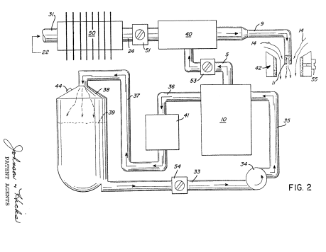](http://stanslegacy.com/uploads/images/gallery/2022-06/FFsKiFSllS9xVFRL-screenshot-from-2022-06-25-13-33-22.png) | [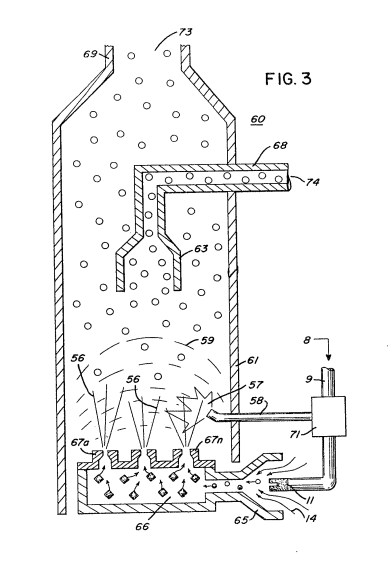](http://stanslegacy.com/uploads/images/gallery/2022-06/zWb3JvgiQwbUTPy9-screenshot-from-2022-06-25-13-34-08.png) |
| [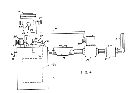](http://stanslegacy.com/uploads/images/gallery/2022-06/94SPmSQwSNWPYVUF-screenshot-from-2022-06-25-13-34-16.png) | [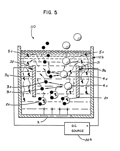](http://stanslegacy.com/uploads/images/gallery/2022-06/dnhgOM0K1dPtdmEN-screenshot-from-2022-06-25-13-34-32.png) | [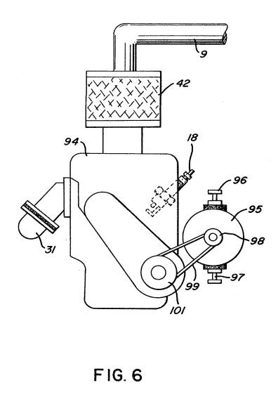](http://stanslegacy.com/uploads/images/gallery/2022-06/vdBeecqYkheFeTww-screenshot-from-2022-06-25-13-34-43.png) |
| [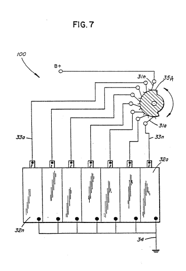](http://stanslegacy.com/uploads/images/gallery/2022-06/Qlxy1z4ndS9Rbvs6-screenshot-from-2022-06-25-13-34-49.png) | [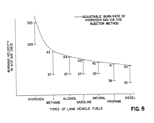](http://stanslegacy.com/uploads/images/gallery/2022-06/d0yFEer1v2FyiW6X-screenshot-from-2022-06-25-13-35-05.png) | [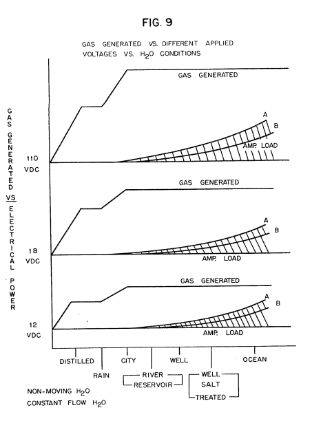](http://stanslegacy.com/uploads/images/gallery/2022-06/DwH59ndu7pKKinIx-screenshot-from-2022-06-25-13-35-46.png) |
| [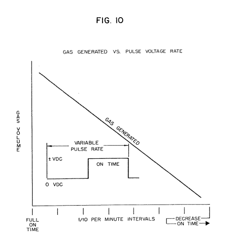](http://stanslegacy.com/uploads/images/gallery/2022-06/YRlBefR0xMts8tbN-screenshot-from-2022-06-25-13-35-52.png) | [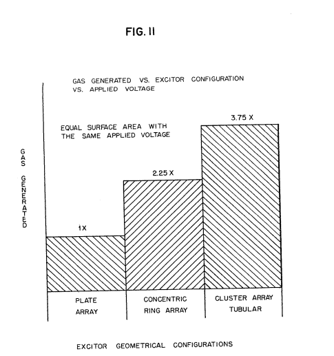](http://stanslegacy.com/uploads/images/gallery/2022-06/v20R5eyzEHvshYWi-screenshot-from-2022-06-25-13-35-57.png) | [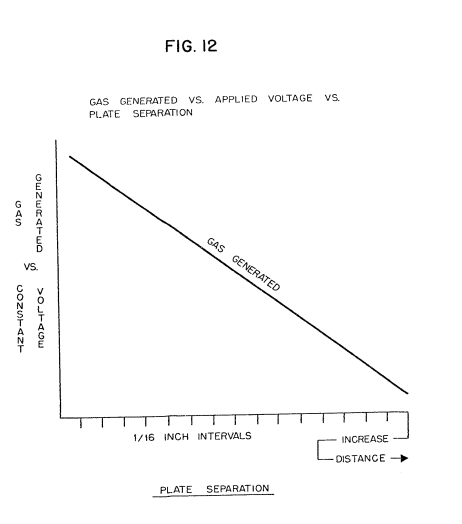](http://stanslegacy.com/uploads/images/gallery/2022-06/bipbdU24K77TZmBG-screenshot-from-2022-06-25-13-36-04.png) |
This application is related to my earlier filed Canadian patent Application Serial No. 420,889 filed February 4, 1983.
There is disclosed in my co-pending Canadian patent application, filed September 16, 1981, Serial No. 420,908 for a Hydrogen Generator, a generating system for converting natural water into hydrogen and oxygen gases.
In that system, the hydrogen atoms are disassociated from the water molecules by the application of a non-regulated, non-filtered, low power, direct current/voltage electrical potential applied to two non-oxidizing similar metal plates having natural non-electrolytic water passing therebetween. The action is enhanced by pulsing the non-regulated and non-filtered direct current/voltage. Particularly significant with the hydrogen generator disclosed in such application Serial No. 420,908, is that the hydrogen/oxygen generated is in excess of that necessary for practical utilization. Further, and equally significant, is that the generation of the hydrogen/oxygen is controlled by any one or more of several factors, i.e. varying voltage, varying pulse rate, varying spacing between plates, switching the number of plates, and plate configuration. Therefore, the hydrogen/oxygen generation of my co-pending patent application, supra and utilized in the preferred embodiment herein, is a demand system; that is, generation of the hydrogen/oxygen is initiated upon demand. Then, the generation of the hydrogen/oxygen is controlled in quantity by the need; such as, accelerator for an automotive device. Another earlier system utilizes a rotational mechanical gas displacement system to transfer, meter, mix, and pressurize the various gases. In the gas transformation process, ambient air is passed through an open flame gas-burner system to eliminate gases and other substances present. Thereafter, the non-combustible gas-mixture is cooled, filtered for impurity removal, and mechanically mixed with a pre-determined amount of hydrogen gas. The gas formation stage also meters the volume and determines the proper gas-mixing ratio for establishing the desired burn-rate of hydrogen gas. The rotational mechanical gas displacement system determines the volume-amount of gas to be produced. This is a multi-stage system having utility in special applications. The hydrogen generator system of the above-mentioned co-pending patent application discloses a very simple and unique hydrogen generator. ##### ##### SUMMARY OF INVENTION: The system of the present invention, in its most preferred embodiment, is for a combustion system having utility in a mechanical drive system, and particularly, in one instance, to drive a piston in an automotive device. The system utilizes the generator of my above-mentioned co-pending Application 420,908 for developing hydrogen gas, and other non-combustible gases such as oxygen and nitrogen. The hydrogen gas with the attendant non-combustible gases, in a controlled ratio, are fed via a line controlled air intake system. The combined hydrogen, non-combustible gases and the air, after intermixing, are fed to a combustion chamber wherein the mixture is ignited. The exhaust gases of the combustion chamber are returned in a closed loop arrangement to the mixing chamber. More specifically the generated hydrogen gas is fed to a gas mixing chamber wherein the hydrogen gas is intermixed with non-combustible gases. The mixture is fed to a carburetor (air intake mixture) system. The gas mixture is fed through nozzle means into a chamber in a jet spray. Valve or gate means controls the amount of air intake to the jet spray. The gases combine with the air to form a gas mixture of hydrogen, non-combustible gas, and oxygen. The mixture, now combustible but not as highly combustible as hydrogen by itself, is entered into a combustion chamber. The chamber may be conventional in design comprising a cylinder capable of withstanding high pressure and having a piston reciprocal therein. At the uppermost end of the combustion chamber there is a spark plug igniter. The exhaust gases, the residue of the combustion, now comprise a non-combustible mixture. These exhaust gases are fed to the gas mixing chamber as the non-combustible gases in a closed loop arrangement. To effect a practical utilization, the generation of the hydrogen/oxygen gases are controlled in start-up and in quantity. The control of the generation of gases is effected by one or more variable parameters; such as varying the voltage applied to the plates, varying the pulse rate of the voltage on the plates, varying the spacing between the plates, switching the number of plates, and plate configuration. The hydrogen/oxygen generation is on demand; that is, the hydrogen/oxygen generation on start- up is only on demand and thereafter generation of the gases is controlled in quantity by the need, much in the same manner as an accelerator. A principal object of the present invention is to provide a combustion system of gases combined from a source of combustible and non-combustible gases. A further object of the invention is to provide a hydrogen generator that is controllable in the generation of hydrogen/oxygen gases and therefore capable ef controlling the rate of firing of a burner system. A further object of the invention is to provide a hydrogen generator and combustion system that may be incorporated in a mechanical drive system. In keeping with the foregoing, there is provided in accordance with the present invention a burner system comprising: a hydrogen/oxygen generator; a housing having a water reservoir for retaining water therein having no electrolyte added thereto; a pair of similar electrical voltage conductive non-oxidizing, non-corrosive, non-reactive plates positioned in said water reservoir in spaced apart relation with respect to one another; a direct current voltage source having positive and negative output terminal connected to respective ones of said pair of plates to apply a low current electrical voltage for disassociating the hydrogen gas atoms and oxygen gas atoms from the water molecules; and a gas mixing chamber; conduit means including first control valve connecting the hydrogen/oxygen combustible gases from said hydrogen/oxygen generator to said mixing chamber; a source of non-combustible gas; conduit means including a second control vaive connecting the non-combustible gas from said non-combustible source to said mixing chamber; said combustible gas and non-combustible respective first and second gas control valves regulating the gas mixture ratio of combustible/non-combustible gases from said mixing means; air-intake means connected to the output of said mixing chamber for combining air with said mixed gases; a gas burner having said controlled amount of mixed gases from said mixing chamber and air mixed therewith fed thereto; means to ignite said gas/air mixture in said gas burner; and demand control means for varying the release of said hydrogen/oxygen gas atoms to thereby accelerate and decelerate the rate of ignition of said gas/air mixture. ##### ##### BRIEF DESCRIPTION OF THE DRAWINGS The invention is illustrated by way of example in the accompanying drawings wherein: Figure 1 is a schematic cross-sectional illustration of one embodiment of the present invention; [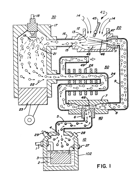](http://stanslegacy.com/uploads/images/gallery/2022-06/pCMa1tUzZrkzFCmK-screenshot-from-2022-06-25-13-14-06.png) Figure 2 is a block schematic illustration of the preferred embodiment of Figure 1; [](http://stanslegacy.com/uploads/images/gallery/2022-06/FFsKiFSllS9xVFRL-screenshot-from-2022-06-25-13-33-22.png) Figure 3 is an alternative gas system replacement for that shown in Figure 1; [](http://stanslegacy.com/uploads/images/gallery/2022-06/zWb3JvgiQwbUTPy9-screenshot-from-2022-06-25-13-34-08.png) Figure 4 is a block schematic illustration of a complete drive system utilizing the concepts of the present invention; [](http://stanslegacy.com/uploads/images/gallery/2022-06/94SPmSQwSNWPYVUF-screenshot-from-2022-06-25-13-34-16.png) Figure 5 is a basic schematic drawing of the hydrogen generator utilized in the preferred embodiment as the motive force in a drive system; [](http://stanslegacy.com/uploads/images/gallery/2022-06/dnhgOM0K1dPtdmEN-screenshot-from-2022-06-25-13-34-32.png) Figure 6 is a further application of the present invention in a regenerative energy feedback system; [](http://stanslegacy.com/uploads/images/gallery/2022-06/vdBeecqYkheFeTww-screenshot-from-2022-06-25-13-34-43.png) Figure 7 illustrates the voltage potential as applied to several plates; [](http://stanslegacy.com/uploads/images/gallery/2022-06/Qlxy1z4ndS9Rbvs6-screenshot-from-2022-06-25-13-34-49.png) Figure 8 is a graph illustration of the burning velocity of standard fuels for a land vehicle; [](http://stanslegacy.com/uploads/images/gallery/2022-06/d0yFEer1v2FyiW6X-screenshot-from-2022-06-25-13-35-05.png) Figure 9 is a graphical illustration of gas generated versus different applied power, for various types of water conditions; [](http://stanslegacy.com/uploads/images/gallery/2022-06/DwH59ndu7pKKinIx-screenshot-from-2022-06-25-13-35-46.png) Figure 10 is a graph illustrating gas generated versus pulse direct current repetition rate; [](http://stanslegacy.com/uploads/images/gallery/2022-06/YRlBefR0xMts8tbN-screenshot-from-2022-06-25-13-35-52.png) Figure 11 is a graphical illustration of gas generation for three different geometrical configurations of plate structure; and [](http://stanslegacy.com/uploads/images/gallery/2022-06/v20R5eyzEHvshYWi-screenshot-from-2022-06-25-13-35-57.png) Figure 12 is a graphical illustration of gas generated with the plates having increasing separation. ##### [](http://stanslegacy.com/uploads/images/gallery/2022-06/bipbdU24K77TZmBG-screenshot-from-2022-06-25-13-36-04.png) ##### DESCRIPTION OF PREFERRED EMBODIMENTS Figure 1 illustrates a complete overall combustion system together with a piston and cylinder of an internal combustion engine.Similarly, Figure 2 illustrates the complete system in its preferred embodiment.
[](http://stanslegacy.com/uploads/images/gallery/2022-06/FFsKiFSllS9xVFRL-screenshot-from-2022-06-25-13-33-22.png) With particular reference to Figure 1, the hydrogen source 10 is the hydrogen generator disclosed and described in my co-pending application, supra. The container 102 is an enclosure for a natural water bath 2. Immersed in the water 2 is an array of plates 3 of similar non-oxidizing material. Applied to plates 3 is a source of pulsed direct current potential via electrical inlet 27. [](http://stanslegacy.com/uploads/images/gallery/2022-06/pCMa1tUzZrkzFCmK-screenshot-from-2022-06-25-13-14-06.png)The action of the pulsed direct current, a voltage/current potential, on the plates causes the hydrogen and oxygen atoms to become disassociated from the water molecule. Varying either the potential of the direct current source or the pulse rate of the pulsing of the Girect current potential will vary proportionately the generation of the hydrogen/oxygen. Other factors are disclosed for varying the output of the generator. More specifically with reference to Figure 5, to be taken in conjunction with the generator 10, of Figure l, there is illustrated schematically in cross-section the hydrogen/oxygen generator in its most simplified embodiment. The container 102 holds supply of water 2 which is natural water and can be either pure distilled water, or salt, or tap, well, rain, river, or other water containing contaminants. However, specifically, no electrolyte or chemicals are added to the water. The water 2, comprising molecules 2a xxx 2n of hydrogen 3a xxx 3n, oxygen 4a Xxx 4n, and foreign substances 5a xxx 5n, is passed between a pair of plates 9a and 9b, consisting of similar non-oxidizing metal, submerged therein. To replenish the expended water the generator is connected via line 1 to a suitable water source. Attached to terminal 32 on plates 9a is a wire having its other end connected to the negative terminal, and to terminal 31 on the plate 9b is connected another wire having its other end connected to the positive terminal of the direct current electrical source 30A. The direct current voltage applied to the water passing between plates 9a and 9b, is sufficient to disassociate the hydrogen atoms and oxygen atoms (appearing as bubbles) from the water molecules. The foreign substance or contaminants are broken away from the water molecule and spillover the outside areas of the plates 9a and 9b to a collector at the bottom cf the container 102. The hydrogen gas and oxygen gas rises above the liquid. [](http://stanslegacy.com/uploads/images/gallery/2022-06/DwH59ndu7pKKinIx-screenshot-from-2022-06-25-13-35-46.png)As illustrated in Figure 9, increasing the voltage applied to the plates 9a and 9b enhances the action upon the water molecule, which in turn increases the hydrogen/oxygen gas generation. **The gas generated is substantially a linear function to the magnitude of the voltage applied to the plates**. Therefore, by increasing or decreasing the direct current voltage potential applied to the plates the hydrogen/oxygen rate of generation is directly related. Also, and most significantly, the voltage is increased and decreased but the current is maintained constant at a very low level. That is, the direct current voltage potential is current limited. As shown in Figure 10, it has also been found that pulsing the voltage applied to the plates 9a and 9b enhances the action upon the water molecule, which in turn increases the hydrogen/oxygen gas generation. The gas generated is a linear function to the pulse repetition rate of the voltage applied to the plates 9a and 9b. A safety release valve 28 is used to avoid excessive gas buildup and the switch 29 is a gas pressure switch to maintain a predetermined gas pressure level. The generated hydrogen gas 4 is fed via pipe 5 to a gas mixing chamber 40, wherein the hydrogen gas is inter-mixed with non-combustible gases such as, for example, exhaust gases 22 as more fully discussed hereinafter. [](http://stanslegacy.com/uploads/images/gallery/2022-06/YRlBefR0xMts8tbN-screenshot-from-2022-06-25-13-35-52.png)The mixture of combustible gas and non-combustible gases are fed via pipe line 9 to a carburetor (air-mixture) system 20. The gas mixture 8 is fed through nozzle 11 to chamber 47 in a jet spray 46. Valve or gate 45 controls the amount of air-intake which combines with the gas mixture of jet spray 46. The mixture of air, hydrogen and non-combustible gases enters combustion chamber 30, via pipe line 16. The chamber 30 may be conventional in design and comprises a cylinder 17 capable of withstanding high pressure. At the uppermost end of the combustion chamber 30 is a spark plug igniter 18. In a controlled manner, relative to the piston 23 stroke, the spark ignition 19 via spark plug 18, causes the mixed gases to combust. The compression 21 caused by the combustion forces the piston 23 to push downwardly in the cylinder 17. The exhaust gases 22, the residue of the combustion 21, now comprises a non-combustible mixture. These exhaust gases 22 are fed via pipe line 24 to the gas mixing chamber 40 as the non-combustible gases as aforesaid. The pipe line 24 passes through cooling chamber 50 for cooling of the gases therein. The cooling chamber 50 also functions as a spark arrestor to eliminate the possibility of gas ignition inside the mixing chamber 40. The excess non-combustible gases are exhausted via outlet 4g, to be expelled into the atmosphere. [](http://stanslegacy.com/uploads/images/gallery/2022-06/FFsKiFSllS9xVFRL-screenshot-from-2022-06-25-13-33-22.png)The apparatus of Figure 2 comprises much the same system as Figure 1. In this embodiment the components are depicted more explicitly in their structural relationship in an alternate arrangement. Basically, the system is operable as that in Figure 1, i-e. a mixture of combustible (hydrogen) gas and non-combustible gases (exhaust). The hydrogen generator 10, as aforesaid, may be any form of a generator, however, in the preferred embodiment the hydrogen generator is that of my co-pending application, supra. The water system in a closed loop operation comprises a reservoir or tank 39 with an outlet having pipe line 33 connected thereto, water control valve 54 being operable to adjust the water flow. The water is pumped by pump 34 in line 33 to line 35, and then to the generator 10. The overflow water expended and non-expended is expelled from generator 10 into line 36, filtered in filter 41 of contaminants, and returned to tank 39 via pipe line 37. The loop is completed. The gases generated from the water in generator 10 also includes the oxygen component of the water in addition to nitrogen. The outlet 5 on the generator 10 receives the combustible and non-combustible (oxygen and nitrogen) gases generated thereby and feeds the same to the mixing chamber 40. The flow of the hydrogen gas is, of course; critical; therefore, there is incorporated in line 5 a gas flow valve 53 (Fig. 2) to adjust the hydrogen flow. The exhaust gases 22 are fed via inlet pipe 31 to the cooling and spark arrestor chamber 50 and by pipe 24 into the mixing chamber 40. These gases from cooling and spark arrestor chamber 50 to mixing chamber 40 are controlled by a flow control valve 51 in pipe line 24. The output of gases from mixing chamber 40 as described relative to Figure 1 and 2 is fed via line 9 to an air/gas mixture system 42. In this instance, the intake air 14 may be in a carburetor arrangement with an intake adjustment 55 that adjusts a plate on an air intake opening of the air/gas mixture system 42. The gas mixture is fed into the carburetor by nozzle 11 and mixed with the air 14. [](http://stanslegacy.com/uploads/images/gallery/2022-06/zWb3JvgiQwbUTPy9-screenshot-from-2022-06-25-13-34-08.png)With particular reference to Figure 3 there is illustrated an alternative combustion chamber 60 that may be utilized in lieu of the chamber 30 of Figure l. In this embodiment the combustible and non-combustible gas mixture that is generated and mixed in the arrangement of Figures 1 and 2, enters inlet 8 and is directed by pipe line 9 and nozzle 11 to the cone 65. The gas mixture combines with air 14 as it enters cone areas 65. The combined gas mixture is directed by the cone 65 to the dispersing chamber 66. There the gas mixture is further mixed with air 14 to form combustible gas- The gas/air mixture is dispersed via ports 67a XXX 67n from the dispersing chamber 66 into the firing area of the combustion chamber 60. The gas mixture entering inlet 8 is also fed by pipe line 9 te a separation chamber 71. This chamber sections off a controlled amount of the intake gas mixture to the pilot light line 58. The pilot light firing 57 is sequenced by the drive, much in the same manner as the cylinder of an automobile engine. The mixed .gas designated 56a, 56n, ejected from ports 67a XxX 67n of the dispersing chamber 66 is ignited by the pilot light combustion 57 in the firing area of the combustion chamber and thereby causing combustion 59 of the mainstream gases. As the non-combustible gases (exhaust gases 22 of Figure 1) rise upwardly in the cylinder 61, of the combustion chamber 60 the cone 63 captures a portion of such non-combustible gases. The captured exhaust gas is returned via pipe line 68 and outlet 74 to the combustion process as set in Figure Ll or expelled for other purposes. The major portion of the non-combustible gases by-pass the cone 63 and rise further to the outlet exhaust 69 and are expelled at opening 73. [](http://stanslegacy.com/uploads/images/gallery/2022-06/94SPmSQwSNWPYVUF-screenshot-from-2022-06-25-13-34-16.png)In the constructed arrangement of Figure 4, there is illustrated a gas control system that may be retrofitted to an existing automobile internal combustion engine without changing or modifying its design parameters or characteristics. As low-voltage direct current is applied to safety valve 28, solenoid 86 is activated. This results in applying a control voltage to the hydrogen generator plates 3 via terminal 27 through pressure switch 29. Hydrogen gas produced in hydrogen generator 10 passes through flow adjustment valve 53 and then outlet pipe 5 for utilization. Gas regulator valve 75 is utilized to reduce the pressure level inside hydrogen generator 10. The pressure differential hydrogen gas output to gas mixing chamber 40 is, for example, 30 lbs. to 15 lbs. Once hydrogen generator 10 reaches an optimum gas pressure level, pressure switch 29 shuts off electrical power to the hydrogen excitors. If the chamber pressure exceeds a predetermined level, the safety release valve 28 is activated disconnecting the electrical current and thereby shutting down the entire system for safety inspection. Similar to an automobile engine or other drive force requiring an electrical energizing source, the present invention may include the regenerative energy feedback arrangement shown in Figure 6. The process utilizes a mechanical drive system as described relative to Figures 1 and 2; and which mechanical drive may be that of a piston such as utilized in a gasoline engine. In operation, the process mixture is ignited much in the same manner as in Figure 1. The drive mechanism in turn activates electrical voltage of alternator 95 whose output is fed back to the hydrogen generator and utilized ag the firing voltage on the spark plug 18; again, ina closed loop arrangement. The ratio of hydrogen/oxygen gases is varied to obtain optimum burning velocity and temperature for the particular combustion engine. Once this is attained, the ratio, under normal conditions, will not be altered. Other engines having different fuel burn temperature and velocity will be adjusted in ratio of hydrogen/oxygen to non-combustible gases in the same manner as exemplified above. [](http://stanslegacy.com/uploads/images/gallery/2022-06/d0yFEer1v2FyiW6X-screenshot-from-2022-06-25-13-35-05.png)With reference to Figure 8 there is illustrated the burning velocity of various standard fuels. It can be seen the common type of fuel for a land vehicle burns at a velocity substantially less than with hydrogen gas. In an application of the preferred embodiment to the present invention i.e., an automobile, the proper burning velocity and temperature will be attained as aforesaid, to match that of the gasoline burning engine, the burning engine or its particular fuel. This ratio once attained will not be altered. In operation of the engine, when the engine is not running, there is no tank of hydrogen fuel in the automobile, such as suggested by the prior art. Applicant's automobile simply has a tank of water. Upon start-up, hydrogen/oxygen from the tank of water is immediately generated, and ignition takes place. Again, only enough hydrogen/oxygen is generated to effect combustion. [](http://stanslegacy.com/uploads/images/gallery/2022-06/Qlxy1z4ndS9Rbvs6-screenshot-from-2022-06-25-13-34-49.png)Further, in operation of the automobile utilizing the present invention, when it is desired to accelerate the firing rate of the engine, such as may occur in normal driving, the rate of generation of the hydrogen/oxygen is accelerated by the demand controls. The greater demand for acceleration, the greater the generation of the gases. ~ Again, in the practical working embodiment of the automobile utilizing the hydrogen/oxygen engine of the present invention, the "throttle" for accelerating the speed of the engine will be an electronic control. This may be such as for varying the pulse rate or the magnitude of the voltage of the direct current voltage potential applied to the plates of the generator. tn lieu of increasing the electrical power or varying the pulse rate to enhance the action on the water molecules, other conditions have been considered. With particular reference to Figure 7 there is illustrated an electronic switch for switching on and off the rippled d.c. output of supply 30a. The plates 32a xxx 32n are connected to common ground 34. The positive terminals 33a xxx 33n are connected respectively to contacts 3la xxx 3ln of switch 35a rotatively making and breaking contact with the direct/current voltage source 30a. It can be appreciated the greater the number of cells the more hydrogen/oxygen generated. Ina practical embodiment, the combustion engine is started on a minimum number of cells. Upon acceleration, the greater the need for more hydrogen/oxygen gas, hence the increase in the number of cells. In this way, the switch 35a is an accelerometer. Again, in that the increase in generation of hydrogen/oxygen by the actuation of switch 35a, the increase is a step function. It is deemed desirable therefore, that the configuration of switch control of cells be in conjunction with the aforesaid linear type of acceleration. Other structure factors altering, affecting, and particularly enhancing the hydrogen gas generating comprises altering plate spacing, and the plate configuration. Each of these factors have been taken into consideration in the development of a fuel cell to provide optimum results for a preferred embodiment. As stated above, another factor affecting the gas generation ouput is the plate separation. With particular reference to Figure 12 there is illustrated graphically plate spacing versus gas generation. As can be seen, the greater the spacing the less gas generation. The efficiency versus spacing of the plates is a linear decrease with spacing. With particular reference to Figure 11, there is illustrated graphically the efficiency of the tubular plate array, the cluster tubular array, and the flat plate array- Specifically there is shown the gas generation versus the plate configuration. Although the invention in its preferred embodiment is best exemplified in an internal combustion engine, it can be envisioned that the concepts of the system and apparatus may be utilized in other types of controlled burners. ##### ##### THE EMBODIMENTS OF THE INVENTION IN WHICH AN EXCLUSIVE PROPERTY OR PRIVILEGE IS CLAIMED ARE DEFINED AS FOLLOWS: 1\. A burner system comprising: > a hydrogen/oxygen generator, > > a housing having a water reservoir for retaining water therein having no electrolyte added thereto, > > a pair of similar electrical voltage conductive non-oxidizing, non-corrosive, non-reactive plates positioned in said water reservoir in spaced apart relation with respect to one another, > > a direct current voltage source having positive and a negative output terminal connected to respective ones of said pair of plates to apply a low current electrical voltage for disassociating the hydrogen gas atoms and oxygen gas atoms from the water molecules; and > > a gas mixing chamber, > > conduit means including a first control valve connecting the hydrogen/oxygen combustible gasses from said hydrogen/oxygen generator to said mixing chamber, > > a source of non-combustible gas, > > conduit means including a second control valve connecting the non-combustible gas from said non-combustible source to said mixing chamber, > > said combustible gas and non-combustible respective first and second gas control valves regulating the gas mixture ratio of combustible/non~-combustible gasses from said mixing means, > > air-intake means connected to the output of said mixing chamber for combining air with said mixed gasses, > > a gas burner having said controlled amount of mixed gasses from said mixing chamber and air mixed therewith fed thereto, > > means to ignite said gas/air mixture in said gas burner, and > > demand control means for varying the release of said hydrogen/oxygen gas atoms to thereby accelerate and decelerate the rate of ignition of said gas/air mixture. 2\. The burner system of claim 1 wherein said air-intake means further comprises a valve for controlling the amount of air-intake to said mixed gasses in said mixing chamber. 3\. The burner system of claim 1 wherein said gas burner and said means to ignite said gas/air mixture is a combustion chamber having an ignitor. 4\. The burner system of claim 3 further including - a drive mechanism disposed relative to said combustion chamber and wherein said drive mechanism is responsive to said gas burning. 5\. The burner system of claim 3 wherein said combustion chamber further comprises outlet means for expelling the exhaust gasses therefrom, and means for returning a portion of said exhaust gasses to said mixing means. 6\. The burner system of claim 3, further including a pilot light means and wherein a portion of said gas/air . mixture is directed thereto, said pilot light means being operatively associated with said combustion chamber and operative to ignite said gas/air mixture portion in said combustion chamber. 7\. The burner system of claim 4 wherein said means to ignite said gasses comprises an electrical ignition means and a source of electrical energy connected to said ignitor in a closed loop arrangement with said drive mechanism. 8\. The burner system of claim 3 wherein said combustion chamber comprises a mixed gas/air dispersing chamber having a series of ports therein. 9\. The burner system claim 5 wherein said means for returning a portion of said exhaust gasses to said mixing means further includes cooling means for cooling said exhaust gasses. 10\. The burner system of claim 5 wherein said means for returning a portion of said exhaust gasses to said mixing means further includes a spark arrestor for preventing uncontrolled combustion. 11\. The burner system of claim 3 wherein said hydrogen generator includes a source of electrical potential, and wherein said source of electrical potential is connected in a closed loop arrangement with said drive mechanism. 12\. The burner system of claim 1 wherein said demand control means for accelerating and decelerating the ignition of said gas/air mixture, further comprises: - varying the magnitude of said electrical potential applied to said plates. 13\. The burner system of claim 12 wherein said demand control means of varying the electrical potential applied to said plates further comprises varying the voltage and maintaining the current of said potential constant. 14\. The burner system of claim 1 wherein said demand control means for accelerating and decelerating the ignition of said gas/air mixture, further comprises: - means for pulsing said direct current potential. 15\. The burner system of claim 14 wherein said means for pulsing said direct current potential further comprises varying the pulse repetition rate of said pulses to control the time period of said electrical potential on said water molecules. 16\. The burner system of claim 1 wherein said demand control means for accelerating and decelerating the ignition of said gas/air mixture, further comprises: - means for varying the configuration of said plates. 17\. The burner system of claim 1 wherein said demand control means for accelerating and decelerating the ignition of said gas/air mixture, further comprises - varying the spacing between said plates. 18\. The burner system of claim 1 wherein said demand control means for accelerating and decelerating the ignition of said gas/air mixture, further comprises: - means for varying the number of plates in said hydrogen generator. 19, The burner system of claim 15 wherein said demand control means for accelerating and decelerating the ignition of said gas/air mixture by varying the pulse repetition rate of said pulsed voltage further comprises interrelating said voltage magnitude with said pulse repetition rate. 20\. The bummer system of claim 15 wherein said demand control means for accelerating and decelerating the ignition of said gas/air mixture by varying the pulse repetition rate of said pulsed voltage further comprises ‘interrelating said voltage magnitude with said pulse repetition rate and said means for varying said number of plates. 21\. The burner system of claim 15 wherein said demand control means for accelerating and decelerating the ignition of said gas/air mixture by varying the pulse repetition rate of said pulsed voltage further comprises interrelating said voltage magnitude with said pulse repetition rate and said means for varying said number of plates, and further with said means for varying the spacing of said plates. 22\. A combustion system comprising: > (a) means to produce a combustible gas such as hydrogen or the like; > > (b) means for mixing said combustible gas with a non-combustible gas provided from a suitable source and thereby produce a gas mixture, > > (c) means for mixing said gas mixture with air and direct the same into a combustion chamber of the combustion system and means controllably varying selectively the production of combustible gas as required for combustion based on demand in the combustion system. 23\. A combustion system as defined in claim 22 wherein said means to produce a combustible gas comprises apparatus for subjecting water to electrical energy and wherein said means for varying the production of combustible gas comprises means for selectively varying said electrical energy. 24\. A combustion system as defined in claim 23 wherein the voltage of the electrical energy is varied. 25\. The combustion system as defined in claim 23 wherein said electrical energy is direct current and means are provided for pulsing the same. 26\. A combustion system as defined in claim 22 wherein said non-combustible gas comprises gasses exhausted from combustion in said combustion system.