**PDF Download**: [SMeyer-CA2067735A1-Water\_Fuel\_Injection\_System.pdf](http://stanslegacy.com/attachments/10)
> Consommation et Corporations Canada > > Bureau des brevets Ottawa, Canada K1A 0C9 > > Consumer and Corporate Affairs Canada > > Patent Office > (21) (Al) 2,067,735 > (22) 1991/05/17 > (43) 1992/11/185 > (51) INTL.CL. CO1B~-003/04 > (19) (cA) APPLICATION FOR CANADIAN PATENT (12) > (54) Water Fuel Injection System > (72) Meyer, Stanely A. - U.S.A. j; > (73) Same as inventor > (57) 13 Claims > > Notice: The specification contained herein as filed 78/e‘Geo’s CCA 3254 (10-89) 41 2067735 ### ABSTRACT An injector system comprising an -improved method and apparatus useful in the production of a hydrogen containing fuel gas from water in a process in which the dielectric property of water and/or a mixture of water and other components determines a resonant condition that produces a breakdown of the atomic bonding of atoms in the water molecule. The injector delivers a mixture of water mist, ionized gases and non-combustible gas to a zone or locus within which the breakdown process leading to the release of elemental hydrogen from the water molecules occurs. ##### ##### Illustrations| [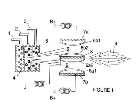](http://stanslegacy.com/uploads/images/gallery/2022-06/BPxw6tWgQ4t6K4fE-screenshot-from-2022-06-25-16-06-25.png) | [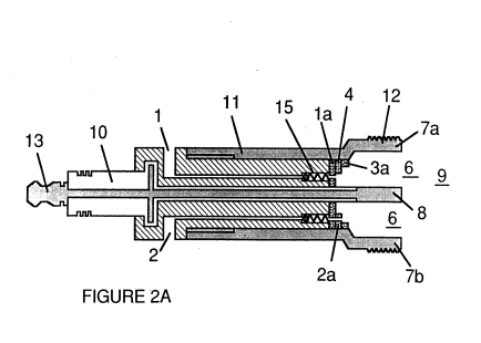](http://stanslegacy.com/uploads/images/gallery/2022-06/jbbljOtNrspzQXLs-screenshot-from-2022-06-25-16-06-31.png) | [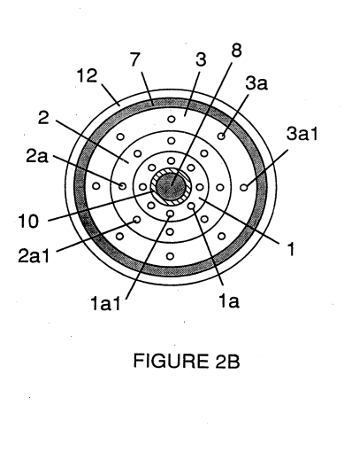](http://stanslegacy.com/uploads/images/gallery/2022-06/HCagrcMh2x9XfZlk-screenshot-from-2022-06-25-16-07-16.png) |
| [](http://stanslegacy.com/uploads/images/gallery/2022-06/BKlT18F8VbG4FkpB-screenshot-from-2022-06-25-16-07-47.png) | [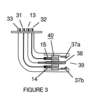](http://stanslegacy.com/uploads/images/gallery/2022-06/Xobr5XjZEJA3p3K0-screenshot-from-2022-06-25-16-06-42.png) | [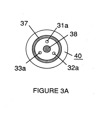](http://stanslegacy.com/uploads/images/gallery/2022-06/gI1VIukimfS7SEY0-screenshot-from-2022-06-25-16-07-31.png) |
| [](http://stanslegacy.com/uploads/images/gallery/2022-06/ulELezEpAcX50YUX-screenshot-from-2022-06-25-16-07-35.png) | [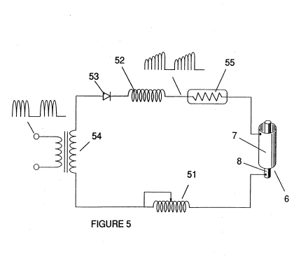](http://stanslegacy.com/uploads/images/gallery/2022-06/WKpYOR7WsjR4QmZF-screenshot-from-2022-06-25-16-06-47.png) | [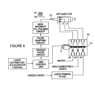](http://stanslegacy.com/uploads/images/gallery/2022-06/HCLF86fMdQMuxbsA-screenshot-from-2022-06-25-16-06-53.png) |
| [](http://stanslegacy.com/uploads/images/gallery/2022-06/jbbljOtNrspzQXLs-screenshot-from-2022-06-25-16-06-31.png) | [](http://stanslegacy.com/uploads/images/gallery/2022-06/HCagrcMh2x9XfZlk-screenshot-from-2022-06-25-16-07-16.png) | [](http://stanslegacy.com/uploads/images/gallery/2022-06/BKlT18F8VbG4FkpB-screenshot-from-2022-06-25-16-07-47.png) |
| [](http://stanslegacy.com/uploads/images/gallery/2022-06/gI1VIukimfS7SEY0-screenshot-from-2022-06-25-16-07-31.png) | [](http://stanslegacy.com/uploads/images/gallery/2022-06/Xobr5XjZEJA3p3K0-screenshot-from-2022-06-25-16-06-42.png) |
Pressure is an **important factor** in the maintenance of the reaction condition and causes the water mist/gas mixture to become intimately mixed, compressed, and destabilized to produce combustion when activated under resonance conditions of ignition.
In accordance with the aforementioned conversion process of my patent and application, when water is subjected to a resonance condition water molecules expand and distend; electrons are ejected from the water molecule and absorbed by ionized gases; and the water molecule, thus destabilized, breaks down into its elemental components of hydrogen (2H) and oxygen (0) in the combustion zone. The hydrogen atoms released from the molecule provide the fuel source in the mixture for combustion with oxygen. The present invention is an application of that process and is outlined in Table I: ##### TABLE I **[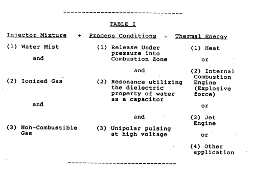](http://stanslegacy.com/uploads/images/gallery/2022-06/sBgjYBvthexRrAii-screenshot-from-2022-06-25-16-16-27.png)****Image Text:** Injector Mixture + Pr ndition = Thermal Energy (1) Water Mist (1) Release Under (1) Heat pressure into and Combustion Zone or and (2) Internal . : Combustion (2) Ionized Gas (2) Resonance utilizing Engine the dielectric (Explosive property of water force) as a capacitor and or and . (3) Jet Engine (3) Non-Combustible (3) Unipolar pulsing . Gas at high voltage or (4) Other application
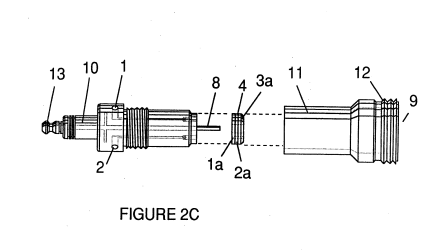
The process occurs as water mist and gases are injected under pressure into, and intimately mixed in the combustion zone and an electrically polarized zone. In the electrically polarized zone, the water mixture is subjected to a unipolar pulsed direct current voltage that is tuned to achieve resonance in accordance with the electrical, mass and other characteristics of the mixture as a dielectric in the environment of the combustion zone. The resonant frequency will vary according to injector configuration and depends upon the physical characteristics, such as mass and volume of water and gases in the zone. As my prior patents and application point out, the resonant condition in the capacitative circuit is determined by the dielectric properties of water: (1) as the dielectric in a capacitor formed by adjacent conductive surfaces and (2) as the water molecule itself is a polar dielectric material. At resonance, current Flow in the resonant electrical circuit will be minimized and voltage will peak. The injector system provides a pressurized fuel mixture for subjection to the resonant environment of the voltage ‘ combustion zone as the mixture is introduced to the zone. In a preferred embodiment, the injector includes concentrically nested serial orifices, one for each of three constituent elements of the fuel mixture. (It may be feasible to combine and process non-combustible and ionized gases in advance of the injector. In this event only two orifices are required, one for the water and the other for the combined gases.) The orifices disperse the water mist and gases under pressure into a conically shaped activation and combustion zone (or locus). Figure 1A shows a transverse cross-section of an injector in which supply lines for water 1 ionized gas 2 and non-combustible gas 3 feed into a distribution disk assembly 4 having concentrically nested orifices. The fuel mixture passes. through a mixing zone 5 and voltage zone 6 created by electrodes or conductive surfaces 7a and 7b (positive) and 8 (negative or ground). Electrical field lines as shown as 6al and 6a2 and 6bl and 6b2. Combustion (i.e., the oxidation of: hydrogen) occurs in the zone 9. Ignition of the hydrogen can be primed by a spark or may occur spontaneously as a result of the exceptionally high volatility of hydrogen. and its presence in a high voltage field. Although a differentiation of the mixing zone, the voltage zone and the combustion zone is made in explaining the invention, that differentiation relates to events or conditions in a process continuum, and ‘as is evident from Figure 1, the zones are not physically discrete. In the zone(s), there is produced an "excited" Mixture of vaporized water mist, ionized gases and other non-combustible gases all of which have been instantaneously released from under high pressure. Simultaneously, the released mixture is exposed to a pulsed voltage in the zone/ locus at a frequency corresponding to electrical resonance. Under these conditions, outer shell electrons of atoms in the water molecule are destabilized and molecular time share is interrupted. Thus, the gas mixture in the injector zone is subjected to physical, electrical and chemical interactive forces which cause a breakdown of the atomic bonding forces of the water molecule. Process parameters are determined based on the size of a particular injector. In an injector sized appropriately for use to provide a fuel mixture to a conventional cylinder in a passenger vehicle automobile engine, the injector may resemble a conventional spark plug. In such an injector, the water orifice is .10 to .15 inch in diameter; the ionized gas orifice is -15 to -20 inch in diameter; and the non-combustible gas orifice is .20 to .25 inch in diameter. In such a configuration, the serial orifices increase in size from the innermost orifice, as appropriate to a concentric configuration. As noted above, the introduction of the fuel components is desirably maintained at a constant rate; maintenance of a back pressure of about 125 pounds per square inch for each of the three fuel gas constituents appears satisfactorily useful for a “spark-plug\* injector. In the Pressurized environment of the injector, spring loaded one-way check valves in each supply line,’ such as 14 and 15, maintain pressure during pulse off times. The voltage zone 6 surrounds the pressurized fuel mixture and. provides an electrically charged environment of pulsed direct current in the range from about 500 to 20,000 and more volts at a frequency tuned into the resonant characteristic of the mixture. This frequency will typically lie within the range of from about 20 KHz to about 50 KHz, dependent, as noted above, on the mass flow of the mixture from the injector and the dielectric property of the mixture. In a, spark-plug sized injector, the voltage zone will typically extend longitudinally about -25 to 1.0 inch to permit sufficient dwell time of the water mist and gas mixture between the conductive sufaces 7 and 8 that form a Capacitor so that resonance occurs at a high voltage pulsed frequency and combustion is triggered. In the zone, an energy wave is formed related to the resonant pulse frequency. The wave continues to pulse through the flame in the combustion zone. The thermal energy produced is released as heat energy. Ina confined zone such as a piston/cylinder engine, gas detonation under resonant conditions produces explosive physical power. In the voltage zone, the time share ratio of the hydrogen and oxygen atoms comprising the individual water molecules in the water mist is upset in accordance with the process explained in my aforementioned patent no. 4,936,961 and application serial no. 07/460,859. To wit, the water molecule which is itself a polar structure, is distended or distorted in shape by being subjected to the polar electric field in the voltage zone. The resonant condition induced in the molecule by the unipolar pulses upsets the molecular bonding of shell electrons such that the water molecule, at resonance, breaks apart into its constituent atoms. In the voltage zone, the water (H20) molecules are excited into an ionized state; and the pre-ionized gas component of the fuel mixture captures the electrons released from the “water molecule. In this manner at the resonant condition, the water molecule is destabilized and the constituent atomic elements of the molecule, 2H and O, are released; and the released hydrogen atoms are available for combustion. The non-combustible gases in the fuel mixture reduce the burn rate of hydrogen to that of a hydrocarbon fuel such as gasoline -or kerosene from its normal burn rate (which is approximately 2.5 times that of gasoline). Hence the presence of non-combustible gases in the fuel mixture moderates energy release and modulate the rate at which the free hydrogen and oxygen molecules combine in the combustion process. The conversion process does not spontaneously occur and the condition in the zone must be carefully fine tuned to achieve an optimum input flow rate for water and the gases corresponding to the maintenance of a resonant condition. The input water mist and gases may likewise be injected into the zone in a physically pulsed \[on/off\] manner corresponding to the resonance achieved. In an internal combustion engine, the resonance of the electrical circuit and the physical pulsing of the input mixture may be required to be related to the combustion cycle of the reciprocating engine. In this regard, one or two conventional spark plugs may require a spark cycle tuned in correspondence to the ‘conversion cycle resonance so that combustion of the mixture will occur. Thus, the input flow, conversion rate and combustion rate are interrelated and optimally should each be tuned in accordance with the circuit resonance at which conversion occurs. The injection system of the present invention is suited to retrofit applications in conventionally fueled gasoline and diesel internal combustion engines and conventionally fueled jet aircraft engines. ##### ##### EXAMPLE 1 Figures 2A, 2B and 2C illustrate a type of injector useful, inter alia as a fuel source for a conventional internal combustion engine. In the cross-section of Figure 2A, reference numerals corresponding to identifying numerals used in Figure 1 show a supply line for water l leading to first distribution disc la and supply line for ionized gas 2, leading to second distribution disc 2a. In the cross section, the supply line for non-combustible gas 3 leading to distribution disc 3a is not illustrated, however, its location as a third line should be self-evident. The three discs comprise distribution disc assembly 4. The supply lines are formed in an electrically insulating body 10 surrounded by electrically conductive sheath/housing 11 having a threaded end segment 12.| [](http://stanslegacy.com/uploads/images/gallery/2022-06/jbbljOtNrspzQXLs-screenshot-from-2022-06-25-16-06-31.png) | [](http://stanslegacy.com/uploads/images/gallery/2022-06/HCagrcMh2x9XfZlk-screenshot-from-2022-06-25-16-07-16.png) | [](http://stanslegacy.com/uploads/images/gallery/2022-06/gWsvHKxaNzmtynhm-image-1656188554549.png) |
Fuel distribution and management systems useful with the injector of this application are described in my co-pending applications for patent, PCT/US90/6513 and PCT/US90/6407
A distribution block for the assembly is shown in Figure 6. In Figure 6 the distribution block pulses and synchronizes the input of the fuel components in sequence with the electrical pulsing circuit. The fuel components are injected into the injector ports in synchronization with the resonant frequency to enhance the energy wave pulse extending from the voltage zone through the flame. In the configuration of Figure 6, the electrical system is interrelated to distribution block 60, gate valve 61 and separate passageways 62, 63, and 64 for fuel components. The distributor produces a trigger pulse which activates a pulse shaping circuit that forms a pulse having a width and amplitude determined by resonance of the mixture and establishes a dwell time for the mixture in the zone to produce combustion. As in my referenced application regarding control and management and distribution systems for a hydrogen containing fuel gas produced from water, the production of hydrogen gas is related to pulse frequency on/off time. In the system shown in Figure 6, the distributor block pulses the fluid media introduced to the injector in relationship to the resonant pulse frequency of the circuit and to the operational on/off gate pulse frequency. In this Manner the rate of water conversion (i.e., the rate of fuel production by the injector) can be regulated and the pattern of resonance in the flame controlled. #### What is claimed is: 1\. The improved method of converting water into a hydrogen containing fuel comprising: > providing a mist of water in a defined zone determined by conductive members, the surfaces: of which define the opposite plates of a capacitive element in a resonant circuit, and > > subjecting the water mist in the zone to a unipolar pulsing electrical signal, such that resonance of the circuit is achieved, whereby hydrogen is disassociated from water molecules in the zone as a gas. 2\. The method of claim 1 in which the resonant circuit is an electrical circuit including an inductive member 3\. The method of Claim 2 in which the inductive member is in series relationship with the capacitive element. 4\. The method of Claim 1 in which non-combustible gases are injected with water into the zone. 5\. The method of Claim 1 in which ionized gases are injected with water into the zone. 6\. The method of Claim 5 in which the ionized gases are subjected to excitation by photons. 7\. The method of Claim 1 or Claim 2 or Claim 3 or Claim 4 or Claim 5 or Claim 6 including the oxidation of the hydrogen gas released to produce thermal energy. 8\. The method of Claim 1 or Claim 2 or Claim 3 or Claim 4 or Claim 5 or Claim 6 including the oxidation of the hydrogen gas released to produce an explosive force of combustion. 9\. The method of Claim 1 or Claim 2 or Claim 3 or Claim 4 or Claim 5 or Claim 6 in which the media in the zone is subjected in the zone to physical pulsing corresponding to the resonance of the circuit. 10\. Apparatus useful in a method for the conversion of water into a hydrogen fuel including: > electrically conductive surfaces that form the opposite surfaces of an electrically capacitive element in a circuit; > > means for injecting water as.a fine mist into the zone defined by the electrically conductive surfaces; and > > means for achieving resonance in the circuit at a frequency determined substantially by the dielectric properties of the water in the zone, whereby hydrogen is disassociated from water molecules in the zone as a gas. 11\. Apparatus in accordance with Claim 10 including means for the injection of gases with water into the zone to produce a mixture and in which the resonant frequency is related to the dielectric properties of the mixture. 12\. Apparatus in accordance with Claim 10 or Claim ll including means for causing ignition of the hydrogen gas. 13\. Apparatus in accordance with Claim 10 or Claim 11 including further means for subjecting the media in the zone to physical pulsing.