Arduino / ESP32 Projects
- ESP32 - Complex Waveform Generator V2
- ESP32 - CWG Driver & Amplification
- ESP32 - Complex Waveform Generator V3
- 2 Arduino - Dual Channel - Triple AND Gate (Perfect Pulse Driver)
ESP32 - Complex Waveform Generator V2
Setting Up The App
ESP32 Complex Waveform Generator - Arrangement for WROOM-32 or WROVER-E (DevKit-C)
PARTS Required
- 1 - ESP32 (WROOM-32 or WROVER-32) with 16 exposed pins
- 1 - ESP32 Breakout Board or equivalent pin header block
- 7 - Rotary Encoders (i.e. KY-040 Rotary Encoder Module CYT1062)
- TODO: add >= 2 more for Elongation adjustments.
- 1 - +5VREG 1A Power Supply for ESP32 (i.e. ATX PowerSupply)
Installation Prerequisites
Install ESP Libraries in Arduino-IDE v2.0
ArduinoJson
ESP32Encoder
Step 1. Open Esp32Full.ino and set Wifi Credentials
// #### Change Me - Local Wifi Info ####
const char *SSID = "NETGEAR";
const char *PWD = "12345678";
Step 2. Configure free local LAN IP address
Check your Router for more information
// #### CHANGE ME ####
// Set your Static IP address to a free IP in your local network
IPAddress local_IP(192, 168, 1, 8);
// Set your Gateway IP address
IPAddress gateway(192, 168, 1, 1);

IPAddress subnet(255, 255, 255, 0);
IPAddress primaryDNS(8, 8, 8, 8);   //optional
IPAddress secondaryDNS(8, 8, 4, 4); //optional
Step 3. Configure ESP_HOST in Javascript File
Edit `./assets/espwavegen.js` and set the IP address used in Step 2 above.
TODO: Make configurable in the web interface
Save and close the file
Step 3. Upload The code in `Esp32Full.ino`
Paste the code into your Arduino-IDE and upload it to your ESP32
Installing the ESP32 Board in Arduino IDE
Step 4. Access the WebApp in your Web Browser
Open Web Browser
Open `index.html` in the `WebApp` directory below this file
- File -> Open -> Browse to WebApp/index.html -> Open
Interface is now displayed!
Step 5: Enjoy!!
Please post pics and videos of your waves, and let others know how achievable this is!
Need Amplification?
See: ESP32 - Complex Waveform Generator - Driver & Amplification
Additional Troubleshooting / Customization
Optional: Configure alternate Output Pins
- Output will be on Pins D2 and D4 by default
// #### Output Pins ####
int pinChannel1 = 2;
int pinChannel2 = 4;
Optional: Adjust Encoder Pins if needed
int pulseCount_EncoderPIN1 = 14;
int pulseCount_EncoderPIN2 = 13;
int pulseWidth_EncoderPIN1 = 35;
int pulseWidth_EncoderPIN2 = 34;
int pulseSpace_EncoderPIN1 = 19;
int pulseSpace_EncoderPIN2 = 18;
int gate_freq_EncoderPIN1 = 22;
int gate_freq_EncoderPIN2 = 23;

int pulseWidthModifier_EncoderPIN1 = 27;
int pulseWidthModifier_EncoderPIN2 = 26;
int pulseSpaceModifier_EncoderPIN1 = 5;
int pulseSpaceModifier_EncoderPIN2 = 32;
int gateModifier_EncoderPIN1 = 25;
int gateModifier_EncoderPIN2 = 33;
ESP C+ Code
Git Repo: https://bitbucket.org/cbake6807/esp32-complex-waveform-generator/src/master/
Troubleshooting:
View the Console Log for errors in your browser while clicking the app's sliders buttons etc..
Look in the Network tab for red errors. 404 or other. Sometimes the ESP may drop or reject the connection on the first attempt. Just refresh the browser once or twice and it should resolve.
Confirm the ESP is a connected host in your network and was given the IP you specified
https://www.wikihow.com/See-Who-Is-Connected-to-Your-Wireless-Network
Code notes if internet connectivity isn't an option. Also, encoder wiring connections for this particular setup (Notepad++ document file type). Chris Bake ESP32 notes.txt
Notepad++ download: Notepad++
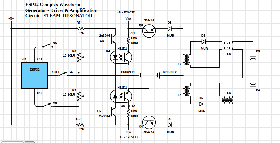
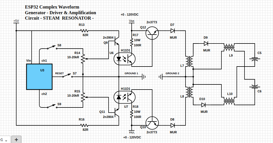
ESP32 - CWG Driver & Amplification
A dual channel, dual isolated power supply, pulse amplification for driving all VIC arrangements
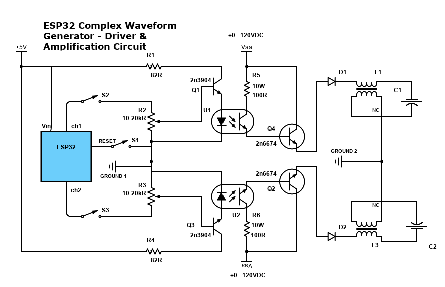
Arrangement favoring Particle Oscillation as an Energy Generator
Variation 2 - Ground Bonded / "Forced" Uni-polar Operation
ESP32 - Complex Waveform Generator V3
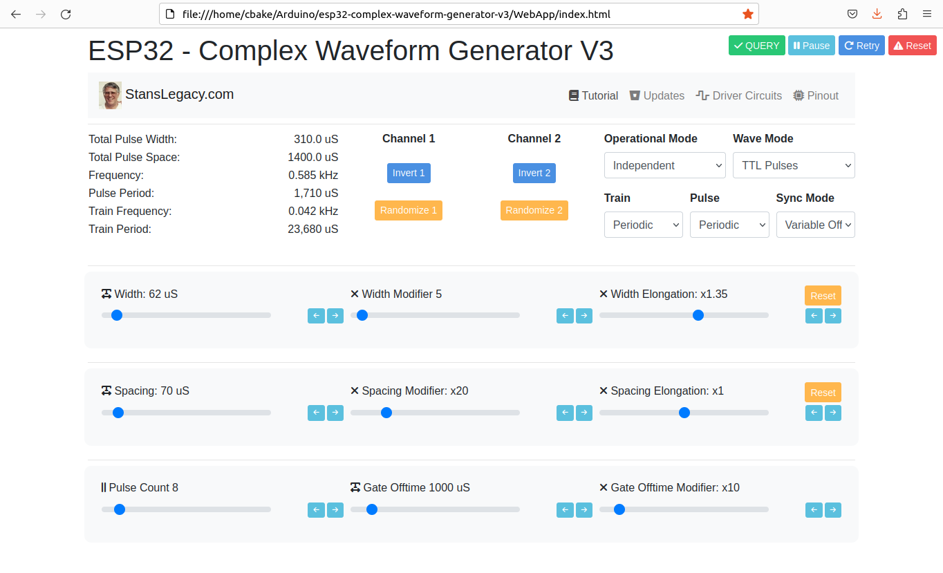
Installing and Using the ESP32 Complex Waveform Generator V3 Application
Screenshot of web interface
 |
 |
Prerequisites
To use this application, you need to have the Arduino IDE installed on your computer. You can download the Arduino IDE from the official website: https://www.arduino.cc/en/software
-
ESP32 Development Board: You'll need an ESP32 development board, such as the popular ESP32-DevKitC or ESP32-WROOM-32D. These boards typically come with Wi-Fi and Bluetooth capabilities and a variety of GPIO pins for interfacing with peripherals.
-
Rotary Encoders: To adjust the waveform parameters, you will need a total of 7 rotary encoders. You can use KY-040 rotary encoder modules or any other type of incremental rotary encoder with built-in push buttons. Ensure that the rotary encoders you choose have a CLK, DT, and SW (push button) pinout.
-
Breadboard and Jumper Wires: A breadboard and jumper wires are required to make the necessary connections between the ESP32 development board and the rotary encoders.
- Power Supply: You will need a power supply to power the ESP32 development board. This can be a USB power supply, a battery, or any other suitable power source that meets the board's voltage and current requirements, such an ATX Supply from a computer. 5VDC 1A minimum is recommended to prevent brownout conditions while interacting with a driver circuit.
-
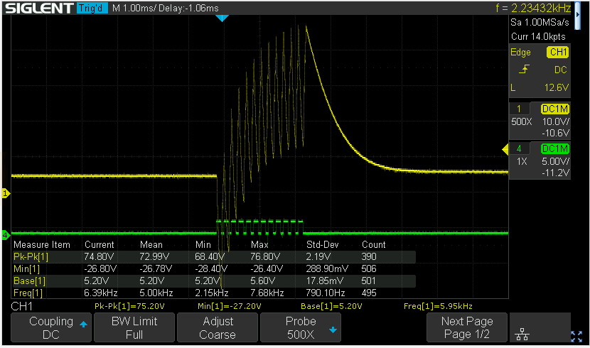
Oscilloscope (optional): To visualize the generated waveform, you can use an oscilloscope. Connect the output pins (channel1OutputPin and channel2OutputPin) from the ESP32 development board to the oscilloscope's input channels.
Installing required libraries
-
ArduinoJson: To install the ArduinoJson library, follow these steps: a. Open the Arduino IDE. b. Click on
Toolsin the menu bar, thenManage Libraries. c. In the Library Manager window, search for "ArduinoJson" in the search bar. d. Find "ArduinoJson by Benoit Blanchon" in the search results and click on theInstallbutton. -
ESP32Encoder: To install the ESP32Encoder library, follow these steps: a. Open the Arduino IDE. b. Click on
Toolsin the menu bar, thenManage Libraries. c. In the Library Manager window, search for "ESP32Encoder" in the search bar. d. Find "ESP32Encoder by Gil Mora" in the search results and click on theInstallbutton.
Uploading the Application
- Download the source code for the ESP32 Complex Waveform Generator V3 application or copy it to a new file in the Arduino IDE.
- Connect the ESP32 development board to your computer using a USB cable.
- In the Arduino IDE, select the appropriate board and port under
Tools>BoardandTools>Port. - Click on the
Uploadbutton (right-facing arrow icon) in the Arduino IDE to compile and upload the application to the ESP32 development board.
Hardware Setup
- Wire the rotary encoders and other components according to the pin assignments defined in the source code.
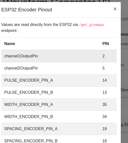
ESP32 Pin Encoder Connection Encoder Function 14 Pulse Encoder CLK Pulse count 13 Pulse Encoder DT Pulse count 35 Width Encoder CLK Pulse width 34 Width Encoder DT Pulse width 19 Spacing Encoder CLK Pulse spacing 18 Spacing Encoder DT Pulse spacing 23 Off-time Encoder CLK Off-time 22 Off-time Encoder DT Off-time 27 Width Mod Encoder CLK Width modifier 26 Width Mod Encoder DT Width modifier 15 Spacing Mod Encoder CLK Spacing modifier 32 Spacing Mod Encoder DT Spacing modifier 33 Off-time Mod Encoder CLK Off-time modifier 4 Off-time Mod Encoder DT Off-time modifier 2 Output Channel 1 Output waveform 5 Output Channel 2 Output waveform - Make sure the connections are secure and verify the CLK/DT pins for each encoder are wired correctly, and that each encoder turns in the correct direction relative to the respective parameter change.
Using the Application
- Power on the ESP32 development board.
- Use the rotary encoders to adjust the following parameters:
- Pulse count
- Pulse width
- Pulse spacing
- Off-time
- Width modifier
- Spacing modifier
- Off-time modifier
- The application will generate a complex waveform based on the adjusted parameters.
- Connect the output pins (channel1OutputPin and channel2OutputPin) to an oscilloscope to visualize the generated waveform.
- Open the WebApp/index.html page in a browser.
- Fine-tune the parameters using the rotary encoders to achieve the desired waveform shape and characteristics.
Next Steps For Utilization
- Build ESP32 CWG - VIC Driver circuit(s) - https://stanslegacy.com/books/chris-bake/page/esp32-cwg-driver-amplification
- Cell Construction - https://stanslegacy.com/books/ethan-crowder/page/resonant-cavity-related
Troubleshooting
- If the waveform does not match the expected output, verify the wiring connections and ensure the rotary encoders are functioning correctly.
- If the application does not upload to the ESP32 development board, double-check the board and port selection in the Arduino IDE.
- If the rotary encoders behave unexpectedly (e.g., adjusting one parameter affects another), check the CLK/DT pin assignments and wiring.
-
Click the PInout button to fetch the currently defined GPIO pins from the ESP32 directly and confirm they are wired correctly.

For further assistance or to report any issues, contact the application's support team or refer to the community forums.
2 Arduino - Dual Channel - Triple AND Gate (Perfect Pulse Driver)
By: Chris Bake
Arduino Code: https://bitbucket.org/cbake6807/dualtripleseq/src/master/
Parts List
- External Signal Generator: 0-5Vppk output.
- Power Supply: ATX is ideal, providing +5V REG and +12V REG.
- 2N7000 Signal MOSFETs: Quantity 6.
- IRFP460 or Similar Power N-channel MOSFET: Quantity 2.
- 56Ω 1/8W Resistors: Quantity 10.
- 100Ω 1/2W Resistors: Quantity 2.
- 4.7kΩ Resistors: Quantity 2.
- 2N3906 PNP General Purpose Transistor: Quantity 2 (can be substituted with any general PNP transistor).
- IR2110PB Gate Driver Chip 14-pin: Quantity 2.
- Arduino Nano (or similar): Quantity 2 (must support hardware PCNT).
- Rotary Encoder: Quantity 1.
Software Requirements
- Arduino IDE: Ensure it is installed and updated to the latest version.
- Encoder Library: Install via the Arduino Library Manager.
Arduino Setup
Pulse Counter Arduino
-
Upload Script
- Open the Arduino IDE.
- Connect the first Arduino (PulseCounter) to your PC.
- Open
PulseCounter.inofrom the provided file. - Upload the script to the Arduino.
-
Connect the Encoder
- Connect the encoder's VCC to the Arduino's 5V pin.
- Connect the encoder's GND to the Arduino's GND pin.
- Connect the encoder's CLK and DT pins to two digital pins on the Arduino D2 and D3.
- Connect the encoder's Button pin to D4.
-
Verify Encoder Output
- Open the Serial Monitor in the Arduino IDE.
- Rotate the encoder and check the output to confirm it is functioning correctly.
const int outputPin = 9;const int encoderPinA = 2;const int encoderPinB = 3;const int encoderSwitchPin = 4;const int disableSwitchPin = 6;
Adding a Pushbutton for Sync Mode Toggle
Parts Required
Hardware Connections
-
Connect the Pushbuttons
- NANO1 - D6 -> BUTTON -> GND
- NANO2 - D4 -> BUTTON -> GND
Summary of Connections
Sequencer Arduino
- Upload Script
- Disconnect the PulseCounter Arduino and connect the second Arduino (Sequencer) to your PC.
- Open
Sequencer.inofrom the provided file. - Upload the script to the Arduino.
Pin Mapping and Connections
Connecting the Two Arduinos
-
PulseCounter Arduino to Sequencer Arduino
- Signal Generator (+5Vppk max) →PulseCounter NANO1 - D5 (Input)
- Signal Generator (+5Vppk max)→Q2 First 2N7000 FET Gate
- Signal Generator (+5Vppk max)→Q7 First 2N7000 FET Gate (opposite branch)
- PulseCounter NANO1 - D9 (Output) → Sequencer NANO2 - D2 (Input)
- PulseCounter NANO1 - D9 (Output) → Q1 Second 2N7000 FET Gate
- PulseCounter NANO1 - D9 (Output) → Q6 Second 2N7000 FET Gate (opposite branch)
- Signal Generator (+5Vppk max) →PulseCounter NANO1 - D5 (Input)
-
Sequencer Arduino Outputs
- Sequencer NANO2- D9 (Output) → Input to Q4 - Third 2N7000 Gate.
- Sequencer NANO2 - D10 (Output) → Input to Q9 - Third 2N7000 Gate (opposite branch)
- Gate Enable/Disable Button
- Connect NANO1 - D6 -> BUTTON -> GND
- SyncMode / Offset Mode Button
- Connect NANO2 - D4 -> BUTTON -> GND
Note: The schematic shows the outputs merged due to limitations, but there should be dual outputs from the sequencer, D9 and D10, each connecting to a separate AND gate tree.
Gate Driver Chip Connections
IR2110PB Gate Driver Chip
-
Power Connections
- VCC (Pin 3) → +12V REG
- VSS (Pin 2, 10, 11, 15) → GND
- VDD (Pin 9) +5V REG
-
Input Connections
- LIN (Pin 12) → Arduino PWM pin (as per script)
-
Output Connections
- LO (Pin 1) → Gate of the IRFP460 MOSFET
-
Bootstrap Capacitor
- Connect a 22µF and a 100nF capacitor near VDD (Pin 9) and Ground.
- No Connection
- Pin 6, 7 - NC
-
Noise Filtering
- R2: Connect a 10Ω resistor between LO and the gate of the MOSFET.
- D2: Place a 1N4001 diode in parallel with the Resistor R2 in reverse direction for added noise filtering and protection.
Schematic Overview
Refer to the schematic image to visualize these connections. The IR2110PB gate driver chips control the IRFP460 MOSFETs, enabling high-power switching of the VIC (Voltage Intensifier Circuit) primaries.
Additional Notes
- Resistor Tolerances: The resistors can have a large tolerance. The 56Ω value is selected to preserve signal clarity. Any value ≤220Ω should be acceptable.
- Merged Outputs: The Arduino Channel Sequencer has 2 outputs shown merged due to Scheme-It limitations.