# Arduino / ESP32 Projects

# ESP32 - Complex Waveform Generator [LEGACY]

### Setting Up The App

##### Modify ESP C+ Code to configure local network settings

1. 1. Determine your local network's Subnet range (It should be one of these: 10.0.0.0/8, 192.168.0.0/16, or 172.xxx.xxx.xxx) 
        1. See: [https://www.businessinsider.com/how-to-find-ip-address-of-router](https://www.businessinsider.com/how-to-find-ip-address-of-router)
        2. Write down the address of your Gateway (your Router's IP address)
    2. Find a free DHCP issued internal IP address on your local network (Guess an IP not in use by picking a number between 100 and 255 for the very last position in your subnet: 192.168.1.xxx)
    3. Find your WIFI SSID and Password 
        1. SSID = The name of your Wifi Connection as your Phone or PC would see it on the network connection browser
        2. Password = Your Wifi Password
    4. Configure the IP, Gateway and your Wifi SSID &amp; credentials into the ESP code below 
        1. Preview Of areas to change in code below:
            
            ```C++
            // #### Change Me ####
            const char *SSID = "NETGEAR";
            const char *PWD = "12345678";
            
            // Don't Change Me
            const char *ASSET_HOST = "https://wavegenjs.s3.amazonaws.com";
            
            // Web server running on port 80
            WebServer server(80);
            
            // #### CHANGE ME ####
            // Set your Static IP address
            IPAddress local_IP(192, 168, 1, 8);
            // Set your Gateway IP address
            IPAddress gateway(192, 168, 1, 1);
            
            ```
    5. Copy the full script (down below) and paste it into your Arduino IDE 
        1. See: [https://randomnerdtutorials.com/how-to-install-esp8266-board-arduino-ide/](https://randomnerdtutorials.com/how-to-install-esp8266-board-arduino-ide/)
    6. Compile and Upload the code to the ESP32 
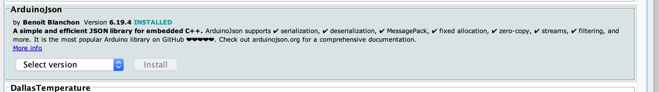
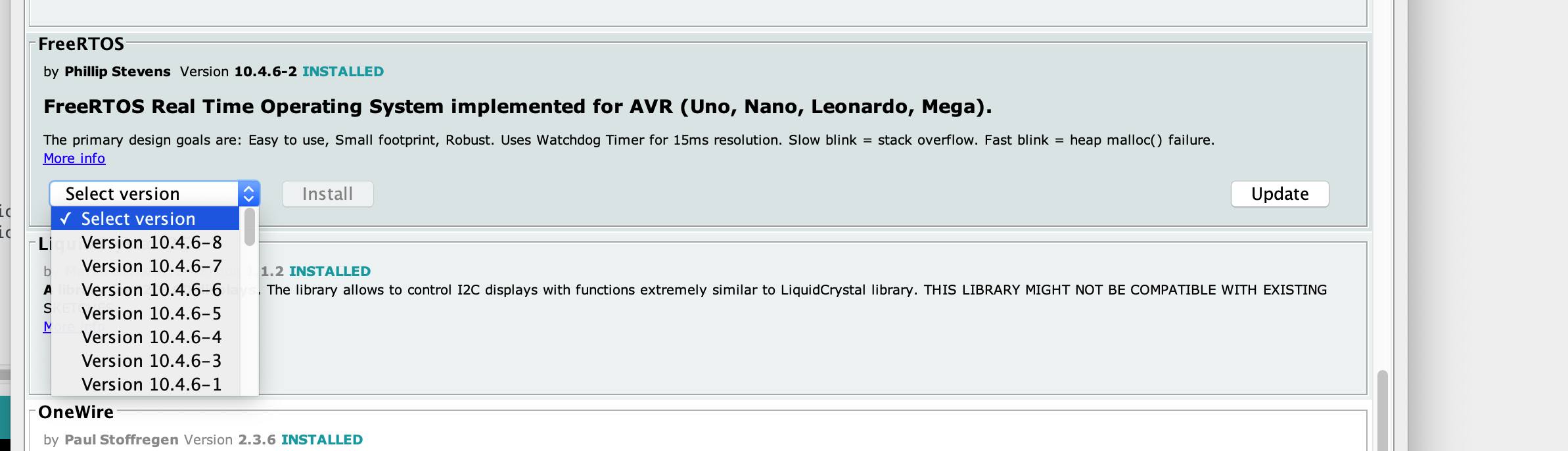
        1. Install required libraries (FreeRTOS, ArduinoJSON, Wifi, and WebServer.) 
            1. See: [https://docs.arduino.cc/software/ide-v1/tutorials/installing-libraries](https://docs.arduino.cc/software/ide-v1/tutorials/installing-libraries)
            2. [![298171574_5523327307690078_4273704313364637631_n.jpg](http://stanslegacy.com/uploads/images/gallery/2022-08/scaled-1680-/dm3BHay59TS8NGay-298171574-5523327307690078-4273704313364637631-n.jpg)](http://stanslegacy.com/uploads/images/gallery/2022-08/dm3BHay59TS8NGay-298171574-5523327307690078-4273704313364637631-n.jpg)
            3. [![298253535_5523321941023948_4638314484689292979_n.jpg](http://stanslegacy.com/uploads/images/gallery/2022-08/scaled-1680-/SCMvDM6ZTF2gTCWJ-298253535-5523321941023948-4638314484689292979-n.jpg)](http://stanslegacy.com/uploads/images/gallery/2022-08/SCMvDM6ZTF2gTCWJ-298253535-5523321941023948-4638314484689292979-n.jpg)
        2. Observe the Serial Monitor Log output from the Arduino IDE
        3. Confirm network connectivity was established with your router.
    7. Connect 2 separate Oscilloscope probes to pins "0" and "2" to ground, on your ESP.
    8. Open a web browser on a computer connected to the same internal network as the ESP was given 
        1. Go to the ESP's given IP Address: [http://192.168.1.8](http://192.168.1.8)
    9. Enjoy! (if it works)
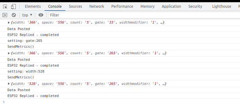
##### Troubleshooting:

View the Console Log for errors in your browser while clicking the app's sliders buttons etc..

[![Screenshot from 2022-08-06 13-24-55.png](http://stanslegacy.com/uploads/images/gallery/2022-08/scaled-1680-/VUxhtVg24Ps11Wlw-screenshot-from-2022-08-06-13-24-55.png)](http://stanslegacy.com/uploads/images/gallery/2022-08/VUxhtVg24Ps11Wlw-screenshot-from-2022-08-06-13-24-55.png)

<p class="callout info">[https://www.browserstack.com/guide/inspect-element-in-chrome#:~:text=One%20of%20the%20easiest%20ways,%2C%20Sources%2C%20and%20other%20tools](https://www.browserstack.com/guide/inspect-element-in-chrome#:~:text=One%20of%20the%20easiest%20ways,%2C%20Sources%2C%20and%20other%20tools).</p>

Confirm the ESP is a connected host in your network and was given the IP you specified

<p class="callout info">[https://www.wikihow.com/See-Who-Is-Connected-to-Your-Wireless-Network](https://www.wikihow.com/See-Who-Is-Connected-to-Your-Wireless-Network)</p>

#### ESP C+ Code

<details id="bkmrk-expand%23include-%3Cardu"><summary>Expand</summary>

```C++
#include <Arduino.h>
#include <WiFi.h>
#include <WebServer.h>
#include <ArduinoJson.h>
#include <FreeRTOS.h>

TaskHandle_t pulseTaskHandle;

// #### Change Me ####
const char *SSID = "NETGEAR";
const char *PWD = "12345678";

// Don't Change Me
//const char *ASSET_HOST = "https://wavegenjs.s3.amazonaws.com";
const char *ASSET_HOST = "http://192.168.1.2";

// Web server running on port 80
WebServer server(80);

// #### CHANGE ME ####
// Set your Static IP addres
IPAddress local_IP(192, 168, 1, 8);
// Set your Gateway IP address
IPAddress gateway(192, 168, 1, 1);

IPAddress subnet(255, 255, 255, 0);
IPAddress primaryDNS(8, 8, 8, 8);   //optional
IPAddress secondaryDNS(8, 8, 4, 4); //optional

// JSON data buffer
StaticJsonDocument<500> jsonDocument;
char buffer[500];

// env variable
float width = 150;
float space = 150;
float width1 = 0;
float space1 = 0;
float widthelongationmodifier = 1;
float spaceelongationmodifier = 1;
float gate = 1;
int count = 5;
int enablegate = 1;
int channels = 2;
int reference1 = LOW;
int reference2 = HIGH;
int enablealternate = 0;
int invertOne = 0;
int invertTwo = 0;
int ch1lastState = LOW;
int ch2lastState = LOW;

void connectToWiFi() {
  Serial.print("Connecting to ");
  Serial.println(SSID);
  // Configures static IP address
  if (!WiFi.config(local_IP, gateway, subnet, primaryDNS, secondaryDNS)) {
    Serial.println("STA Failed to configure");
  }
  WiFi.begin(SSID, PWD);
  while (WiFi.status() != WL_CONNECTED) {
    Serial.print(".");
    delay(500);
  }
  Serial.print("Connected. IP: ");
  Serial.println(WiFi.localIP());
}

void setup_routing() {
  server.enableCORS();
  server.on("/metrics", getMetrics);
  server.on("/set", HTTP_POST, handlePost);
  server.on("/", getIndex);
  server.begin();
}

void create_json(float width, float space, float count, float gate, float enablegate, float channels, float widthelongationmodifier, float spaceelongationmodifier, float enablealternate, int invertOne, int invertTwo) {
  jsonDocument.clear();
  jsonDocument["width"] = width;
  jsonDocument["space"] = space;
  jsonDocument["widthelongationmodifier"] = widthelongationmodifier;
  jsonDocument["spaceelongationmodifier"] = spaceelongationmodifier;
  jsonDocument["count"] = count;
  jsonDocument["gate"] = gate;
  jsonDocument["enablegate"] = enablegate;
  jsonDocument["channels"] = channels;
  jsonDocument["enablealternate"] = enablealternate;
  jsonDocument["invertOne"] = invertOne;
  jsonDocument["invertTwo"] = invertTwo;
  serializeJson(jsonDocument, buffer);
}

String getHtml() {
  String ptr = " <html>\n";
  ptr +="<head><meta name=\"viewport\" content=\"width=device-width, initial-scale=1.0, user-scalable=no\">\n";
  ptr +="<title>ESP32 Complex Waveform Generator</title>\n";
  ptr +="<script src=\"https://code.jquery.com/jquery-3.6.0.min.js\" integrity=\"sha256-/xUj+3OJU5yExlq6GSYGSHk7tPXikynS7ogEvDej/m4=\" crossorigin=\"anonymous\"></script>";
  ptr +="<link href=\"https://cdn.jsdelivr.net/npm/bootstrap@5.2.0/dist/css/bootstrap.min.css\" rel=\"stylesheet\" crossorigin=\"anonymous\"><script src=\"https://cdn.jsdelivr.net/npm/bootstrap@5.2.0/dist/js/bootstrap.bundle.min.js\" crossorigin=\"anonymous\"></script>";
  ptr +="<script src=\"https://code.highcharts.com/highcharts.js\"></script>";
  
  ptr +="<link href=\"";
  ptr += ASSET_HOST;
  ptr += "/espwavegen.css\" rel=\"stylesheet\"><script src=\"";
  ptr += ASSET_HOST;
  ptr += "/espwavegen.js\"></script>";
  ptr +="</head><body><div id=\"mainBody\"></div><div id=\"pulseChart\"></div><div id=\"widthChart\"></div></body></html>\n";
  return ptr;
}

void getIndex() {
  server.send(200, "text/html", getHtml()); 
}

void getMetrics() {
  create_json(width, space, count, gate, enablegate, channels, widthelongationmodifier, spaceelongationmodifier, enablealternate, invertOne, invertTwo);
  server.send(200, "application/json", buffer);
}

void handlePost() {
  if (server.hasArg("plain") == false) {
      Serial.println("no plain mode");
  }
  String body = server.arg("plain");
  deserializeJson(jsonDocument, body);
  width = jsonDocument["widthtotal"];
  space = jsonDocument["spacetotal"];
  widthelongationmodifier = jsonDocument["widthelongationmodifier"];
  spaceelongationmodifier = jsonDocument["spaceelongationmodifier"];
  count = jsonDocument["count"];
  gate = jsonDocument["gatetotal"];
  enablegate = jsonDocument["enablegate"];
  channels = jsonDocument["channels"];
  invertOne = jsonDocument["invertOne"];
  invertTwo = jsonDocument["invertTwo"];
  enablealternate = jsonDocument["enablealternate"];
  
  serializeJson(jsonDocument, buffer);
  server.send(200, "application/json", buffer);
}

void customDelay(long delayValue)
{
  long i = 0;
  int x = 0;
  for(i=0;i<delayValue;i++){
    for(x=0;x<80;x++){
      __asm__("nop\n\t");
    }
  }
}

void pulseClock(void * parameter) {
  Serial.println("restart loop");
  for(;;){ // ** Start of infinite loop **
     if(invertOne) {
      if(ch1lastState == LOW){
        ch1lastState = HIGH;
      } else {
        ch1lastState = LOW;
      }
    }
    if(invertTwo) {
      if(ch2lastState == LOW){
        ch2lastState = HIGH;
      } else {
        ch2lastState = LOW;
      }
    }
   
   width1 = width;
   space1 = space;
   for(int i=0; i<count; i++){    
      digitalWrite(2, ch2lastState);
      digitalWrite(0, ch1lastState);
      customDelay(width1);
//      ch1lastState = !ch1lastState;
//      ch2lastState = !ch2lastState;
      digitalWrite(2, !ch2lastState);
      digitalWrite(0, !ch1lastState);
      customDelay(space1);
      digitalWrite(2, ch2lastState);
      digitalWrite(0, ch1lastState);
      width1 = width1 * widthelongationmodifier;
      space1 = space1 * spaceelongationmodifier;
    }

    
    if(enablegate){
      if(enablealternate) {
        if(reference1 == HIGH){
          reference1 = LOW;
          reference2 = HIGH;
        } else {
          reference1 = HIGH;
          reference2 = LOW;
        }
    
        digitalWrite(2, reference1);
        digitalWrite(0, reference2);
      }      
      customDelay(gate);
    }
  }
  vTaskDelete(NULL);
}

void setup() {
  Serial.begin(115200);
  Serial.println("setup");
  connectToWiFi();
  setup_routing();

  pinMode(2, OUTPUT);
  pinMode(0, OUTPUT);
  pinMode(19, OUTPUT);
  pinMode(21, OUTPUT);
  digitalWrite(2, LOW);
  digitalWrite(0, LOW);
  digitalWrite(19, LOW);
  digitalWrite(21, LOW);

  xTaskCreatePinnedToCore(pulseClock,"Pulse Clock",10000,NULL,1,&pulseTaskHandle,1); 
}

void loop() {
  server.handleClient();
}
```

</details></body></html>

# ESP32 - Complex Waveform Generator V2

#### Setting Up The App

<p class="callout info">ESP32 Complex Waveform Generator - Arrangement for WROOM-32 or WROVER-E (DevKit-C)</p>

##### <iframe allowfullscreen="allowfullscreen" height="451" src="https://www.youtube.com/embed/AxDYTR773SM" style="width: 804px; height: 451px;" width="804"></iframe>


#####   
PARTS Required

- 1 - ESP32 (WROOM-32 or WROVER-32) with 16 exposed pins
- 1 - ESP32 Breakout Board or equivalent pin header block
- 7 - Rotary Encoders (i.e. KY-040 Rotary Encoder Module CYT1062) 
    - TODO: add &gt;= 2 more for Elongation adjustments.
- 1 - +5VREG 1A Power Supply for ESP32 (i.e. ATX PowerSupply)

##### Installation Prerequisites

Install ESP Libraries in Arduino-IDE v2.0

```MarkDown
ArduinoJson
ESP32Encoder
```

##### Step 1. Open Esp32Full.ino and set Wifi Credentials  


```
// #### Change Me - Local Wifi Info ####
const char *SSID = "NETGEAR";
const char *PWD = "12345678";

```

##### Step 2. Configure free local LAN IP address  


Check your Router for more information

```
// #### CHANGE ME ####
// Set your Static IP address to a free IP in your local network
IPAddress local_IP(192, 168, 1, 8);
// Set your Gateway IP address
IPAddress gateway(192, 168, 1, 1);

IPAddress subnet(255, 255, 255, 0);
IPAddress primaryDNS(8, 8, 8, 8);   //optional
IPAddress secondaryDNS(8, 8, 4, 4); //optional
```

##### <span style="text-decoration: line-through;">Step 3. Configure ESP\_HOST in Javascript File</span>  


<span style="text-decoration: line-through;">Edit `./assets/espwavegen.js` and set the IP address used in Step 2 above.</span>

<p class="callout warning"><span style="text-decoration: line-through;">TODO: Make configurable in the web interface</span>  
</p>

<span style="text-decoration: line-through;">Save and close the file</span>

##### Step 3. Upload The code in `Esp32Full.ino`  


Paste the code into your Arduino-IDE and upload it to your ESP32

<p class="callout info">[Installing the ESP32 Board in Arduino IDE](https://randomnerdtutorials.com/installing-the-esp32-board-in-arduino-ide-windows-instructions/ "Installing the ESP32 Board in Arduino IDE")</p>

##### Step 4. Access the WebApp in your Web Browser  


Open Web Browser  
Open `index.html` in the `WebApp` directory below this file

- File -&gt; Open -&gt; Browse to WebApp/index.html -&gt; Open

Interface is now displayed!

#### Step 5: Enjoy!!

Please post pics and videos of your waves, and let others know how achievable this is!

[![Screenshot from 2022-12-31 13-23-07.png](https://stanslegacy.com/uploads/images/gallery/2022-12/scaled-1680-/uaaVo1B7ToYrI4Lr-screenshot-from-2022-12-31-13-23-07.png)](https://stanslegacy.com/uploads/images/gallery/2022-12/uaaVo1B7ToYrI4Lr-screenshot-from-2022-12-31-13-23-07.png)

#### Need Amplification?

<p class="callout success">See: [ESP32 - Complex Waveform Generator - Driver &amp; Amplification](https://stanslegacy.com/books/chris-bake/page/esp32-cwg-driver-amplification)</p>

#### [![Esp32-Encoder-Setup (5).png](https://stanslegacy.com/uploads/images/gallery/2022-12/scaled-1680-/qqNXcCwadrtae9wk-esp32-encoder-setup-5.png)](https://stanslegacy.com/uploads/images/gallery/2022-12/qqNXcCwadrtae9wk-esp32-encoder-setup-5.png)

####   


####   
Additional Troubleshooting / Customization

#####   
Optional: Configure alternate Output Pins  


- Output will be on Pins D2 and D4 by default

```C++
// #### Output Pins ####
int pinChannel1 = 2;
int pinChannel2 = 4;

```

##### Optional: Adjust Encoder Pins if needed  


```C++
int pulseCount_EncoderPIN1 = 14;
int pulseCount_EncoderPIN2 = 13;
int pulseWidth_EncoderPIN1 = 35;
int pulseWidth_EncoderPIN2 = 34;
int pulseSpace_EncoderPIN1 = 19;
int pulseSpace_EncoderPIN2 = 18;
int gate_freq_EncoderPIN1 = 22;
int gate_freq_EncoderPIN2 = 23;

int pulseWidthModifier_EncoderPIN1 = 27;
int pulseWidthModifier_EncoderPIN2 = 26;
int pulseSpaceModifier_EncoderPIN1 = 5;
int pulseSpaceModifier_EncoderPIN2 = 32;
int gateModifier_EncoderPIN1 = 25;
int gateModifier_EncoderPIN2 = 33;
```

#### ESP C+ Code

<p class="callout info">Git Repo: [https://bitbucket.org/cbake6807/esp32-complex-waveform-generator/src/master/](https://bitbucket.org/cbake6807/esp32-complex-waveform-generator/src/master/)</p>

##### Troubleshooting:

View the Console Log for errors in your browser while clicking the app's sliders buttons etc..

Look in the Network tab for red errors. 404 or other. Sometimes the ESP may drop or reject the connection on the first attempt. Just refresh the browser once or twice and it should resolve.

[![Screenshot from 2022-08-06 13-24-55.png](http://stanslegacy.com/uploads/images/gallery/2022-08/scaled-1680-/VUxhtVg24Ps11Wlw-screenshot-from-2022-08-06-13-24-55.png)](http://stanslegacy.com/uploads/images/gallery/2022-08/VUxhtVg24Ps11Wlw-screenshot-from-2022-08-06-13-24-55.png)

<p class="callout info">[https://www.browserstack.com/guide/inspect-element-in-chrome#:~:text=One%20of%20the%20easiest%20ways,%2C%20Sources%2C%20and%20other%20tools](https://www.browserstack.com/guide/inspect-element-in-chrome#:~:text=One%20of%20the%20easiest%20ways,%2C%20Sources%2C%20and%20other%20tools).</p>

Confirm the ESP is a connected host in your network and was given the IP you specified

<p class="callout info">[https://www.wikihow.com/See-Who-Is-Connected-to-Your-Wireless-Network](https://www.wikihow.com/See-Who-Is-Connected-to-Your-Wireless-Network)</p>

``

Code notes if internet connectivity isn't an option. Also, encoder wiring connections for this particular setup (Notepad++ document file type). [Chris Bake ESP32 notes.txt](https://stanslegacy.com/attachments/116)

Notepad++ download: [Notepad++](https://stanslegacy.com/attachments/117)

# ESP32 - CWG Driver & Amplification

#### A dual channel, dual isolated power supply, pulse amplification for driving all VIC arrangements

[![schemeit-project(2).png](https://stanslegacy.com/uploads/images/gallery/2023-02/scaled-1680-/JcsTkR0DgHVFVMkD-schemeit-project2.png)](https://stanslegacy.com/uploads/images/gallery/2023-02/JcsTkR0DgHVFVMkD-schemeit-project2.png)

[![Esp32-Encoder-Setup (5).png](https://stanslegacy.com/uploads/images/gallery/2022-12/scaled-1680-/qqNXcCwadrtae9wk-esp32-encoder-setup-5.png)](https://stanslegacy.com/uploads/images/gallery/2022-12/qqNXcCwadrtae9wk-esp32-encoder-setup-5.png)

##### Arrangement favoring Particle Oscillation as an Energy Generator

[![Screenshot from 2022-12-24 20-09-21.png](https://stanslegacy.com/uploads/images/gallery/2022-12/scaled-1680-/bpPuUTGMyzm4dC6m-screenshot-from-2022-12-24-20-09-21.png)](https://stanslegacy.com/uploads/images/gallery/2022-12/bpPuUTGMyzm4dC6m-screenshot-from-2022-12-24-20-09-21.png)

##### Variation 2 - Ground Bonded / "Forced" Uni-polar Operation

[![Screenshot from 2022-12-24 20-09-13.png](https://stanslegacy.com/uploads/images/gallery/2022-12/scaled-1680-/ywzysAuQq2M7ZuHx-screenshot-from-2022-12-24-20-09-13.png)](https://stanslegacy.com/uploads/images/gallery/2022-12/ywzysAuQq2M7ZuHx-screenshot-from-2022-12-24-20-09-13.png)

# ESP32 - Complex Waveform Generator V3

#### Installing and Using the ESP32 Complex Waveform Generator V3 Application

Screenshot of web interface

<table border="1" id="bkmrk-" style="border-collapse: collapse; width: 136.049%; height: 506px;"><tbody><tr><td style="width: 50.0567%;">[![image-1683400232715.png](https://stanslegacy.com/uploads/images/gallery/2023-05/scaled-1680-/MX4zLcrWYrUJauHX-image-1683400232715.png)](https://stanslegacy.com/uploads/images/gallery/2023-05/MX4zLcrWYrUJauHX-image-1683400232715.png)</td><td style="width: 50.0567%;">[![342755495_606076878142350_7100434860017235921_n.png](https://stanslegacy.com/uploads/images/gallery/2023-05/scaled-1680-/G1uYZlR7805tiMpU-342755495-606076878142350-7100434860017235921-n.png)](https://stanslegacy.com/uploads/images/gallery/2023-05/G1uYZlR7805tiMpU-342755495-606076878142350-7100434860017235921-n.png)</td></tr></tbody></table>

### Prerequisites

To use this application, you need to have the Arduino IDE installed on your computer. You can download the Arduino IDE from the official website: [https://www.arduino.cc/en/software](https://www.arduino.cc/en/software)

1. **ESP32 Development Board**: You'll need an ESP32 development board, such as the popular ESP32-DevKitC or ESP32-WROOM-32D. These boards typically come with Wi-Fi and Bluetooth capabilities and a variety of GPIO pins for interfacing with peripherals.
2. **Rotary Encoders**: To adjust the waveform parameters, you will need a total of 7 rotary encoders. You can use KY-040 rotary encoder modules or any other type of incremental rotary encoder with built-in push buttons. Ensure that the rotary encoders you choose have a CLK, DT, and SW (push button) pinout.
3. **Breadboard and Jumper Wires**: A breadboard and jumper wires are required to make the necessary connections between the ESP32 development board and the rotary encoders.
4. **Power Supply**: You will need a power supply to power the ESP32 development board. This can be a USB power supply, a battery, or any other suitable power source that meets the board's voltage and current requirements, such an ATX Supply from a computer. 5VDC 1A minimum is recommended to prevent brownout conditions while interacting with a driver circuit.
5. **Oscilloscope (optional)**: To visualize the generated waveform, you can use an oscilloscope. Connect the output pins (channel1OutputPin and channel2OutputPin) from the ESP32 development board to the oscilloscope's input channels.

#### Installing required libraries

<div class="flex flex-grow flex-col gap-3" id="bkmrk-arduinojson%3A-to-inst"><div class="flex flex-grow flex-col gap-3"><div class="min-h-[20px] flex flex-col items-start gap-4 whitespace-pre-wrap break-words"><div class="markdown prose w-full break-words dark:prose-invert dark">1. **ArduinoJson**: To install the ArduinoJson library, follow these steps: a. Open the Arduino IDE. b. Click on `Tools` in the menu bar, then `Manage Libraries`. c. In the Library Manager window, search for "ArduinoJson" in the search bar. d. Find "ArduinoJson by Benoit Blanchon" in the search results and click on the `Install` button.
2. **ESP32Encoder**: To install the ESP32Encoder library, follow these steps: a. Open the Arduino IDE. b. Click on `Tools` in the menu bar, then `Manage Libraries`. c. In the Library Manager window, search for "ESP32Encoder" in the search bar. d. Find "ESP32Encoder by Gil Mora" in the search results and click on the `Install` button.

</div></div></div></div>#### Uploading the Application

<div class="flex flex-grow flex-col gap-3" id="bkmrk-download-the-source-"><div class="flex flex-grow flex-col gap-3"><div class="min-h-[20px] flex flex-col items-start gap-4 whitespace-pre-wrap break-words"><div class="markdown prose w-full break-words dark:prose-invert dark">1. Download the source code for the [ESP32 Complex Waveform Generator V3](https://bitbucket.org/cbake6807/esp32-complex-waveform-generator-v3/src/master/) application or copy it to a new file in the Arduino IDE.
2. Connect the ESP32 development board to your computer using a USB cable.
3. In the Arduino IDE, select the appropriate board and port under `Tools` &gt; `Board` and `Tools` &gt; `Port`.
4. Click on the `Upload` button (right-facing arrow icon) in the Arduino IDE to compile and upload the application to the ESP32 development board.

</div></div></div></div>#### Hardware Setup

<div class="flex flex-grow flex-col gap-3" id="bkmrk-wire-the-rotary-enco"><div class="flex flex-grow flex-col gap-3"><div class="min-h-[20px] flex flex-col items-start gap-4 whitespace-pre-wrap break-words"><div class="markdown prose w-full break-words dark:prose-invert dark">1. Wire the rotary encoders and other components according to the pin assignments defined in the source code. <table style="height: 498px; width: 100.057%;"><thead><tr><th style="width: 33.2698%;">ESP32 Pin</th><th style="width: 33.2698%;">Encoder Connection</th><th style="width: 33.2698%;">Encoder Function</th></tr></thead><tbody><tr><td style="width: 33.2698%;">14</td><td style="width: 33.2698%;">Pulse Encoder CLK</td><td style="width: 33.2698%;">Pulse count</td></tr><tr><td style="width: 33.2698%;">13</td><td style="width: 33.2698%;">Pulse Encoder DT</td><td style="width: 33.2698%;">Pulse count</td></tr><tr><td style="width: 33.2698%;">35</td><td style="width: 33.2698%;">Width Encoder CLK</td><td style="width: 33.2698%;">Pulse width</td></tr><tr><td style="width: 33.2698%;">34</td><td style="width: 33.2698%;">Width Encoder DT</td><td style="width: 33.2698%;">Pulse width</td></tr><tr><td style="width: 33.2698%;">19</td><td style="width: 33.2698%;">Spacing Encoder CLK</td><td style="width: 33.2698%;">Pulse spacing</td></tr><tr><td style="width: 33.2698%;">18</td><td style="width: 33.2698%;">Spacing Encoder DT</td><td style="width: 33.2698%;">Pulse spacing</td></tr><tr><td style="width: 33.2698%;">23</td><td style="width: 33.2698%;">Off-time Encoder CLK</td><td style="width: 33.2698%;">Off-time</td></tr><tr><td style="width: 33.2698%;">22</td><td style="width: 33.2698%;">Off-time Encoder DT</td><td style="width: 33.2698%;">Off-time</td></tr><tr><td style="width: 33.2698%;">27</td><td style="width: 33.2698%;">Width Mod Encoder CLK</td><td style="width: 33.2698%;">Width modifier</td></tr><tr><td style="width: 33.2698%;">26</td><td style="width: 33.2698%;">Width Mod Encoder DT</td><td style="width: 33.2698%;">Width modifier</td></tr><tr><td style="width: 33.2698%;">15</td><td style="width: 33.2698%;">Spacing Mod Encoder CLK</td><td style="width: 33.2698%;">Spacing modifier</td></tr><tr><td style="width: 33.2698%;">32</td><td style="width: 33.2698%;">Spacing Mod Encoder DT</td><td style="width: 33.2698%;">Spacing modifier</td></tr><tr><td style="width: 33.2698%;">33</td><td style="width: 33.2698%;">Off-time Mod Encoder CLK</td><td style="width: 33.2698%;">Off-time modifier</td></tr><tr><td style="width: 33.2698%;">4  
    </td><td style="width: 33.2698%;">Off-time Mod Encoder DT</td><td style="width: 33.2698%;">Off-time modifier</td></tr><tr><td style="width: 33.2698%;">2</td><td style="width: 33.2698%;">Output Channel 1</td><td style="width: 33.2698%;">Output waveform</td></tr><tr><td style="width: 33.2698%;">5</td><td style="width: 33.2698%;">Output Channel 2</td><td style="width: 33.2698%;">Output waveform</td></tr></tbody></table>
2. Make sure the connections are secure and verify the CLK/DT pins for each encoder are wired correctly, and that each encoder turns in the correct direction relative to the respective parameter change.

</div></div></div></div>#### Using the Application

<div class="flex flex-grow flex-col gap-3" id="bkmrk-power-on-the-esp32-d"><div class="flex flex-grow flex-col gap-3"><div class="flex flex-grow flex-col gap-3"><div class="min-h-[20px] flex flex-col items-start gap-4 whitespace-pre-wrap break-words"><div class="markdown prose w-full break-words dark:prose-invert dark">1. Power on the ESP32 development board.
2. Use the rotary encoders to adjust the following parameters: 
    - Pulse count
    - Pulse width
    - Pulse spacing
    - Off-time
    - Width modifier
    - Spacing modifier
    - Off-time modifier
3. The application will generate a complex waveform based on the adjusted parameters.
4. Connect the output pins (channel1OutputPin and channel2OutputPin) to an oscilloscope to visualize the generated waveform.
5. Open the WebApp/index.html page in a browser.
6. Fine-tune the parameters using the rotary encoders to achieve the desired waveform shape and characteristics.

</div></div></div></div></div>#### Next Steps For Utilization

<div class="flex flex-grow flex-col gap-3" id="bkmrk-build-esp32-cwg---vi"><div class="flex flex-grow flex-col gap-3"><div class="min-h-[20px] flex flex-col items-start gap-4 whitespace-pre-wrap break-words"><div class="markdown prose w-full break-words dark:prose-invert dark">- Build ESP32 CWG - VIC Driver circuit(s) - [https://stanslegacy.com/books/chris-bake/page/esp32-cwg-driver-amplification](https://stanslegacy.com/books/chris-bake/page/esp32-cwg-driver-amplification)
- Cell Construction - [https://stanslegacy.com/books/ethan-crowder/page/resonant-cavity-related](https://stanslegacy.com/books/ethan-crowder/page/resonant-cavity-related)

</div></div></div></div>#### Troubleshooting

<div class="flex flex-grow flex-col gap-3" id="bkmrk-if-the-waveform-does"><div class="flex flex-grow flex-col gap-3"><div class="min-h-[20px] flex flex-col items-start gap-4 whitespace-pre-wrap break-words"><div class="markdown prose w-full break-words dark:prose-invert dark">1. If the waveform does not match the expected output, verify the wiring connections and ensure the rotary encoders are functioning correctly.
2. If the application does not upload to the ESP32 development board, double-check the board and port selection in the Arduino IDE.
3. If the rotary encoders behave unexpectedly (e.g., adjusting one parameter affects another), check the CLK/DT pin assignments and wiring.
4. Click the PInout button to fetch the currently defined GPIO pins from the ESP32 directly and confirm they are wired correctly.
    
    [![image-1683400997931.png](https://stanslegacy.com/uploads/images/gallery/2023-05/scaled-1680-/0KZXcho6wJLP4Onh-image-1683400997931.png)](https://stanslegacy.com/uploads/images/gallery/2023-05/0KZXcho6wJLP4Onh-image-1683400997931.png)

</div></div></div></div>For further assistance or to report any issues, contact the application's support team or refer to the community forums.

# 2 Arduino - Dual Channel - Triple AND Gate (Perfect Pulse Driver)

By: Chris Bake

**Arduino Code**: [https://bitbucket.org/cbake6807/dualtripleseq/src/master/](https://bitbucket.org/cbake6807/dualtripleseq/src/master/)

#### Parts List

1. **External Signal Generator**: 0-5Vppk output.
2. **Power Supply**: ATX is ideal, providing +5V REG and +12V REG.
3. **2N7000 Signal MOSFETs**: Quantity 6.
4. **IRFP460 or Similar Power N-channel MOSFET**: Quantity 2.
5. **56Ω 1/8W Resistors**: Quantity 10.
6. **100Ω 1/2W Resistors**: Quantity 2.
7. **4.7kΩ Resistors**: Quantity 2.
8. **2N3906 PNP General Purpose Transistor**: Quantity 2 (can be substituted with any general PNP transistor).
9. **IR2110PB Gate Driver Chip 14-pin**: Quantity 2.
10. **Arduino Nano (or similar)**: Quantity 2 (must support hardware PCNT).
11. **Rotary Encoder**: Quantity 1.

#### Software Requirements

- **Arduino IDE**: Ensure it is installed and updated to the latest version.
- **Encoder Library**: Install via the Arduino Library Manager.

###   


### Arduino Setup

#### Pulse Counter Arduino

1. **Upload Script**
    
    
    - Open the Arduino IDE.
    - Connect the first Arduino (PulseCounter) to your PC.
    - Open `PulseCounter.ino` from the provided file.
    - Upload the script to the Arduino.
2. **Connect the Encoder**
    
    
    - Connect the encoder's VCC to the Arduino's 5V pin.
    - Connect the encoder's GND to the Arduino's GND pin.
    - Connect the encoder's CLK and DT pins to two digital pins on the Arduino D2 and D3.
    - Connect the encoder's Button pin to <span style="background-color: #fbeeb8;">D4</span>.
3. **Verify Encoder Output**
    
    
    - Open the Serial Monitor in the Arduino IDE.
    - Rotate the encoder and check the output to confirm it is functioning correctly.

> <div>const int outputPin = 9;</div><div>const int encoderPinA = 2;</div><div>const int encoderPinB = 3;</div><div>const int encoderSwitchPin = 4;</div><div>const int disableSwitchPin = 6;</div>

#### Adding a Pushbutton for Sync Mode Toggle

To add a pushbutton to the Sequencer Arduino for toggling the sync mode, follow these instructions:

##### Parts Required

- **Pushbutton**: Quantity 1
- **10kΩ Resistor**: Quantity 1
- **Connecting Wires**

##### Hardware Connections

1. **Connect the Pushbuttons**
    
    
    - NANO1 - <span style="background-color: #fbeeb8;">D6</span> -&gt; BUTTON -&gt; GND
    - NANO2 - <span style="background-color: #fbeeb8;">D4</span> -&gt; BUTTON -&gt; GND

<p class="callout info">Summary of Connections</p>

#### Sequencer Arduino

1. **Upload Script**
    - Disconnect the PulseCounter Arduino and connect the second Arduino (Sequencer) to your PC.
    - Open `Sequencer.ino` from the provided file.
    - Upload the script to the Arduino.

### Pin Mapping and Connections

#### Connecting the Two Arduinos

- **PulseCounter Arduino to Sequencer Arduino**
    
    
    - Signal Generator (+5Vppk max) →PulseCounter NANO1 - D5 (Input) 
        - Signal Generator (+5Vppk max)→Q2 **First** 2N7000 FET Gate
        - Signal Generator (+5Vppk max)→Q7 **First** 2N7000 FET Gate (opposite branch)
    - PulseCounter NANO1 - D9 (Output) → Sequencer NANO2 - D2 (Input) 
        - PulseCounter NANO1 - D9 (Output) → Q1 **Second** 2N7000 FET Gate
        - PulseCounter NANO1 - D9 (Output) → Q6 **Second** 2N7000 FET Gate (opposite branch)
- **Sequencer Arduino Outputs**
    
    
    - Sequencer NANO2- D9 (Output) → Input to Q4 - **Third** 2N7000 Gate.
    - Sequencer NANO2 - D10 (Output) → Input to Q9 - **Third** 2N7000 Gate (opposite branch)
- **Gate Enable/Disable Button**
    - Connect NANO1 - D6 -&gt; BUTTON -&gt; GND
- **SyncMode / Offset Mode Button**
    - Connect NANO2 - D4 -&gt; BUTTON -&gt; GND

<p class="callout danger">**Note:** The schematic shows the outputs merged due to limitations, but there should be dual outputs from the sequencer, D9 and D10, each connecting to a separate AND gate tree.</p>

- **Shared Connections**
    - Both Arduinos' GND pins should be connected together to ensure a common ground.

### Gate Driver Chip Connections

#### IR2110PB Gate Driver Chip

1. **Power Connections**
    
    
    - VCC (Pin 3) → +12V REG
    - VSS (Pin 2, 10, 11, 15) → GND
    - VDD (Pin 9) +5V REG
2. **Input Connections**
    
    
    - LIN (Pin 12) → Arduino PWM pin (as per script)
3. **Output Connections**
    
    
    - LO (Pin 1) → Gate of the IRFP460 MOSFET
4. **Bootstrap Capacitor**
    
    
    - Connect a 22µF and a 100nF capacitor near VDD (Pin 9) and Ground.
5. **No Connection**
    1. Pin 6, 7 - NC
6. **Noise Filtering**
    
    
    - R2: Connect a 10Ω resistor between LO and the gate of the MOSFET.
    - D2: Place a 1N4001 diode in parallel with the Resistor R2 in reverse direction for added noise filtering and protection.

### Schematic Overview

Refer to the schematic image to visualize these connections. The IR2110PB gate driver chips control the IRFP460 MOSFETs, enabling high-power switching of the VIC (Voltage Intensifier Circuit) primaries.

### Additional Notes

- **Resistor Tolerances**: The resistors can have a large tolerance. The 56Ω value is selected to preserve signal clarity. Any value ≤220Ω should be acceptable.
- **Merged Outputs**: The Arduino Channel Sequencer has 2 outputs shown merged due to Scheme-It limitations.

[![image-1719630807457.png](https://stanslegacy.com/uploads/images/gallery/2024-06/scaled-1680-/3tIVYmfAyboOM3bo-image-1719630807457.png)](https://stanslegacy.com/uploads/images/gallery/2024-06/3tIVYmfAyboOM3bo-image-1719630807457.png)