# Chris Bake
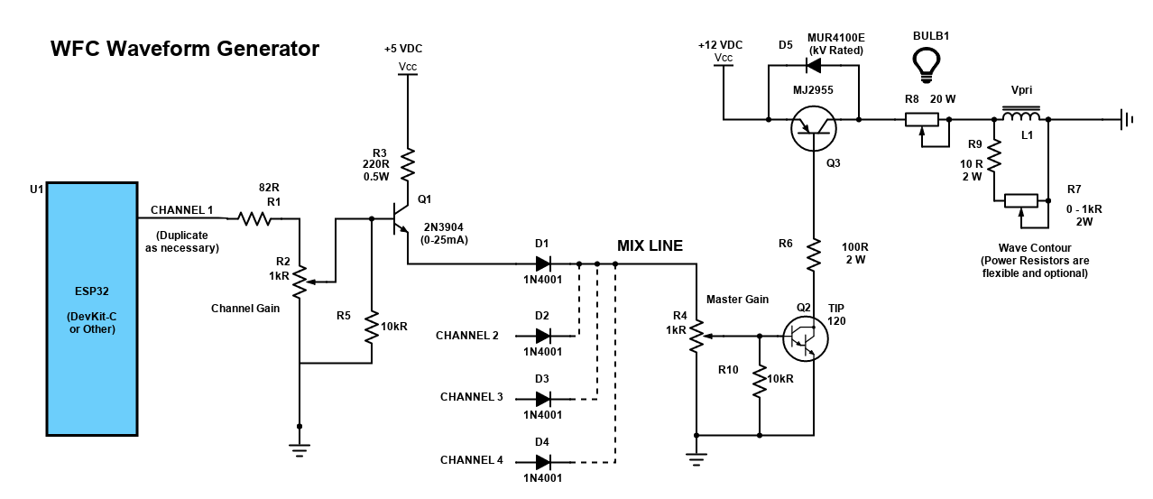
# Web Based VIC
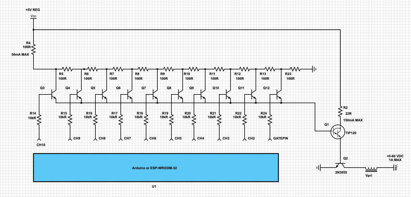
# 1-10 Channel Analog Amplitude Modulator
[](http://stanslegacy.com/uploads/images/gallery/2022-06/sG8Y1dqkrzQO4OI3-265079631-3195161367363934-1991161274925674298-n.png)
[](http://stanslegacy.com/uploads/images/gallery/2022-06/6c0obEebyYYRJojJ-wfc-waveform-generator-1.png)
# ESP32 Rest API, Pulse Clock & VIC Configurator
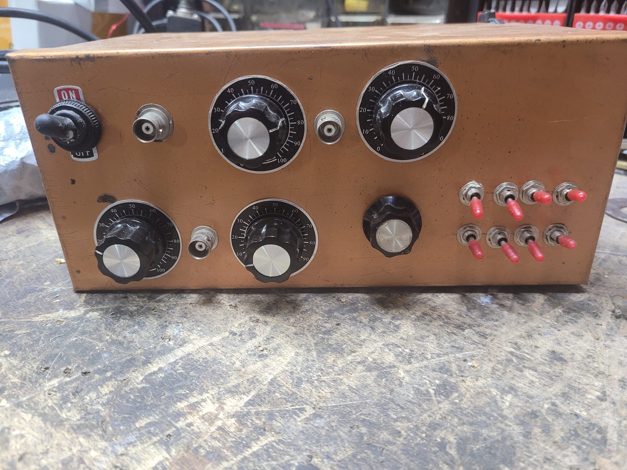
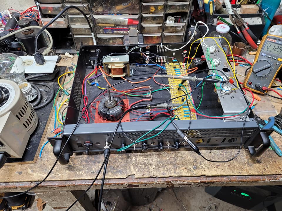
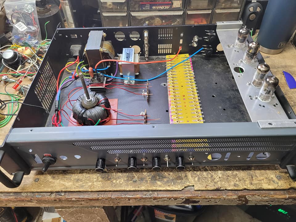
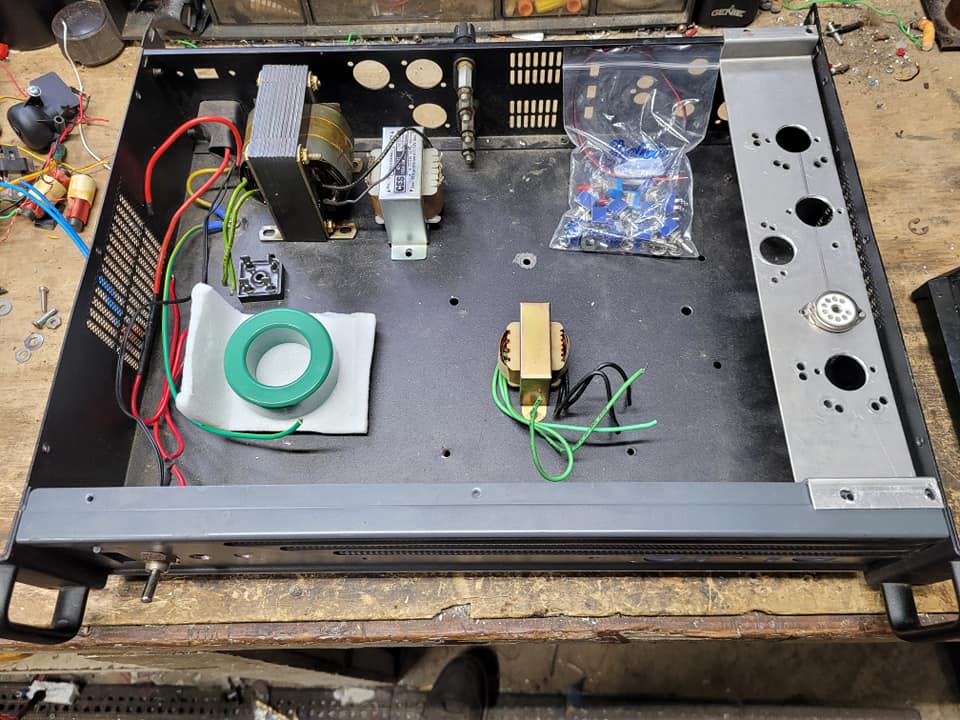
# Phase Selectable VIC
Utilizing DPDT toggle switches to allow inline phase inversion of each VIC component allow significant selectivity in operational configurations.
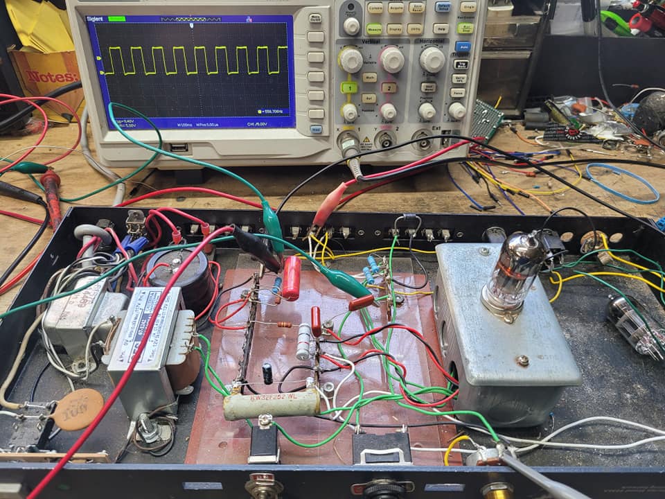
450VDC push-pull EL34 vacuum tube driven VIC 4:1 stepdown ferromagnetic core
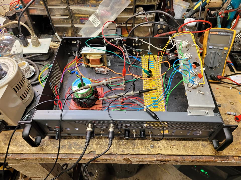
Earlier version of above, but with an added DPDT relay driven by a 3rd signal input and darlington driver, attempting the Crossover Voltage Switching utilized in the Steam Resonator.
With the monster transformer in there, I would get a very strange buildup of electrostatic vibrations on the metal chassis. No vibrations were felt on the plastic of the meter panels, but everywhere on the metal parts.
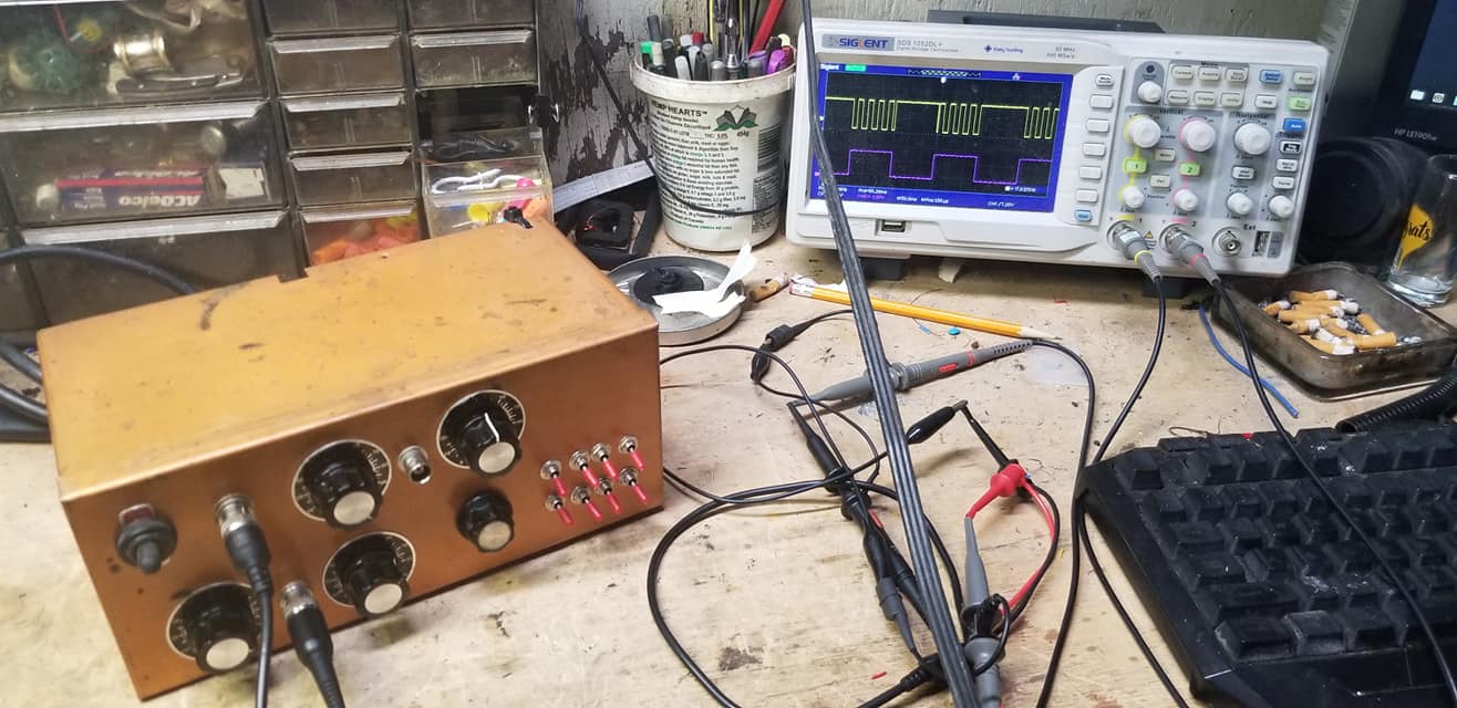
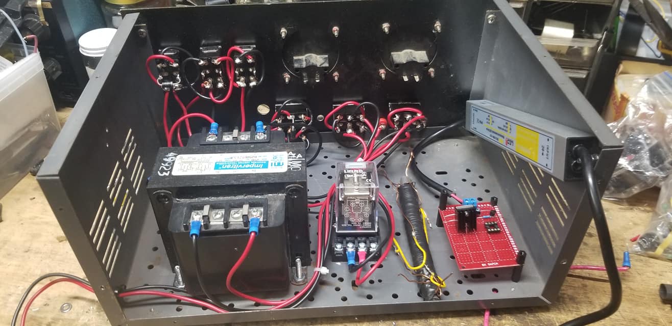
# CrayonXA (My First 9XA)
Learning transistors, power supplies, 555 timers, Schmidt Triggers, AND gates, darlington transistors and optocouplers all in one shot. It still amazes me this ever worked :)
The circuit for this design originated from [Max Miller's 9XA](http://irondmax.com/pdf/ProjectIcarus.pdf) (drawn in crayon)
| [](http://stanslegacy.com/uploads/images/gallery/2022-06/SOVr9QE15JbSjfUb-240662288-4705169929505824-3723763710195030686-n.jpg) | [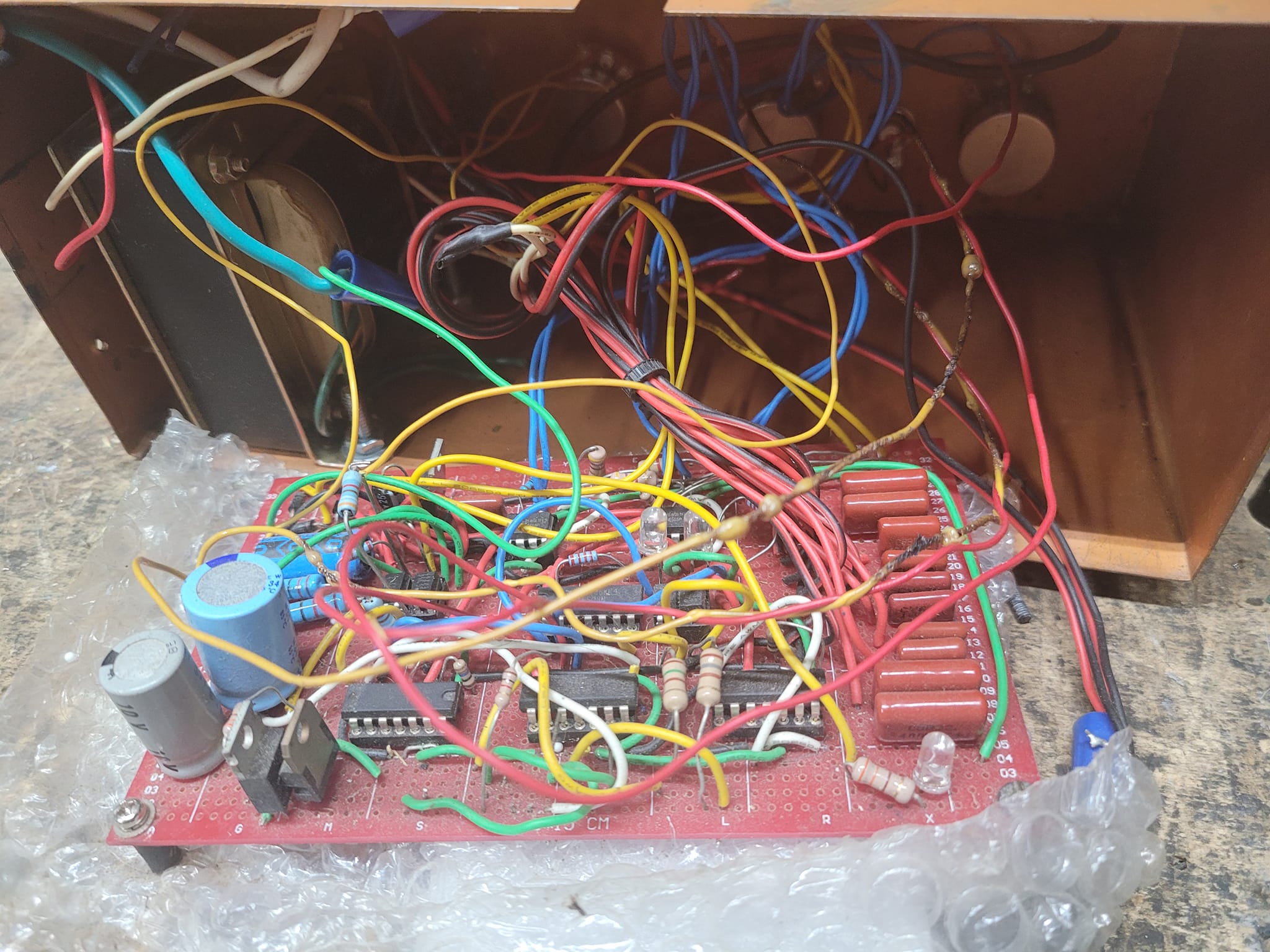](http://stanslegacy.com/uploads/images/gallery/2022-06/ng4cjLDZ1ZZuLOpg-255806338-4705169809505836-119894751386171394-n.jpg) |
| [](http://stanslegacy.com/uploads/images/gallery/2022-06/fZaWqHktg8MjxfZz-77026487-2720040918018745-400836674826797056-n-1.jpg) |
|
[Max Millers' 9XA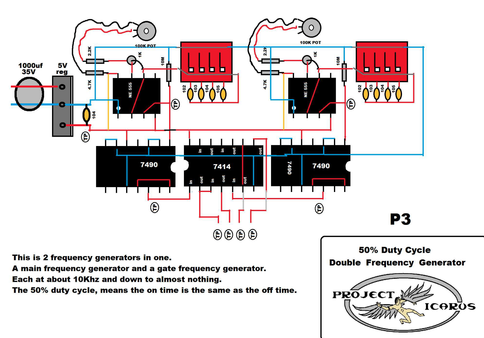](http://stanslegacy.com/uploads/images/gallery/2022-06/7Gg3xEPmyRl4M31B-image-1656200942895-49-00.png)
A funny video illustrating how I still had much to learn about building circuits :)
More progress on the 9XA. Learning how proper transistor biasing and loading is important for controlling amplitude modulation.
# Crossover Voltage Switch
[](http://stanslegacy.com/uploads/images/gallery/2022-06/ENFGcmHuGjdqHbv2-109308463-3285262641496567-1211971226813383673-n.jpg)
# 8XA Alternator Setup
This was an old attempt at using an unrectified alternator's 3 phase output running from a 1/3 HP AC synchronous motor.
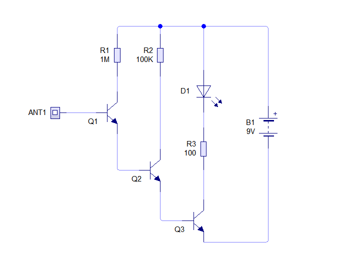
# DIY EMF Detector
Easy homemade EMF probe. I added a piezo buzzer to mine, and found it very helpful to "listen" to the fields coming off of things like wires and HV bulbs, and water capacitors.
**DIY Guide**: [https://www.instructables.com/Make-a-Ghost-Detector/](https://www.instructables.com/Make-a-Ghost-Detector/)
[](http://stanslegacy.com/uploads/images/gallery/2022-06/mspBJd7o7Nk3y2D1-f2ve0jkj153yctj.webp)
# Magnetic Amplifiers
# Saturation Oscillator
You must *listen* to your energy. It plays notes. Once you learn to trigger those notes, you can play a chord.
Playing with distributed inductances and capacitances and harmonics generated from 60 Hz line noise. Using resistive dampening to load mutually coupled transformers inline with the magnetic amplifier's reactive side.
# Magamp LFO standing wave oscillator
# Introducing harmonics into Amplitude Modulation
# Bubbles
# Everything Vibrating in a WFC
This shows Max's Double Barrel cell holder adapted to mount electrodes at opposing ends of each tube.
Tiny streams of nanobubbles can be seen coming from the bolt threads
# Demonstrating High Voltage present at the WFC
##### "Waterless" energy transfer
##### Visualizing standing waves occurring across the WFC capacitor.
# 4 Channel 12AX7 Toroidal Amplitude Modulator
Early Build pics of the 4 Channel modulator.
| [](http://stanslegacy.com/uploads/images/gallery/2022-06/Br7jTZdMwEqqqThb-133798005-3767217696634390-7095165259752784715-n.jpg)
| [](http://stanslegacy.com/uploads/images/gallery/2022-06/DAuPb2JAXEN1Eh0X-134047555-3767217633301063-1100532127399627698-n.jpg)
|
| [](http://stanslegacy.com/uploads/images/gallery/2022-06/x9hGxkifCOZ4SCES-133600591-3767218093301017-8668741515042871589-n.jpg)
| [](http://stanslegacy.com/uploads/images/gallery/2022-06/fIFTguWRq1yjXP1X-133708014-3767218326634327-3937906867011726984-n.jpg) |
# 12AX7 Dual Triode operating in Heptode Mode
Truly Analog Amplitude Modulation AND Gating
[](http://stanslegacy.com/uploads/images/gallery/2022-06/YIcm858HctYjx3Ly-125466214-3650706548285506-994606898162063674-n.jpg)
# 50W PushPull Tube Amp for driving a VIC
[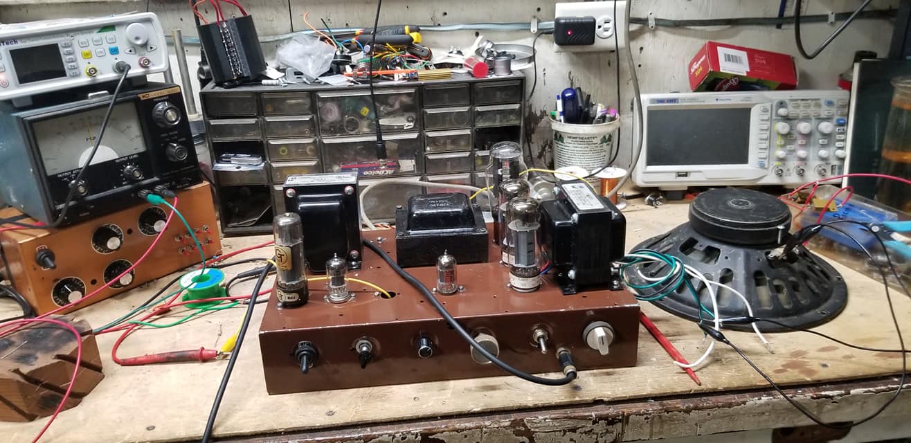](http://stanslegacy.com/uploads/images/gallery/2022-06/o6B2qAzwlwbpXhjj-74176231-2666543493368488-4586020633896288256-n.jpg)
[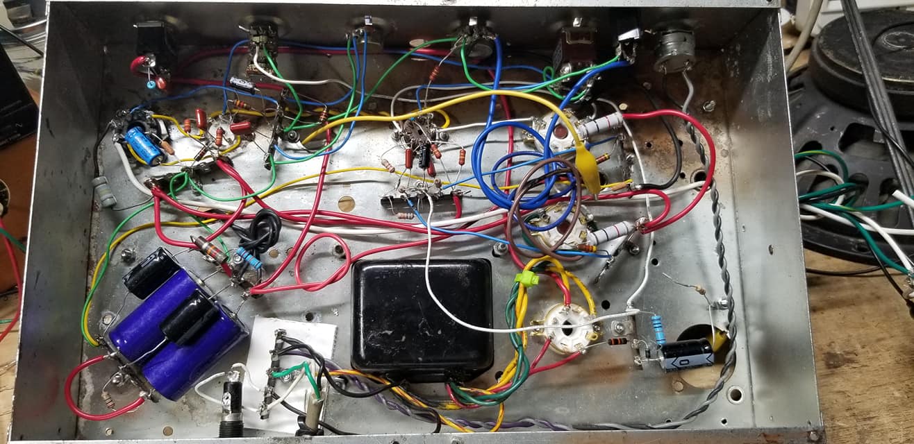](http://stanslegacy.com/uploads/images/gallery/2022-06/KDKdOtkGg8UoEghw-73019663-2666543533368484-3939437153141915648-n.jpg)
# Arduino / ESP32 Projects
# ESP32 - Complex Waveform Generator [LEGACY]
### Setting Up The App
##### Modify ESP C+ Code to configure local network settings
1. 1. Determine your local network's Subnet range (It should be one of these: 10.0.0.0/8, 192.168.0.0/16, or 172.xxx.xxx.xxx)
1. See: [https://www.businessinsider.com/how-to-find-ip-address-of-router](https://www.businessinsider.com/how-to-find-ip-address-of-router)
2. Write down the address of your Gateway (your Router's IP address)
2. Find a free DHCP issued internal IP address on your local network (Guess an IP not in use by picking a number between 100 and 255 for the very last position in your subnet: 192.168.1.xxx)
3. Find your WIFI SSID and Password
1. SSID = The name of your Wifi Connection as your Phone or PC would see it on the network connection browser
2. Password = Your Wifi Password
4. Configure the IP, Gateway and your Wifi SSID & credentials into the ESP code below
1. Preview Of areas to change in code below:
```C++
// #### Change Me ####
const char *SSID = "NETGEAR";
const char *PWD = "12345678";
// Don't Change Me
const char *ASSET_HOST = "https://wavegenjs.s3.amazonaws.com";
// Web server running on port 80
WebServer server(80);
// #### CHANGE ME ####
// Set your Static IP address
IPAddress local_IP(192, 168, 1, 8);
// Set your Gateway IP address
IPAddress gateway(192, 168, 1, 1);
```
5. Copy the full script (down below) and paste it into your Arduino IDE
1. See: [https://randomnerdtutorials.com/how-to-install-esp8266-board-arduino-ide/](https://randomnerdtutorials.com/how-to-install-esp8266-board-arduino-ide/)
6. Compile and Upload the code to the ESP32
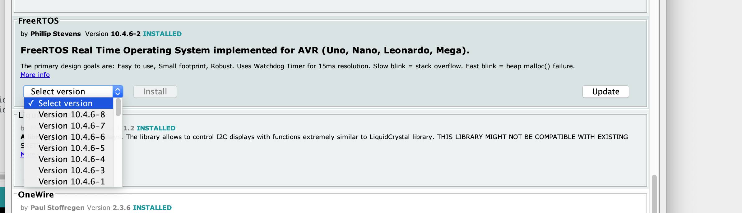
1. Install required libraries (FreeRTOS, ArduinoJSON, Wifi, and WebServer.)
1. See: [https://docs.arduino.cc/software/ide-v1/tutorials/installing-libraries](https://docs.arduino.cc/software/ide-v1/tutorials/installing-libraries)
2. [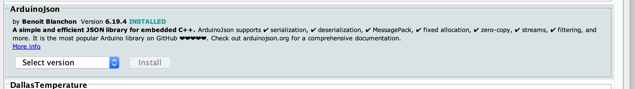](http://stanslegacy.com/uploads/images/gallery/2022-08/dm3BHay59TS8NGay-298171574-5523327307690078-4273704313364637631-n.jpg)
3. [](http://stanslegacy.com/uploads/images/gallery/2022-08/SCMvDM6ZTF2gTCWJ-298253535-5523321941023948-4638314484689292979-n.jpg)
2. Observe the Serial Monitor Log output from the Arduino IDE
3. Confirm network connectivity was established with your router.
7. Connect 2 separate Oscilloscope probes to pins "0" and "2" to ground, on your ESP.
8. Open a web browser on a computer connected to the same internal network as the ESP was given
1. Go to the ESP's given IP Address: [http://192.168.1.8](http://192.168.1.8)
9. Enjoy! (if it works)
##### Troubleshooting:
View the Console Log for errors in your browser while clicking the app's sliders buttons etc..
[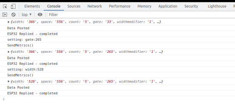](http://stanslegacy.com/uploads/images/gallery/2022-08/VUxhtVg24Ps11Wlw-screenshot-from-2022-08-06-13-24-55.png)
[https://www.browserstack.com/guide/inspect-element-in-chrome#:~:text=One%20of%20the%20easiest%20ways,%2C%20Sources%2C%20and%20other%20tools](https://www.browserstack.com/guide/inspect-element-in-chrome#:~:text=One%20of%20the%20easiest%20ways,%2C%20Sources%2C%20and%20other%20tools).
Confirm the ESP is a connected host in your network and was given the IP you specified
[https://www.wikihow.com/See-Who-Is-Connected-to-Your-Wireless-Network](https://www.wikihow.com/See-Who-Is-Connected-to-Your-Wireless-Network)
#### ESP C+ Code
Expand
```C++
#include
#include
#include
#include
#include
TaskHandle_t pulseTaskHandle;
// #### Change Me ####
const char *SSID = "NETGEAR";
const char *PWD = "12345678";
// Don't Change Me
//const char *ASSET_HOST = "https://wavegenjs.s3.amazonaws.com";
const char *ASSET_HOST = "http://192.168.1.2";
// Web server running on port 80
WebServer server(80);
// #### CHANGE ME ####
// Set your Static IP addres
IPAddress local_IP(192, 168, 1, 8);
// Set your Gateway IP address
IPAddress gateway(192, 168, 1, 1);
IPAddress subnet(255, 255, 255, 0);
IPAddress primaryDNS(8, 8, 8, 8); //optional
IPAddress secondaryDNS(8, 8, 4, 4); //optional
// JSON data buffer
StaticJsonDocument<500> jsonDocument;
char buffer[500];
// env variable
float width = 150;
float space = 150;
float width1 = 0;
float space1 = 0;
float widthelongationmodifier = 1;
float spaceelongationmodifier = 1;
float gate = 1;
int count = 5;
int enablegate = 1;
int channels = 2;
int reference1 = LOW;
int reference2 = HIGH;
int enablealternate = 0;
int invertOne = 0;
int invertTwo = 0;
int ch1lastState = LOW;
int ch2lastState = LOW;
void connectToWiFi() {
Serial.print("Connecting to ");
Serial.println(SSID);
// Configures static IP address
if (!WiFi.config(local_IP, gateway, subnet, primaryDNS, secondaryDNS)) {
Serial.println("STA Failed to configure");
}
WiFi.begin(SSID, PWD);
while (WiFi.status() != WL_CONNECTED) {
Serial.print(".");
delay(500);
}
Serial.print("Connected. IP: ");
Serial.println(WiFi.localIP());
}
void setup_routing() {
server.enableCORS();
server.on("/metrics", getMetrics);
server.on("/set", HTTP_POST, handlePost);
server.on("/", getIndex);
server.begin();
}
void create_json(float width, float space, float count, float gate, float enablegate, float channels, float widthelongationmodifier, float spaceelongationmodifier, float enablealternate, int invertOne, int invertTwo) {
jsonDocument.clear();
jsonDocument["width"] = width;
jsonDocument["space"] = space;
jsonDocument["widthelongationmodifier"] = widthelongationmodifier;
jsonDocument["spaceelongationmodifier"] = spaceelongationmodifier;
jsonDocument["count"] = count;
jsonDocument["gate"] = gate;
jsonDocument["enablegate"] = enablegate;
jsonDocument["channels"] = channels;
jsonDocument["enablealternate"] = enablealternate;
jsonDocument["invertOne"] = invertOne;
jsonDocument["invertTwo"] = invertTwo;
serializeJson(jsonDocument, buffer);
}
String getHtml() {
String ptr = " \n";
ptr +="\n";
ptr +="ESP32 Complex Waveform Generator\n";
ptr +="";
ptr +="";
ptr +="";
ptr +="";
ptr +="\n";
return ptr;
}
void getIndex() {
server.send(200, "text/html", getHtml());
}
void getMetrics() {
create_json(width, space, count, gate, enablegate, channels, widthelongationmodifier, spaceelongationmodifier, enablealternate, invertOne, invertTwo);
server.send(200, "application/json", buffer);
}
void handlePost() {
if (server.hasArg("plain") == false) {
Serial.println("no plain mode");
}
String body = server.arg("plain");
deserializeJson(jsonDocument, body);
width = jsonDocument["widthtotal"];
space = jsonDocument["spacetotal"];
widthelongationmodifier = jsonDocument["widthelongationmodifier"];
spaceelongationmodifier = jsonDocument["spaceelongationmodifier"];
count = jsonDocument["count"];
gate = jsonDocument["gatetotal"];
enablegate = jsonDocument["enablegate"];
channels = jsonDocument["channels"];
invertOne = jsonDocument["invertOne"];
invertTwo = jsonDocument["invertTwo"];
enablealternate = jsonDocument["enablealternate"];
serializeJson(jsonDocument, buffer);
server.send(200, "application/json", buffer);
}
void customDelay(long delayValue)
{
long i = 0;
int x = 0;
for(i=0;i