European Patents
- EP0086439A1 Hydrogen Gas Injection System for Internal Combustion Engine
- EP0086439B1 Hydrogen Gas Injection System for Internal Combustion Engine
- EP0098897A2 Electrical Generator Utilizing Magnetized Particles
- EP0098897A3 Electrical Generator Utilizing Magnetized Particles
- EP0101761A2 Controlled Hydrogen Gas Flame
- EP0101761A3 Controlled Hydrogen Gas Flame
- EP0101761B1 Controlled Hydrogen Gas Flame
- EP0103656A2 Resonant Cavity for a Hydrogen Generator
- EP0103656A3 Resonant Cavity for a Hydrogen Generator
- EP0106917A1 Gas Electrical Hydrogen Generator
- EP0111573A1 Hydrogen Generator System
- EP0111574A1 Hydrogen Generator System
- EP0111574B1 Hydrogen Generator System
- EP0122472A2 Hydrogen Aeration Injection System
- EP0122472A3 Hydrogen Generator System
- EP0333854A4 Hydrogen Generator System
- EP0381722A4 Hydrogen Aeration Injection System
- Full Patent List
EP0086439A1 Hydrogen Gas Injection System for Internal Combustion Engine
EP0086439B1 Hydrogen Gas Injection System for Internal Combustion Engine
EP0098897A2 Electrical Generator Utilizing Magnetized Particles
PDF Download: SMeyer-EP0098897A2-Electrical_Generator_Utilizing_Magnetized_Particles.pdf
European Patent Office
Office européen des brevets
Application number: 82711895.3
Date of filing: 14.12.82 0 098 897 A2
Publication number: EUROPEAN PATENT APPLICATION &) int.cl3: H 01 F 31/00
Priority: 09.04.82 US 367051 ® Date of publication of application: 25.01.84 Bulletin 84/4
Designated Contracting States: AT BE CH DE FR GB IT LI LU NL SE
® Applicant: Meyer, Stanley A. 3792 Broadway Grove City Ohio 43123(US)
@ Inventor: Meyer, Stanley A. 3792 Broadway Grove City Ohio 43123[US)(3) Representative: Wasmeier, Alfons, Dipl.-Ing. et al, Postfach 382 Greflingerstrasse 7 D-8400 Regensburg{DE)
Electrical generator utilizing magnetized particles
An electrical particle generator comprising a non-magnetic pipe in a closed loop having a substantial amount of magnetized particles encapsulated therein. A magnetic accelerator assembly positioned on said pipe having an inductive primary winding and a low voltage input to said winding. A secondary winding positioned on said pipe Opposite to said primary winding. Upon voltage being applied to said primary winding said magnetized particles are passed through said magnetic accelerator assembly with increased velocity. The velocity accelerated particles continuing through said pipe induce an electrical voltage/current potential as they pass through the secondary winding. The increased secondary voltage is utilized in an amplifier arrangement.
Illustrations
 |
|
 |
|
|
|
|
|
|
|
|
|
|
|
|
ABSTRACT
An electrical particle generator comprising a non-magnetic pipe in a closed loop having a substantial amount of magnetized particles encapsulated therein. A magnetic accelerator assembly positioned on said pipe having an inductive primary winding and a low voltage input to said winding. A secondary winding positioned on said pipe opposite to said primary winding. Upon voltage being applied to said primary winding said magnetized particles are passed through said magnetic accelerator assembly with increased velocity. The velocity accelerated particles continuing through said pipe induce an electrical voltage/current potential as they pass through the secondary winding. The increased secondary voltage is utilized in an amplifier arrangement,
BACKGROUND AND PRIOR ART
The prior art teachings expound the fundamental principle that a magnetic field passing through inductive windings will generate a voltage/current or enhance the voltage there across if the winding is a secondary winding.
It is also taught by the prior art that a magnetic element in a primary inductive field will be attracted at one end of the coil and repelled at the other. That is a moving magnetic element will be accelerated in motion by the attraction and repulsion of the magnetic field of the primary inductive winding.
In the conventional step-up transfer the voltage across will impart further magnetic force to the particles. This magnetic attraction and the repulsion considerably enhances - the motion of the discrete particles within the pipe. The particles are ejected from the area of the accelerator with an increased velocity motion.
The magnetic elements proceed in the closed loop pipe at a speed considerably greater than their normal movement due to the accelerator action. As the magnetic elements pass through the core of the secondary winding there is induced a voltage therein. In this way a much greater voltage is induced in the secondary winding of the transformer.
OBJECTS
It is principal object of the present invention to provide an electrical generator capable of producing a voltage/current much greater in magnitude hereintofore possible.
Another object of the present invention is to provide such an electrical generator utilizing magnetized elements and a magnetic accelerator.
Another object of the present invention is to provide such an electrical generator that can control the amplitude of the output.
Another object of the present invention is to provide such an electrical generator that may be utilized with direct current, alternating current, pulsed, or other configurations of waveforms.
Another object of the present invention is to provide such an electrical generator that may be utilized in a single phase or three phase electrical system.
Still another object of the present invention is to provide a generator for developing magnetized particles for use in an electrical particle accelerator.
A further object of the present invention is to provide such an electrical generator that utilizes components readily available are adaptable to a simplified embodiment.
Other objects and features of the present invention will become apparent from the following detailed description where taken in conjunction with the drawings in which:
BRIEF DESCRIPTION OF DRAWINGS
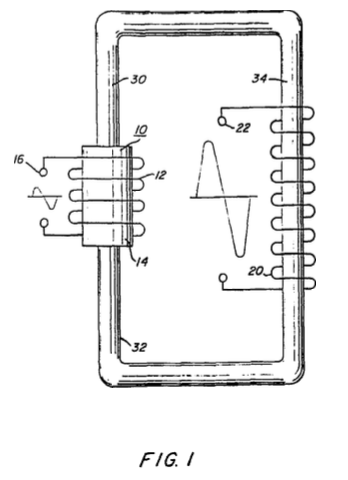
Figure 1 is a simplified illustration of the principles of the invention shown partly in crossection and partly pictorially.
Figure 2 is an electrical schematic illustration of the embodiment of Figure 1.
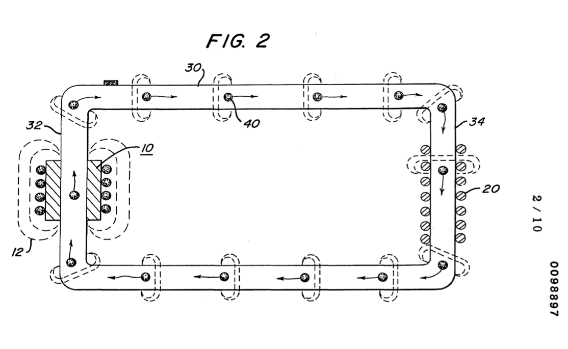
Figure 3 is an illustration similar to Figure 2 but adaptable to 3 phase.
Figure 4 is a first alternative arrangement in a preferred illustration of the invention.
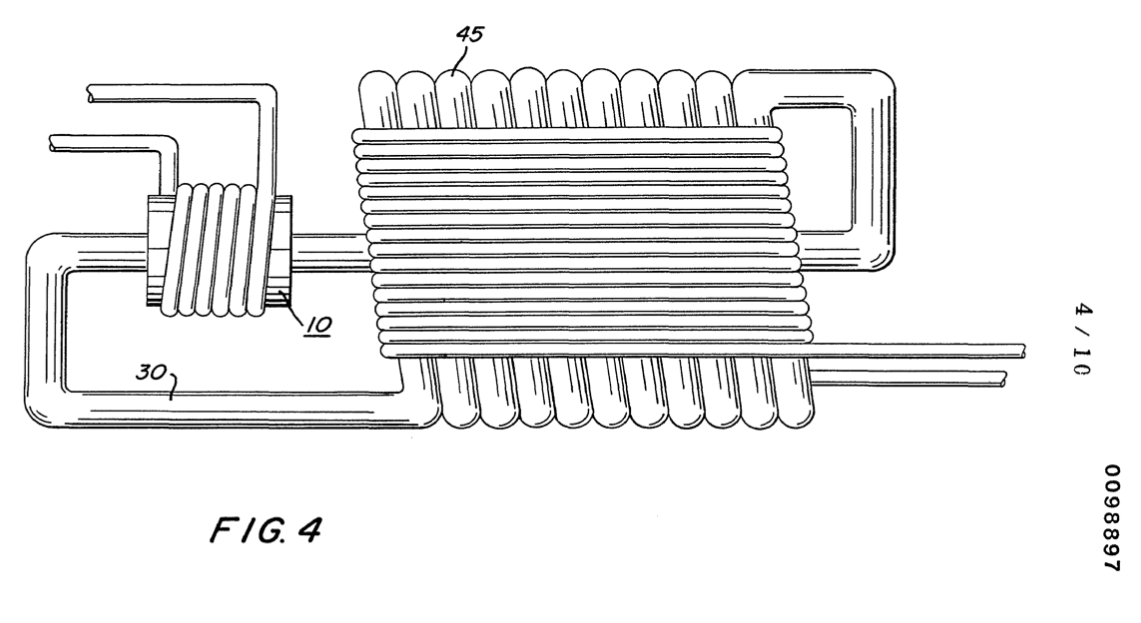
Figure 5 is another alternative arrangement in a preferred illustration of the invention.

Figure 6 is another alternative arrangement in a preferred illustration of the invention.
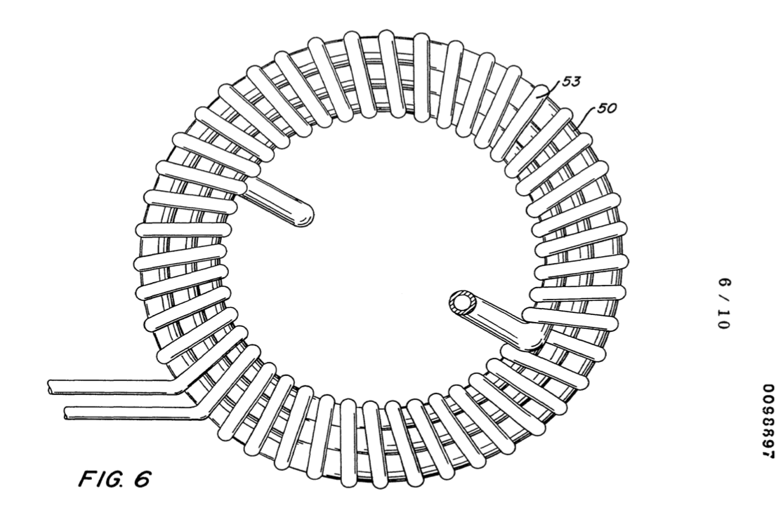
Figure 7 is another alternative arrangement in a preferred illustration of the invention.

Figure 8 is another alternative arrangement in a preferred illustration of the invention.
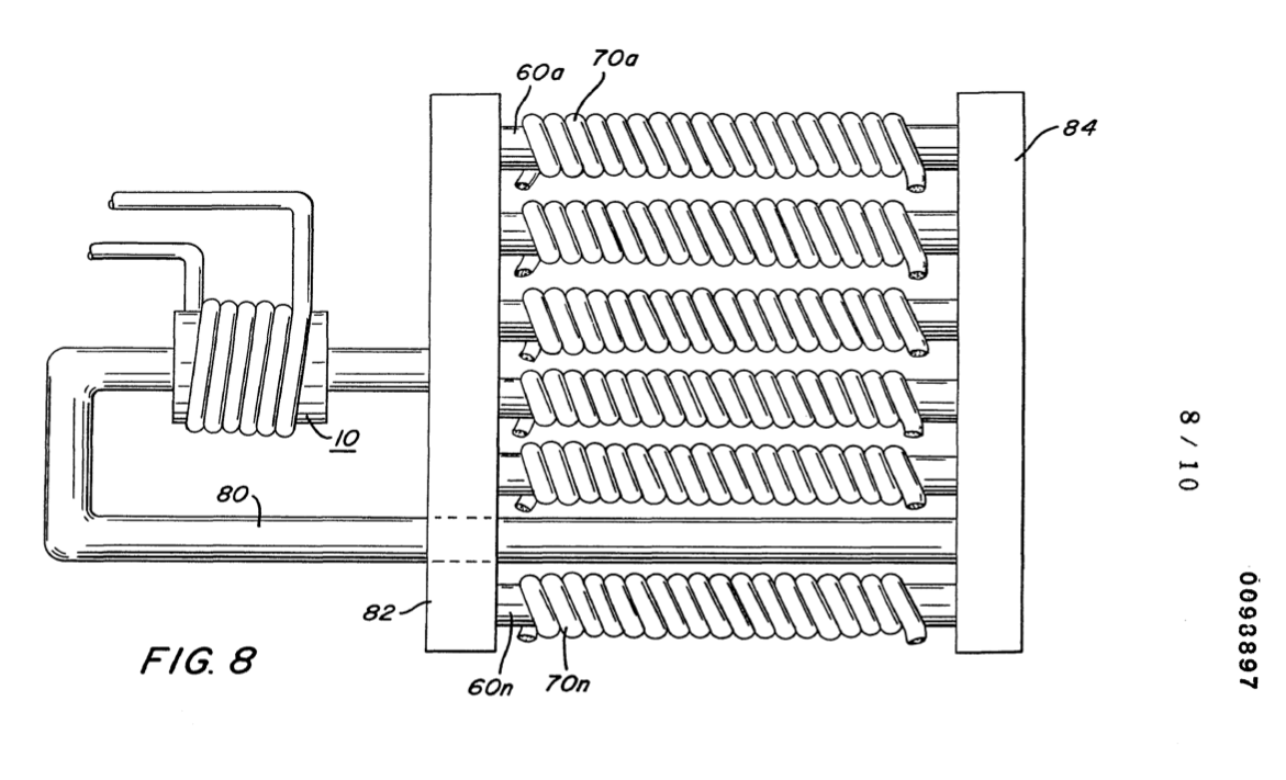
Figure 9 is an alternative arrangement for a magnetic drive accelerator assembly.
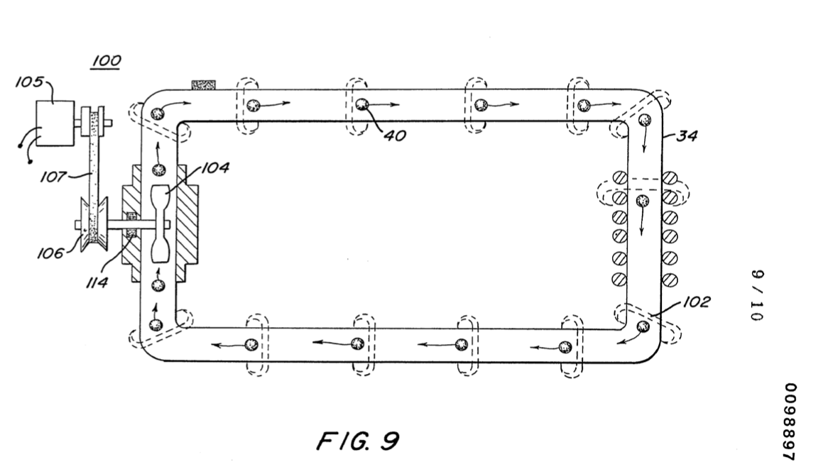
Figure 10 is a mechanical illustration of a magnetic particle generator for developing magnetic particles utilized in the present invention.
DETAILED DESCRIPTION OF INVENTION
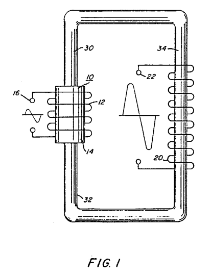
With particular reference to Figures 1 and 2 there is illustrated the invention in its mostly simplified schematic embodiment.
|
|
The system of the invention comprises a primary winding coil magnetic accelerator assembly 10, a closed loop non-magnetic pipe 30, and a secondary winding 20.
The magnetic accelerator assembly comprises primary windings 12 a magnetic core 14 and voltage taps 16. The primary windings are positioned around end 32 of closed loop pipe 30 or tubing of non-magnetic material.
At the opposite end 34 of the closed loop pipe 30 there is positioned thereon secondary windings 20.° A voltage tap 22.on secondary winding 20 permits the utilization of the voltage induced therein.
Within the pipe 30 there is encapsulated a substantial quantity of magnetic elements 40 of Figure 2. The elements 40 must be sufficiently light to be freely mobile. Therefore, the elements may be particles suspended in a fluid medium such as gas, liquid, or light-weight movable solid particles and more preferably gas. In the application of suspended solid magnetic particles it may be desirable to evacuate the tubing to reduce the resistance to its flow. The magnetized elements 40 are discrete elements, that is, each particle or a minuscule part thereof is separately magnetized. Further, the action as hereinafter described is an action upon each particle and not upon the mass.
The voltage applied to terminals 16 of the primary winding 12 is a low voltage the magnitude of which may be utilized as an input signal control. By varying the input voltage the accelerator will vary the velocity of the speed of the particles; which, in turn vary the magnitude of the voltage/current output of the secondary winding 20.
The output 22 of the secondary transformer 20 is a high voltage/current output.
It can be appreciated that the system of Figures 1 and 2 utilizing a single closed loop will provide a single phase output in the secondary winding. With particular reference to Figure 3 there is illustrated a closed loop system having three parallel non-magnetic tubes 31, 33, and 35. On each tube or pipe there is a respective secondary winding 21, 23, and 25.
Each of the secondary windings 21, 23, and 25 are a single phase much as that shown in Figures 1 and 2. The three pipes, having a common junction at its input and at its output, with the respective three secondary pick-up windings provide a balance three-phase (3) electrical system.
The electrical power generator illustrated in Figure 4 is in electrical operation identical to that in Figures 1 and 2. The physical configuration of the arrangement is adapted to be utiliz- ed in a high moisture environment. An insulating coating 45 completely covers the pipe 30, as well as all electrical windings.
In Figure 4 there is illustrated that increasing the number of coils with a given size winding the voltage/current output is increased. The physical configuration illustrated is such that the vertical aspects as well as the horizontal aspect are utilized. In this way a large diameter pipe can be used with a substantial number of turns of heavy-gauge high-current wire.
With particular reference to Figure 5 there is illustrated a coil arrangement 49 that utilizes the entire magnetic flux in the closed loop tubing 47. The configuration is that of a coaxial arrangement with the primary winding 43 as a center core.
Figure 6 illustrates a concentric spiral configuration of the tubing 50 having the secondary windings 53 wound over it's entirety. In Figure 7 the particle accelerator 10 is wound over the tubing 30 much in the same manner as the Figures 1 and 2.
|
|
However, in this embodiment the tubing 30 is a continuous closed loop but in a series, parallel configuration. That is electrically there are three secondary windings with three outputs whereas the tubing 30 is in series through the three secondary windings. In Figure 8 the reverse of that configuration of Figure 7 is shown. That is the several pick-up coils are wound in series; whereas the tubing 80 is not a continuous tubing as that of the other configuration. Principally, there is disclosed an input manifold 82 and an output manifold 84 with the several tubings 60a xxx n interconnecting the two manifolds. Each one of the aforesaid secondary coils 70a xxx n are wound over its respective tubing.
The magnetic particle accelerator 10 may comprise configurations and structures distinctive from the electrical accelerator of Figure 1. With reference to Figure 9 there is illustrated a mechanical particle accelerator 100. In this embodiment the Magnetic particles 102 are permanently magnetized prior to being encapsulated in non-magnetic pipe 110. The particles 102 are accelerated by fan blade or pump 104 rotated by mechanical drive assembly 106. The mechanical drive for the assembly 106 may comprise a pulley 112 attached by a belt or like to an electric motor. A sealing bearing 114 retains the particles 102 within the pipe 110.
It was stated above, the particles traversing the secondary coils a voltage/current is generated therein. It must be appreciated that the particles are not in actuality traversing the coils but are in fact traversing the magnetic field of the coils.
Again, the pipe 30 is described as a non-magnetic pipe. There are certain non-magnetic pipes that would not be operable in the present invention. That is, the pipe 30 must be capable of passing magnetic lines of force; and that it is these magnetic lines of force that traverse the inductive field of the secondary windings 20 to induce a voltage/current therein.
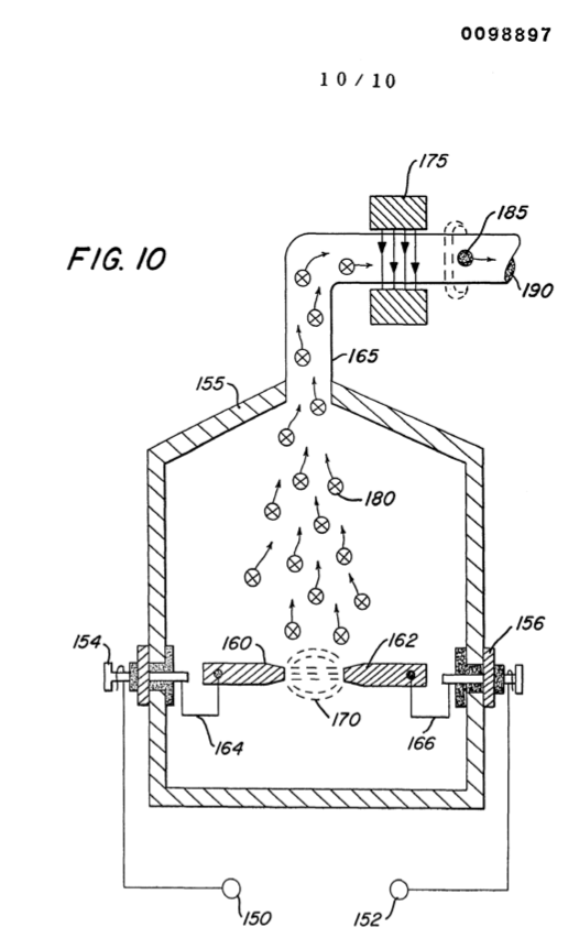
A significant feature of the invention illustrated in the various embodiments hereintofore described, as the generation of the magnetized particles encapsulated in the tubing. With reference to Figure 10, there is illustrated apparatus for carrying out the process of vaporizing material into vaporized particles and thereafter magnetizing the particles by subjecting them to a magnetic field.
The chamber 155 is a vacuated chamber haying positioned in its lower half portion a pair of electrodes 160 and 162 of magnetizable material. A source of voltage 150 and 152 provides voltage and current of opposite polarity via terminals 154 and 156 to the electrodes 160 and 162 via wire connections 164 and 166. The area 161 between the end of the electrodes 160 and 162 is the spark gap.
Upon the application of power to the magnetizable material electrodes 160 and 162 the tip of the electrodes in the spark gap will be vaporized into particles 180.
The particles 180 rise, use and enter into non-magnetic pipe 165. As the particles progress in movement they pass between the magnetic field generator 175. The particles each take on a magnetic charge as magnetized particles 185 and there- after are discharged via port 190 to the electrical particle generator above described.
In the simplified preferred embodiment of Figures 1 and 2, as well as the referred preferred embodiments it was indicated that a low voltage was applied to the particle accelerator 10. Upon acceleration a high voltage/current would be induced in the secondary pickup coil 20. A most significant advantage of the present invention is that the voltage amplification is irrespective to the wave-shape of the input voltage. Specifically, if the input voltage is direct current a direct current voltage will be at the output; an alternating voltage will result in an alternating voltage at the output; a pulsed voltage will result in a pulsed voltage at the output; and a voltage of any other configuration will result in a similar configuration at the output.
Although certain embodiments have been shown it is to be understood modifications may be had without departing from the spirit and scope of the invention.
|
|
CLAIMS
1. An electrical particle generator comprising;
a non-magnetic closed-loop tubing, passing magnetic lines of force,
a particle accelerator positioned adjacent to one end of said tubing,
a secondary inductive winding positioned adjacent to said tubing opposite to the position of said accelerator,
a substantial volume of magnetized elements encapsulated in said tubing;
said accelerator having means to provide a low input voltage; and
said secondary winding having means for tapping a high voltage/current for utilization.
2. The electrical particle generator of Claim 1 wherein said magnetized elements are particles suspended in a fluid medium.
3. The electrical particle generator of Claim 2 wherein said magnetized elements is a gas.
4, The electrical particle generator of Claim 2 wherein said magnetized elements is a liquid,
5. The electrical particle generator of Claim 2 wherein said magnetized elements is a solid.
6. The electrical particle accelerator of Claim 1 wherein said particle accelerator is an electrical magnetic particle accelerator.
-2- 7. The electrical particle generator of cPL9 FEB hein said particle accelerator further comprises a primary inductive winding, and a low voltage input to said winding.
8. The electrical particle generator of Claim 4 wherein said low voltage input is a variable voltage input for controlling the magnitude of the voltage/current induced in said secondary winding.
9. The electrical particle generator of Claim 4 wherein said input voltage to said primary winding is direct current, and wherein said output voltage is a direct current/voltage.
10. The electrical particle generator of Claim 4 wherein said input voltage to said primary winding is alternating current and wherein said output current/voltage is an alternating current/voltage.
11. The electrical particle generator of Claim 4 wherein said input voltage to said primary winding is pulsed, and wherein said output current/voltage is a pulsed current/voltage.
12. The electrical particle generator of Claim 4 wherein said input voltage to said primary winding has variable waveform, and wherein said output.current/voltage will have a similar waveform as said input voltage waveform.
13. The electrical particle generator of Claim 4 wherein said particle accelerator further comprises a magnetic forming core, and wherein said core has an opening slightly greater than the outside diameter of said tubing and adapted to receive the same.
14. The electrical particle generator of Claim 1 said tubing has at said opposite end three parallel discrete branches and wherein said secondary coil is three discrete coils with three discrete outputs one of each positioned over one of each of said tubing branches thereby providing a three phase output.
15. The electrical generator of Claim 1 wherein said particle accelerator comprises mechanical pump means, and wherein said magnetized elements are permanently magnetized elements.
16. An assembly for providing a magnetized particle for utilization in an electrical particle generator comprising a chamber and a pair of magnetizable material electrodes positioned therein,
a source of voltage/current of opposite polarity applied to said electrodes,
said magnetizable material becoming vaporized upon the application of said voltage/current in said electrodes,
a pipe connected to said chamber, and means directing said vaporized particles to said pipe,
a magnetic field generator having the other end of said pipe positioned within its magnetic field,
and wherein said vaporized particles entering and being expelled through said pipe become magnetized by passing through said magnetic field generator.
EP0098897A3 Electrical Generator Utilizing Magnetized Particles
Source: SMeyer-EP0098897A3-Electrical_Generator_Utilizing_Magnetized_Particles.pdf
Electrical generator utilizing magnetized particles
 An electrical particle generator comprising a non-magnetic pipe (30) in a closed loop having a substantial amount of magnetized particles (40) encapsulated therein.
A magnetic accelerator assembly (10) positioned on said pipe having an inductive primary winding (12) and a low voltage input to said winding.
A second winding (20) positioned on said pipe opposite to said primary winding.
Upon voltage being applied to said primary winding said magnetized particles are passed through said magnetic accelerator assembly with increased velocity.
The velocity-accelerated particles continuing through said pipe induce an electrical voltage-current potential as they pass through the secondary winding.
The increased secondary voltage is utilized in an amplifier arrangement.
EP0101761A2 Controlled Hydrogen Gas Flame
Europäisches Patentamt
European Patent Office
Office européen des brevetsPublication number: 0 101 761 A2
Source: SMeyer-EP0101761A2-Controlled_Hydrogen_Gas_Flame.pdf
EUROPEAN PATENT APPLICATION
- Application number: 82111597.9
- Date of filing: 14.12.82
- Priority: 25.08.82 US 411977
- Date of publication of application: 07.03.84 Bulletin 84/10
- Designated Contracting States: AT BE CH DE FR GB IT LU NL SE
Applicant: Meyer, Stanley A.
3792 Broadway
Grove City Ohio 43123 (US)Inventor: Meyer, Stanley A.
3792 Broadway
Grove City Ohio 43123 (US)Representative: Wassmiller, Alfons, Dipl.-Ing. et al.
Postfach 322 Gräfingerstrasse 7
D-8400 Regensburg (DE)
(54) Controlled hydrogen gas flame.
(A) A sustained controllable gas flame.
The hydrogen generator utilized is that for separating gasses from water having impurities and other gasses entrapped therein.
The gasses separated from the water comprises hydrogen, oxygen, and the non-combustible gasses, such as nitrogen.
The nitrogen, oxygen, and hydrogen are mixed as they are released in the process by the generator and collected as the mixture of gasses in the collection chamber of the generator.
The method and system comprises a nozzle of a given configuration connected through a line to the uppermost region of the gas collection chamber of the hydrogen generator.
The nitrogen reduces the velocity and temperature of the burning flame from that of the hydrogen/oxygen mixture.
To further control the temperature and velocity of the burning gas mixture there is added to the collection chamber other non-burnable gasses.
The configuration of the nozzle and its port opening is dependent on the mixture of gasses utilized and restricted thereby.
An increase in the size of the flame requires additional port openings to prevent blowout.
CROSS REFERENCE:
The hydrogen/oxygen generator utilized in the present invention is that disclosed and claimed in my co-pending U.S. patent application, Serial Number: 302,807, filed: September 16, 1981, for: HYDROGEN GENERATOR SYSTEM.
In that process for separating hydrogen and oxygen atoms from water having impurities, the water is passed between two plates of similar non-oxidizing metal.
No electrolyte is added to the water.
The one plate has placed thereon a positive potential and the other a negative potential from a very low amperage direct-current power source.
The sub-atomic action of the direct current voltage on the non-electrolytic water causes the hydrogen and oxygen atoms to be separated — and similarly other gasses entrapped in the water such as nitrogen.
The contaminants in the water that are not released are forced to disassociate themselves and may be collected or utilized and disposed of in a known manner.
The direct current acts as a static force on the water molecules; whereas the non-regulated rippling direct current acts as a dynamic force. Pulsating the direct current further enhances the release of the hydrogen and oxygen atoms from the water molecules.
 |
|
Controlled Hydrogen Gas Flame
PRIOR ART:
The electrolysis process for generating hydrogen and oxygen gas is well known in the art. It is, of course, further understood with a proper mixture of oxygen gas, the hydrogen gas is combustible and under ideal conditions a flame may be had. Reference is made to U.S. Patent Number: 4,184,921.
However, in that the burning velocity of hydrogen is 265-325 cm./sec. versus 37-45 cm./sec. of that of gasoline, the velocity of hydrogen is so great that the hydrogen ensuing from a nozzle will not under ordinary circumstances sustain a flame.
Therefore, to sustain a flame at a nozzle attached to a hydrogen generator the burning velocity of the hydrogen gas must be reduced.
It has been found that all water in its natural state, whether it be tap water, well water, sea water, or fresh water, is a saturation of ambient air.
Further, in that ambient air contains a substantial amount of nitrogen, all natural water will have entrapped therein nitrogen.
Again, the percentage of nitrogen entrapped in natural water has been determined to be a fixed percentage and very uniform at seventeen (17%) percent --- irrespective of the source of the water or its impurities.
Hence, a natural water gas analysis will show a seventeen percent of nitrogen relative to the hydrogen and oxygen.
The nozzle connected to the collection chamber via an appropriate line has a port opening of a controlled size and configuration, related to the size of the flame and the temperature and velocity of the burning gas mixture.
To maintain the flame, that is to prevent blowout, additional nozzles are included when the overall flame size is to be increased.
OBJECTS:
-
It is accordingly a principal object of the present invention to provide a new and improved hydrogen/oxygen generator that is operable from a water source that provides hydrogen/oxygen output that will have a sustained burn.
-
Another object of the present invention is to provide a hydrogen/oxygen generator that in addition to the hydrogen and oxygen gasses releases non-combustible nitrogen gas capable of reducing the burning velocity and temperature of a pure hydrogen/oxygen flame.
-
A further object of the present invention is to provide a hydrogen generator that includes the controlled addition of other non-combustible gasses to the gas chamber thereof to thereby further control the burning velocity and temperature of the hydrogen gas.
Other objects and features of the present invention will become apparent from a reading of the detailed description of the preferred embodiment taken in conjunction with the single figure drawings in which:
BRIEF DESCRIPTION OF THE DRAWINGS:
-
Figure 1 is a cross-section of a hydrogen generator illustrating the features of the present invention in its most preferred embodiment incorporated therein.
-
Figure 2 schematically shows the increased number of nozzle ports to increase the flame size.
|
|
DETAILED DESCRIPTION OF DRAWINGS:
The hydrogen generator 10 is that of my co-pending patent application, supra. This generator comprises a closed watertight housing 12 having therein natural water 13.
Submerged in the water 13 is a pair of plates 15 (one not shown) having a direct current low amperage voltage, via connector 11, applied thereto.
As set forth in my co-pending patent application, supra, the electrical potential applied to the similar non-oxidizing metal plates is a sub-atomic action.
In this way, the hydrogen atoms 14 and the oxygen atoms are released from the water molecule.
Unlike the electrolysis process for generating hydrogen from distilled water, the hydrogen generator of my aforementioned patent application utilizes water 13 that need not be pure --- simply any water irrespective of contaminants and source.
Natural water such as tap, well, sea, or fresh water is an absorber of ambient air.
Ambient air in turn contains a substantial amount of nitrogen gas.
Water as an absorber of ambient air will entrap seventeen percent (17%) of nitrogen gas; that is, natural water absorbs seventeen percent (17%) of nitrogen gas in comparison to its hydrogen and oxygen gas content.
In operation of the hydrogen generator, in that it is a subatomic or force-type of generator, the gasses in the water will be released.
Therefore, when natural water is used the nitrogen gas will be released together with the hydrogen and oxygen gasses.
In the preferred embodiment utilizing tap water, the nitrogen gasses 16 are intermixed with the hydrogen gasses 14 and the oxygen gasses 18 in the chamber 19 of the hydrogen generator 10.
Upon release of the gasses via line 24 and nozzle 20 and then port 22 the gas mixture is ignited to provide flame 25.
The flame 25 is sustained in that the nitrogen gasses 16 reduce the burning velocity and temperature of the hydrogen gas 14.
A realistic and practical manner of further controlling the burning velocity and temperature of the hydrogen gasses 14 is by adding non-combustible gasses directly to the hydrogen and oxygen gasses generated. This is accomplished
by inlet 30 to the upper gas chamber 19 of the hydrogen generator. Valve means 35 is adjustable to control the amount of non-combustible gasses added to the gas chamber.
The nozzle 20 connected to the chamber 19 of the generator 10 via line 17, is of a given configuration to permit a predetermined quantity of gasses to be expelled from the port 22. The port size is dependent on the gasses generated, and collected in the chamber 19, the pressure of the chamber 19 of the generator 10, and the size of the flame desired.
To increase the size of the flame 25 would appear to be a simple matter of increasing the rate of gasses generated. However, an increase of gasses merely causes a blowout at the port 22 opening of the nozzle 20. This flame blowout will occur since an increase in hydrogen gas generation disrupts the ratio of the initial mixture, even though the percentages remain constant. Typically, tap water will contain 62% hydrogen, 31% oxygen, and 17% nitrogen. In actuality, the percentages may be somewhat less dependent on other gasses that may be trapped in the tap water. The increase in production will not affect the percentages, but it must be appreciated that the volume of the gasses will be proportionately increased. In turn, the volume being directly related to pressure, the pressure will be similarly increased.
To effectively reduce or counter the velocity due to the increased pressure of the hydrogen gas mixture in the chamber 19, a larger port 22 would appear to be capable of handling the increased pressure. But, as aforesaid, a larger port end and the concentration of the high velocity hydrogen gas mixture will cause a flame blowout. To sustain a larger flame with increased pressure, additional nozzles having ports or a nozzle 20 with multiple ports as shown in Figure 2, of a port size predetermined as aforesaid, will be added to the line 17. Accordingly, the larger the desired flame, the greater the number of ports.
It can be understood that a port that will not sustain a flame does present a safety factor relative to hydrogen spark back to the chamber 19. Hence, controlling the size of the port 22 in effect acts as a quencher of hydrogen spark back.
Although certain and specific embodiments are shown and described it is within the scope and spirit of the present invention to include alternatives and modifications thereto.
CLAIMS:
-
A hydrogen/oxygen generator capable of sustaining the controlled burning of the gasses generated thereby comprising:
- a housing having natural water therein including entrapped non-combustible gasses,
- a pair of similar non-oxidizing plates having direct current low amperage voltage applied thereto to provide a sub-atomic, force-type action on said water,
- said action liberating the hydrogen atoms and oxygen atoms from said water molecule, and further liberating said non-combustible gasses from said water,
- a gas collection chamber in said generator for collecting and intermixing said released gasses,
- a nozzle attached to the gas collection chamber of said housing including an inlet for receiving the mixture of hydrogen, oxygen and non-combustible gas,
- said nozzle of a predetermined size and configuration on a port for expelling said mixed gasses, and means for igniting said mixed gasses.
-
The hydrogen/oxygen generator of Claim 1 wherein said non-combustible gas is nitrogen.
-
The hydrogen/oxygen generator of Claim 2 wherein said gasses intermixed in said collection chamber of the hydrogen generator comprise 62% hydrogen, 31% oxygen, and 17% nitrogen.
-
The hydrogen/oxygen generator of Claim 3 wherein said means comprises an inlet connected to said gas collection chamber of said housing, and means for introducing non-combustible gasses to said chamber.
-
The hydrogen/oxygen generator of Claim 4 wherein said inlet further comprises valve means for controlling the amount of non-combustible gasses introduced to said chamber.
-
The hydrogen/oxygen generator of Claim 5 wherein said port on said nozzle of a predetermined size and configuration is related to the ratio of gasses in said collection chamber to provide a flame of a predetermined velocity and size at said port.
-
The hydrogen/oxygen generator of Claim 6 wherein said port size and configuration is maintained with a plurality of ports to thereby permit a proportional increase in flame size.
EP0101761A3 Controlled Hydrogen Gas Flame
EP0101761B1 Controlled Hydrogen Gas Flame
EP0103656A2 Resonant Cavity for a Hydrogen Generator
Source: SMeyer-EP0103656A2-Resonant_Cavity_for_a_Hydrogen_Generator.pdf
Europäisches Patentamt
European Patent Office
Office européen des brevetsPublication number: 0 103 656 A2
EUROPEAN PATENT APPLICATION
- Application number: 82111598.7
- Date of filing: 14.12.82
- Priority: 21.09.82
- Date of publication of application: 28.03.84 Bulletin 84/13
- Designated Contracting States: AT BE CH DE FR GB IT LU NL SE
Applicant: Meyer, Stanley A.
3792 Broadway
Grove City Ohio 43123 (US)Inventor: Meyer, Stanley A.
3792 Broadway
Grove City Ohio 43123 (US)Representative: Wassmiller, Alfons, Dipl.-Ing. et al.
Postfach 322 Gräfingerstrasse 7
D-8400 Regensburg (DE)
Resonant cavity for a hydrogen generator
A direct current voltage exciter for utilization in a non-electrolysis process and apparatus for separating hydrogen/oxygen gas from water.
The non-oxidizing exciter comprises a plate structure with positive potential applied to one such plate and a negative potential applied to the other plate.
The frequency between direct current pulses applied to the plate structure determines the frequency of gas liberation, and the amplitude of the direct current pulses determines gas generation considerably by the sub-atomic action on the resonant structure.
A structure of a resonant unit is described with alternative embodiments of this invention.
In my co-pending patent application, supra, it was shown the hydrogen gas generator is variably increased by varying the construction of the exciters; more particularly, by (1) increasing the area of the plates, (2) reducing the space between the plates, and (3) altering the physical configuration of the plate.
SUMMARY OF INVENTION:
The basic structure of and principals of operation of the aforesaid co-pending patent application are utilized.
The non-oxidizing exciters are of a construction, spherical in a preferred embodiment, with a given spacing between the positive and negative elements to form a resonant cavity at a given frequency.
The direct current voltage is pulsed at a repetition rate (frequency) to match the resonant wavelength.
At the matched frequency, the sub-atomic action of the pulsed direct current voltage is enhanced considerably.
The forceful action on the water molecule causes the molecules to be bombarded and break into its atomic structure at a much more rapid rate; thereafter, the gas atoms are set into motion within the resonant cavity, thereby increasing velocity to a jet-like action as they are released from a port.
The complete resonant cavity has a controlled size port for the release of the high velocity gasses.
The resonant cavity plate structure in a preferred arrangement is an array of elements. The gasses emitted from the array are combined and expelled as high velocity gasses from a common nozzle and utilized.
OBJECTS:
It is a principal object of the present invention to provide an improved structure that enhances the separation of hydrogen/oxygen gasses from water.
A further object of the present invention is to provide such a structure that enhances the sub-atomic action in a non-electrolysis process.
Another object of the present invention is to provide such a structure wherein the sub-atomic action is controlled.
Another object of the present invention is to provide such a structure wherein the velocity of the gasses released by a sub-atomic action are increased considerably.
Other objects and features of the present invention will become apparent from a detailed description of the invention when taken in conjunction with the drawings in which:
BRIEF DESCRIPTION OF DRAWINGS:
-
Figure 1 is a schematic illustration of the structure of the present invention in its most simplified arrangement.
-
Figures 2, 2A, and 2B are a series of waveforms illustrating the pulse rate of the direct current to match the resonant frequency of the structure of Figure 1.
-
Figure 3 is a schematic illustration of the utilization of the structure of Figure 1.
-
Figure 4 is a first alternative structure to that shown in Figure 1.
-
Figure 5 is another alternative structure to that shown in Figure 1.
-
Figure 6 is another alternative structure to that shown in Figure 1.
-
Figures 7 and 7A are an array of exciters, such as shown in Figure 1, in a preferred embodiment.
-
Figure 8 is an array of exciters, such as shown in Figure 3, in a preferred embodiment.
DETAILED DESCRIPTION OF INVENTION:
 Reference is now made to the several figures depicting the preferred embodiment of the present invention.
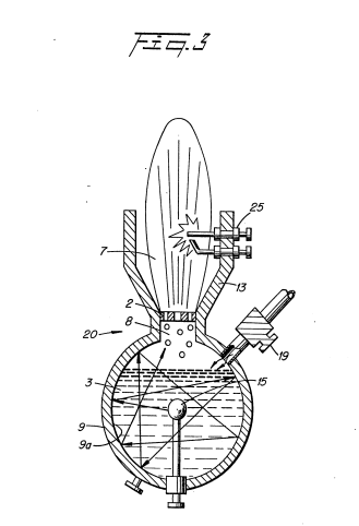
With particular reference now to Figure 1, illustrating the mechanical schematic in a most simplified form of the invention, the housing 10 is a sphere having a gas expulsion opening 8 in its uppermost region, and a gas guide 13 flared out from the opening 8.
Centrally positioned within the sphere 10 is another sphere 15 of much smaller diameter.
The outer shell 9 of the sphere is the grounded negative side.
That is, the negative side of a direct current potential is applied via terminal 16 to the outer shell 9.
To the inner element 15, the direct current positive potential is applied thereto via terminal wire 18 extended through a support element 11 entering the housing shell 9 through water intake opening 12.
The negative potential via terminal 18 is connected to the sphere 9 via terminal 16 and wire 17.
The vessel/housing 5 contains water 4, replenished by faucet 6, at a level above the entire structure.
The water 4 is drawn into the outer sphere 9 through the lower opening 12.
As described in my aforesaid patent application the direct current electrical potential is in the nature of a physical force on the water molecule.
The sub-atomic action causes the water molecule to break up into its atomic structure -- two parts hydrogen and one part oxygen gas will be liberated from the water.
Also other gasses, such as nitrogen, that may be entrapped therein will be released.
In that the aforesaid process is not an electrolysis process, water of any origin may be used, irrespective of the contaminant content.
In the process, as the gasses are released the contaminants will be separated and fall to the bottom of the container.
Again, since the process does not in fact generate hydrogen but simply releases the hydrogen, the process is most efficient.
The hydrogen released is much greater than the energy expended.
Accordingly, the direct current voltage/potential is of extremely low voltage and only of an insignificant current.
There is described in the process of my co-pending patent application apparatus and methods for increasing the output of hydrogen for a given voltage/potential input.
For instance, plate spacing and plate area are discussed; pulsing the direct current and applying an unfiltered direct current all in one manner or another enhances the release of hydrogen.
Increasing the voltage/potential will increase the gas output proportionally.
In each of the apparatus or methods for increasing the output, the physical force applied to the water molecule is the controlling factor.
It can be appreciated that limitations may be reached in the control of these dynamic and static forces.
In the present invention, the preferred embodiment utilizes in one manner or another, all of the aforementioned output control factors and is directed primarily to pulsing the direct current potential.
It has been found that the distance between plates of the exciters will have, or can be adjusted to have, a wavelength or partial wavelength, or a multiple wavelength, related to the motion of the water molecule in traveling from the one plate to the other.
Therefore, the structure is constructed to be a resonant cavity at some given frequency of the molecular motion.
With specific reference again to Figure 1, the distance from the outer surface of the central element 15 to the inner surface 9a of the outer spherical element 9 will be at some wavelength to the molecular motion of travel.
When the wavelength is matched with a physical force equal in frequency to that wavelength the inner area becomes a resonant cavity and the water molecule will forcefully be driven repetitively.
As understood in resonant cavities of an electron nature, the molecules are set into motion and will bombard back and forth from the one surface to the next continuously so long as the initial force is applied.
In the sphere of Figure 1, the direction that the water molecules may travel from the inner sphere 15 to the surface 9a of the outer sphere 9 is of an infinite number.
Considering a single molecule, the water molecule's motion will under normal conditions be impeded by the water.
If the distance between the inner and outer spheres is of a wavelength related to the frequency of the pulsating direct current applied to the water, the water molecule will be set in motion and thereafter enhanced in motion in the resonant cavity and exceed the impediment of water.
Further, the molecule upon striking the inside surface of the outer sphere, will be reflected and directed to an angular surface where it again will be reflected. This action continues indefinitely and will continue until the applied energy is terminated. Thus, a resonant cavity causes the water molecule to travel back and forth continuously and at a velocity that increases geometrically.
The above-noted single molecule motion of travel will be further increased in velocity when it is considered that the number of water molecules is infinite and the striking force is not only from surface-to-surface but also from molecule-to-molecule.
The enhanced physical action on the water molecule in the resonant cavity will directly affect the breaking up of the molecule into its gaseous atomic structure.
As this occurs the hydrogen, oxygen, and other gasses that may be released from the water will be similarly set into motion.
The gas atoms will be reflected from the surface 9a and bombard each other in geometric proportion to the energy applied.
The water impediment now is relatively insignificant.
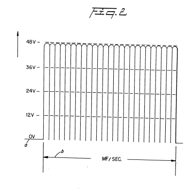 With reference to the graph of Figure 2, the direct current input voltage is a pulsed at a repetition rate, as shown by waveform b, (per second) equal to the frequency of the resonant cavity.
To enhance the forceful action of the applied pulsed direct current voltage/potential on the water molecule and the sub-atomic action for the release of gasses, the pulsing of the direct current is periodically interrupted as shown in the graph of Figure 2A.
That is, the pulse frequency and pulsed direct current c1, c2, is interrupted in uniform intervals d1, d2 and d3.
Again, the pulsed direct current may be aperiodically interrupted.
|
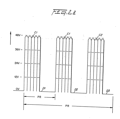 |
That is, the interruption between pulses c,c1,c2,c, c_1, c_2, and c3c_3 ... is for different time periods: e1,e2,e_1, e_2, and e3e_3.
Returning to Figure 1, an opening 8 is provided in the uppermost portion of the outer sphere 9 of the resonant cavity 3 structure.
The travel of the gas atoms 7 bombarding back and forth in the resonant cavity 3 will eventually pass through the opening 8.
However, the movement of the gas atoms 7 has been enhanced as aforesaid and when they pass through the opening 8 they are at an extremely high velocity.
That is, the motion of the gas atoms 7 will pass out of opening 8 as though they are jet propelled.
The structure of Figure 1 is that of a sphere 9 with another sphere 15 positioned therein.
The spacing between the outer surface of the inner sphere 15 to the inner wall 9a of sphere 9 provides a resonant cavity to a given frequency of the physical force of the direct current voltage.
Other resonant cavities may be utilized in other arrangements.
|
 |
In Figure 3 the resonant cavity structure 20 is utilized in a first completed self-contained embodiment.
Water 4 is entered via nozzle 19 directly into the chamber of the closed sphere 9.
The structure of Figure 3 is substantially identical in operation to that of Figure 1.
However, in this embodiment, the opening 8 and nozzle 2 size is of a controlled diameter.
The velocity of the gasses being expelled determines the port of the nozzle 2.
That is, the port in the nozzle 2 must be sufficiently large to permit an adequate amount of gas to be expelled to maintain a flame.
However, the port in the nozzle 2 must not be enlarged to wherein the velocity of the gasses expelled would be so great that combustion cannot be sustained.
The direction of the high velocity gasses is controlled by guide 13.
The gasses 7 may be ignited by igniter 25 or utilized directly in another manner.
The resonant cavities of Figures 1, 3, and 7 are related to the spacing between an outside and an inside spherical structure comprising a resonant cavity to the excited elements in a sub-atomic process.
Other configurations particularly those shown in the aforesaid co-pending patent application, may be constructed or modified to be resonant cavities.
The resonant cavities will enhance the release of the gasses in the sub-atomic action, irrespective of its configuration.
However, which structure is most productive may be related to its utilization in an operable embodiment.
|
|
 |
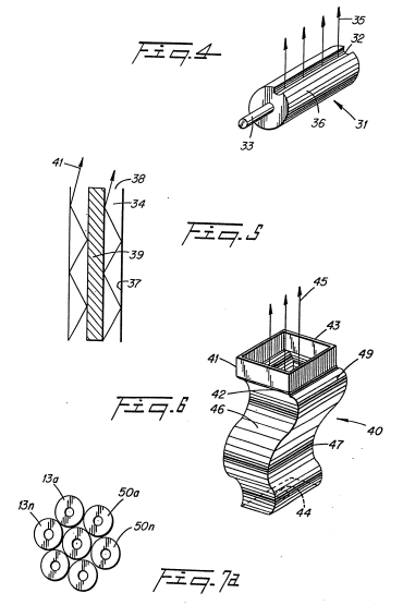 More particularly, the resonant cavity of Figure 4 is an elongated exciter 31. The spacing between the elements 33 and 36 provide the resonant cavity. The gasses 35 in this embodiment will be jettisoned broadside along the slot 32.
In Figure 5 there is illustrated the coaxial exciter arrangement of the preferred embodiment of the aforementioned co-pending patent application.
In this embodiment the spacing 34 between the inner plate 39 and the inner wall of the outer element 37 is adjusted to be resonant at a given frequency.
The input direct current is pulsed accordingly.
The gasses are propelled along the longitudinal axis of the elements 37 and 39 and expelled from the end 38 of the exciter.
The exciter 40 of Figure 6 is an improvement over the corrugated surface exciter disclosed in my co-pending patent application, Serial Number: 06/367/052.
In that exciter, the increased surface area provided by the corrugations and creating the resonant cavity, thus enhances the sub-atomic action.
In the embodiment of Figure 6, the corrugations provide an enhancement of the sub-atomic action, over that aforesaid, on the water entering at 44.
The spacing 46 between the plate 41 and 42 is such to be resonant at a particular frequency, as aforementioned.
However, instead of a forward direct line back-and-forth path of the atom flow, the corrugations of the convex 47 and concave 49 surfaces causes the atoms to move in forward and backward / back-and-forth path.
The increased movement; in turn, increases the sub-atomic action and the velocity of the flow of gasses 45 omitted from the end of 43 of the exciter 40.
Referring now to Figures 7 and 7A, the structure of Figure 1 is in an array of resonant cavities 50.
|
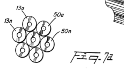 |
Specifically the housing 51 having a water 52 therein includes the array of exciters, having a positive potential applied to its central element 53, via terminal 64 and a negative potential to the outer element 55.
The direct current potential is pulsed in a repetitive frequency, as noted above, to match the frequency of the resonant cavity.
The gasses 54 being released from each of the exciters is directed by the guide walls 56 to the upper chamber 58 wherein the high velocity gasses 54 are accumulated.
As the gasses 54 are accumulated the pressure in the upper chamber 58 increases proportionally.
With reference to Figure 3, the port 2 is controlled in size of opening relative to the velocity of the gasses.
If the port 2 is oversized the velocity of the gasses will be so great that a flame could not be sustained and backfire may occur. Hence the port size is limited.
In Figure 7, the ports 57 may be greater in size than the individual port 2 of Figure 3.
|
|
The individual outputs are not utilized to support a flame hence the significance of limiting the port size and the danger of flashback is not critical.
The outputs from each of the exciters are accumulated as gasses 54 in a master chamber 58.
With particular reference now to Figure 8 there is illustrated an array of the gas exciters illustrated in Figure 3.
The operation of the individual gas exciters is identical to that of Figure 3 except that in the array the several gas flames from the individual exciters are accumulated in chamber 75.
Throughout the above specification the term "plate" is used to denote an element as described.
It is specifically understood that the term plate is not to be limited to a flat or planar construction, but may be a structure of any configuration.
Although certain embodiments are shown, modification may be had without departing from the spirit and scope of the invention.
CLAIMS:
-
A non-electrolysis process for separating hydrogen and oxygen gas from water, comprising:
- at least a pair of electrically conductive, non-oxidizing exciter elements, means for maintaining said pair of elements, spatially positioned for passing water therebetween,
- a source of direct current voltage potential having a positive and negative terminal, and means for connecting one of said exciter elements to said negative terminal and means for connecting the other of said exciter elements to said positive potential,
- said spatial position between said exciter elements defines a resonant cavity to a given wavelength, and
- means to pulse said direct current voltage potential repetitively at a frequency matching the wavelength of said resonant cavity.
-
A non-electrolysis process as set forth in Claim 1 wherein said exciter elements further comprise a sphere and a second sphere of substantially smaller size, and
- means for maintaining said smaller sphere centrally positioned within said other sphere,
- said spherical element includes a water inlet in the outer spherical element and another opening therein to permit the gasses to be expelled therefrom.
-
A non-electrolysis process as set forth in Claim 1 wherein said pairs of exciter elements are in an array of identical pairs of exciter elements.
-
A non-electrolysis process as set forth in Claim 3 wherein said exciter elements in an array of identical pairs of exciter elements, each further comprising a sphere and a second sphere of substantially smaller size, and
- means for maintaining said smaller sphere centrally positioned within said other sphere, and
- said means for accumulating the gaseous outputs from said array of exciter elements into a common chamber.
-
A non-electrolysis process as set forth in Claim 4 wherein said means for accumulating the gaseous outputs from said array of exciter elements into a common chamber, further comprises an igniter for igniting the accumulated gasses, and
- means for utilizing said ignited gasses, and
- wherein said means for utilizing said ignited gasses comprises a port size controlled nozzle.
-
A non-electrolysis process as set forth in Claim 1 wherein said exciter elements is in a coaxial arrangement,
- and, wherein the outside element comprises a longitudinal slot to provide a side projection output.
-
A non-electrolysis process as set forth in Claim 1 wherein said exciter elements are in a coaxial arrangement,
- and, wherein said coaxial arrangement is closed at one end and open at the other end to provide an end projection output.
-
A non-electrolysis process as set forth in Claim 1 wherein said exciter elements are flat plates, and
- wherein said plates have at least one open end.
-
A non-electrolysis process as set forth in Claim 1 wherein said exciter elements comprise non-planar plates.
-
A non-electrolysis process as set forth in Claim 9 wherein said non-planar plates comprise a series of corrugated surfaces and wherein said corrugated surfaces provide a back-and-forth reflective movement of said atoms.
-
A non-electrolysis process as set forth in Claim 2 further comprising igniter means for igniting the gasses therefrom.
-
A non-electrolysis process as set forth in Claim 3 wherein said array of identical pairs of exciter elements, each further comprising a sphere and a second sphere of substantially smaller size.
- means for maintaining each of said smaller spheres centrally positioned within said outer sphere,
- an igniter for igniting the output gasses from each of the outputs of said spherical elements.
- A non-electrolysis process as set forth in Claim 12 wherein said exciter elements further comprise a chamber for accumulating the output flames from each of said exciter elements,
- an output port for utilizing the combined flame outputs of said exciter elements.
- A non-electrolysis process as set forth in Claim 4 wherein the process comprises:
- a housing having said array of elements positioned therein, and
- means for maintaining said water in said housing above a predetermined level.
- A non-electrolysis process as set forth in Claim 12 further comprising:
- a source of water interconnecting each of said exciter elements for maintaining each of said exciter elements at a predetermined water level.
-
A non-electrolysis process as set forth in Claim 1 wherein said means to repetitively pulse said direct current voltage potential further comprises means to periodically interrupt said pulsing.
-
A non-electrolysis process as set forth in Claim 1 wherein said means to repetitively pulse said direct current voltage potential further comprises means to aperiodically interrupt said pulsing.
-
A non-electrolysis process as set forth in Claim 1 wherein said exciter elements are non-oxidizing.
|
|
|
|
|
|
|
|
|
|
|
|


EP0103656A3 Resonant Cavity for a Hydrogen Generator
Source: SMeyer-EP0103656A3-Resonant_Cavity_for_a_Hydrogen_Generator.pdf
EUROPEAN PATENT APPLICATION
- Application number: 82111598.7
- Date of filing: 14.12.82
- Priority: 24.09.82 US 422594
- Date of publication of application: 28.03.84 Bulletin 84/13
- Date of deferred publication of search report: 22.08.84
- Designated Contracting States: AT BE CH DE FR GB IT LU NL SE
Applicant: Meyer, Stanley A.
3792 Broadway
Grove City Ohio 43123 (US)Inventor: Meyer, Stanley A.
3792 Broadway
Grove City Ohio 43123 (US)Representative: Wassmeier, Alfons, Dipl.-Ing. et al
Postfach 382 Gräfingerstrasse 7
D-8400 Regensburg (DE)
Resonant cavity for a hydrogen generator.
 A direct current voltage exciter for utilization in a non-electrolysis process and apparatus for separating hydrogen-oxygen gas from water.
The non-oxidizing exciters comprise a plate structure with negative potential applied to one such exciter plate (9) and a positive potential applied to the other (15).
The spacing between plates comprises a resonant cavity (3) to a particular frequency.
The direct current voltage is pulsed at a repetition rate that matches the frequency of the resonant cavity (3).
The sub-atomic action of the direct current voltage on the plates is enhanced considerably by the bombardment of the atoms within the resonant structure.
A spherical plate construction is described with alternative structures of a resonant unit.
EP0106917A1 Gas Electrical Hydrogen Generator
Gas electrical hydrogen generator.
 A hydrogen gas generator system for converting water into hydrogen and oxygen gasses, in combination with a magnetic particle accelerator for voltage/current amplification.
The hydrogen gas generator encompasses an array of plates immersed in water in a pressure-tight enclosure.
Direct current voltage applied to the plates causes the hydrogen/oxygen gasses to disassociate from the water molecule.
The upper portion of the container is a hydrogen/oxygen collection chamber for maintaining a predetermined gas pressure. A hydrogen/oxygen gas mixture outlet means connected to the collection chamber of the generator includes a magnetic particle accelerator in magnetic relationship with the primary winding for imparting a magnetic potential to the hydrogen gas and the oxygen gas atoms as they are being pressure released from the collection chamber.
Attached to the gas outlet means is a non-magnetic conductive loop or tubing.
A coil wound around the tubing will have a voltage induced therein as the pressure velocity polarized magnetized gas particles pass therethrough.
The induced voltage is used as an electrical power source.
The hydrogen and oxygen gas may be utilized such as a burner system or alternatively returned to the gas storage area of the hydrogen generator in a closed-loop arrangement for recycling.
CROSS REFERENCE AND BACKGROUND:
There is disclosed in my co-pending patent application, filed, September 16, 1981, Serial Number, 302,807, for, Hydrogen Generator, a hydrogen gas generating system.
The apparatus comprises a pressure-tight enclosure for a water bath having immersed therein an array of plates.
The hydrogen and oxygen atoms are disassociated from the water molecule by the application of a non-regulated, non-filtered, low-power, direct current voltage potential to the plates having water passing therebetween.
The plates are non-oxidizing and of similar metal to comprise a sub-atomic action non-electrolysis system. The upper portion of the container is a hydrogen/oxygen storage chamber for maintaining a predetermined level.
In my co-pending patent application, Serial Number: 411,977, for, Controlled Hydrogen Gas Flame, filed, August 25, 1982, there is disclosed a hydrogen gas burner.
The nozzle in that burner is connected to the storage area or gas collection chamber via an appropriate line.
The port in the nozzle has an opening of a controlled size and configuration, related to the size of the flame and the temperature and velocity of the burning gas mixture.
Also, in my co-pending patent application, Serial Number 367,051, for Electrical Particle Generator, filed April 4, 1982, there is disclosed an electrical generating system.
The non-magnetic pipe is filled with the discrete gas particles having a magnetic polarized field placed thereon.
The magnetic charged gas particles proceed through the pipe at a high velocity dependent on the pressure in the gas generator storage chamber.
As the magnetic particles pass through the core of the winding there is induced a voltage/current therein, that may be utilized in the same manner as any other electrical source.
The hydrogen/oxygen gas mixture emitted from the opposite end of the pipe is connected to a gas burner where the hydrogen/oxygen gas mixture may be utilized such as for a flame as shown in my co-pending application, Serial number, 411,977.
When the flame is not in use the gas is directed back by alternate means to the storage chamber in the hydrogen generator in a closed loop arrangement.
SUMMARY OF INVENTION:
The present invention utilizes the basic principle of a particle accelerator and the principle of inducing a voltage current in a secondary winding by passing a magnetic element therethrough in combination with a hydrogen gas generator.
The particle accelerator utilizes the principles of my co-pending application, Serial Number, 367,051, and the hydrogen generator is particularly that of my co-pending patent application, 302,807.
The structure comprises an electrical inductive winding, having a large number of turns and an output for utilizing the voltage current induced therein. The inductive winding is positioned around an endless - closed loop, non-magnetic pipe or tubing.
The hydrogen gas generator encompasses an array of plates immersed in a pressure-tight enclosure.
Direct current voltage applied to the plates causes the hydrogen/oxygen gasses to disassociate from the water molecule.
The upper portion of the container is a hydrogen/oxygen storage chamber for maintaining a predetermined gas pressure.
A hydrogen/oxygen gas mixture outlet means connects the non-magnetic tubing to the storage chamber of the generator.
Adjacent the outlet a magnetic polarizer establishes a magnetic field and imparts a magnetic potential to the hydrogen and the oxygen gas being pressure released from the outlet.
The apparatus comprises a non-magnetic pipe in a closed loop having a substantial amount of magnetized particles encapsulated therein.
A magnetic accelerator assembly is positioned on the pipe and includes an inductive primary winding with a low voltage input.
A secondary winding is positioned on the pipe opposite to the primary winding.
Upon voltage being applied to the primary winding, the magnetized particles accelerate through the magnetic accelerator assembly with increased velocity.
The velocity-accelerated particles induce an electrical voltage/current potential as they pass through the secondary winding.
In a closed-loop system, the process is continuous.
The increased secondary voltage current is utilized in a direct current or alternate current amplifier arrangement.
OBJECTS:
It is a principal object of the present invention to provide a hydrogen gas electrical generator capable of producing a voltage/current much greater in magnitude heretofore possible.
Another object of the present invention is to provide such a hydrogen gas electrical generator utilizing magnetized elements and wherein the magnetized elements are charged gas particles from a hydrogen generator.
Another object of the present invention is to provide such a hydrogen gas electrical generator in combination with a controlled output hydrogen generator.
Another object of the present invention is to provide such an electrical generator that may be utilized with a hydrogen generator having another utility output for alternative generation.
A further object of the present invention is to provide such an electrical generator that utilizes components readily available and adaptable to the simplified embodiment.
Other objects and features of the present invention will become apparent from the following detailed description when taken in conjunction with the drawings in which:
BRIEF DESCRIPTION OF DRAWINGS
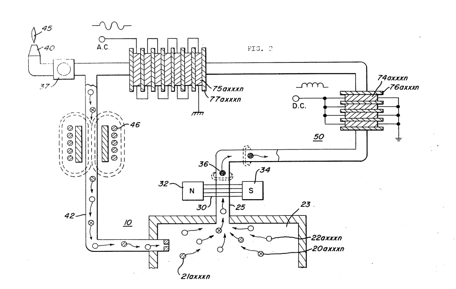
Figure 1 is a simplified illustration of the principles of the invention, in cross-section showing the particles voltage/current amplifier together with the hydrogen generator in a preferred embodiment.
Figure 2 is a magnetic particle tubing, in an electrical schematic circuit arrangement, illustrating the induced direct and alternating current voltage.
|
|
|
DETAILED DESCRIPTION OF DRAWINGS:
Referring now to Figure 1 there is illustrated the invention of the preferred embodiment in a simplified schematic arrangement.
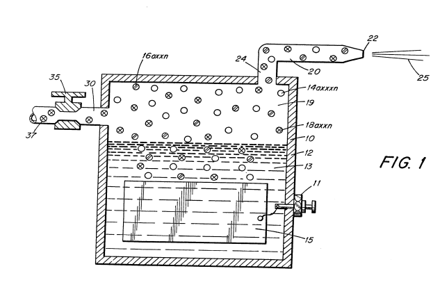
The generator 10 comprises an airtight pressure enclosure/housing 15.
The housing 15 is filled with water 12 to a predetermined level.
Immersed in the water 12 is an array of plates 14.
In the preferred embodiment of the invention of Figure 1, as disclosed in my co-pending application serial number 302,807. The plates 14 are in pairs of similar non-oxidizing metal.
A negative voltage current potential and a positive voltage current potential from source 16 is applied to alternate plates of the array 14.
The generation of hydrogen/oxygen is a sub-atomic process, i.e., not electrolysis.
That is, the applied potential to the plates causes the hydrogen and oxygen atoms to disassociate themselves from the water molecule.
Accordingly, the process is operative with any water irrespective of its purity or amount of contamination.
It is understood, of course, that the hydrogen generator may be that of the electrolysis process — although more costly and less efficient.
In that event the plates 14 would an anode and cathode and the water would be distilled water with a chemical added.
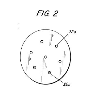
The released hydrogen gas depicted as particles 20a xxx n and oxygen gas particles 22a xxx n are collected and stored in the chamber 23 together with other released gases such as nitrogen 21a xxx.
The chamber 23 further includes switch means 57 to shut off the electrical source 16 to the generator system when the pressure in the chamber 23 sensed by pressure gauge, 55, achieves a predetermined level.
In the operation of the hydrogen generator as a burner, as disclosed in the co-pending patent application Serial Number 411,797, the outlet tube 25 is connected directly to the nozzle 40 to obtain the flame 45 upon ignition.
The operation of the gas burner is not altered in the present invention.
There is interposed in the line 25, a magnetic polarizer 30 having magnetic poles 32 and 34.
The magnetic polarizer 30 may be a permanent magnet or an electrical magnet capable of creating a magnetic field 36 across the non-magnetic tubing 25.
The magnetic field 36 in turn imparts a magnetic charge to the gases released from the storage chamber 33.
The hydrogen gas particles become positively magnetically charged and the oxygen particles become negatively magnetically charged — producing a magnetized gas mixture.
 Also interposed in the outlet tubing 25 adjacent to the magnetic polarizer 30 is a series of loops of non-magnetic tubing 50.
The tubing in its loop configuration can be any one of the arrangements illustrated in my co-pending patent application, serial number supra.
The opposite end 51 of the loop 60 tubing is connected via a Y connection either to the burner assembly 40, via line 35, or a return line 42 to the storage chamber 23.
As aforesaid, the storage chamber 23 is maintained at a predetermined pressure; and once the pressure is attained the gas particles will be expelled into outlet line 25 with a substantial velocity.
The pressure-released particles become charged by the magnetic polarizer 30 and pass through the entire loop arrangement of tubing 50.
The loop arrangement of tubing 50 has wound thereon a substantial number of turns 60a xxx n in a winding 60.
The number and size of the turns is related to the tubing configuration and voltage current output.
The magnetically charged gas particles traveling with a high-pressure velocity pass through the tubing 55.
As the magnetically charged gas particles pass through the core of the winding 60, there is induced a voltage current therein through its inductive field.
The output voltage current is utilized via terminals 70-72.
Upon demand for the flame, (such as for heat) from demand circuit 65, the valve 37 is opened causing the gas mixture to go to the nozzle 40 and provide the flame 45 upon ignition.
Upon satisfaction of the demand, the valve 37 will close and thereby cause the gas mixture to return to the collection chamber 23 via close loop line 42.
In this arrangement, the pump 45 will turn on and cause a continuous circulation of the gas through the closed loop. One-way check valve 49 assures that no gas enters line 42 when the pump 45 is quiescent.
If the gas in the collection chamber is of the preset pressure, as sensed at gauge 55, the voltage via terminal 16 will be cut off discontinuing the generation of gas.
With particular reference to Figure 2, there is illustrated, partly in schematic and partly pictorial, the preferred embodiment of the invention.
Initially, it is noted that the pump 45 of Figure 1 has been replaced by the particle accelerator 46.
The accelerator 46 is a non-mechanical/no moving part element and therefore not subject to wear.
It is to be recalled that the hydrogen and oxygen gases have placed there on a magnetic field potential.
Hence, as the magnetized gases approach the accelerator 46 they are attracted, and as they pass the center of the accelerator, they are propelled therethrough.
Other propulsion means in lieu of the pump 45 of Figure 1 or the accelerator 46 of Figure 2 may be utilized.
The volume of the hydrogen/oxygen gas as dictated by the storage area 23 and the pressure of the hydrogen/oxygen gas stored therein determines the magnetic field strength.
The greater the pressure, the greater the velocity; and, in turn, the greater the voltage/current output.
As noted in the aforesaid co-pending patent application, the induced current/voltage can be, at the output 70-72, either direct current, or alternating current, or both.
With reference to Figure 2, the simplified schematic illustrates a direct current voltage 4 parallel winding and an alternating current 75 in serial winding.
The number of coils 74a xxx n of direct current windings of coil 74 will determine the ripple frequency of the direct current voltage and its amplitude.
Similarly, the number of alternating current windings 75a xxx n will determine the alternating frequency of the alternating current voltage and its amplitude.
More importantly, the aforesaid ripple frequency of the single polarity voltage of coil 74 and alternating frequency of the alternating voltage of coil 75 can be altered, varied, and controlled.
That is, the frequency is a function of the number of discrete windings of the coils times the velocity of the gas per second.
The velocity of the gas, in turn, is varied by varying its magnetic field; and the magnetic field is varied by varying the pressure of the gasses in the chamber 23.
Further, it has been found that the increase in pressure of the gasses in chamber 23 increases the velocity of the gas exponentially.
Simply, an arithmetical increase in pressure of the gasses released results in a geometrical increase in frequency and amplitude of the output voltage from either the direct current winding 74 or the alternating current winding 75.
There will be instances where an increase in velocity (pressure) is needed to increase the output voltage of the electrical generator but the generation of more hydrogen gas may be undesirable.
That is, for instance, the flame 45 is a controlled gas mixture flame.
The addition of more hydrogen will increase the temperature of the combustibility of the mixture and will increase its velocity. The utility of the flame, if not quenched, will be affected proportionately.
Accordingly, to increase the gas pressure in chamber 23 other non-combustible gasses 21a xxx n, such as nitrogen are added via pressure inlet means to the mixture.
Although certain and specific embodiments are shown and described, alternatives and modifications may be had without departing from the spirit and scope of the invention.
CLAIMS:
- In combination, a hydrogen/oxygen electrical generator comprising:
-
a housing having a water reservoir for retaining natural water therein and a gas collection chamber maintaining a preset volume of gas under pressure,
-
a pair of similar non-oxidizing plates positioned in said water reservoir,
-
a direct current voltage source connected to said plates to cause a sub-atomic force-type action on said water,
said action disassociating the hydrogen atoms and oxygen atoms from said water molecules; and
-
a non-magnetic tubing for passing magnetic lines of force, connected at one end to said collection chamber via said outlet,
-
a magnetic polarizer positioned adjacent to said one end of said tubing for magnetically charging said hydrogen and oxygen gas atoms pressure expelled from said outlet,
-
an inductive winding positioned over said tubing; and
wherein the flux lines of said magnetized gas passing through said tubing and traversing said inductive winding induce a current/voltage in said inductive winding, and,
said winding having means for utilization of said induced voltage/current.
-
The combination of Claim 1 further comprising:
gas utilization means connected to the other end of said tubing for utilizing said generated hydrogen/oxygen gas mixture. -
The combination of Claim 1 further comprising:
a nozzle connected to the other end of said tubing, of a predetermined size and configuration, having a port for expelling said mixed gasses, and
means for igniting said gasses. -
The combination of Claim 1 further comprising:
control means for maintaining a predetermined gas pressure in said collection chamber. -
The combination of Claim 1 further comprising:
a pressure gauge for determining the pressure in said collection chamber, and
switch means connected to said direct current voltage source to terminate the generation of hydrogen/oxygen gasses upon said collection chamber attaining a predetermined pressure. -
The combination of Claim 1 further comprising:
a gas line tubing connected to the other end of said non-magnetic tubing and to said collection chamber in a closed loop arrangement. -
The combination of Claim 1 further comprising:
a gas line tubing connecting the other end of said non-magnetic tubing to said collection chamber in a closed loop arrangement, and
means in said gas line tubing for maintaining said polarized hydrogen and oxygen atoms circulating through said non-magnetic tubing. -
The combination of Claim 1 further comprising:
a gas line tubing connected to the other end of said non-magnetic tubing to said collection chamber in a closed loop arrangement, and
a unidirectional valve connected to the end of said gas line tubing connected to said collection chamber. -
The combination of Claim 1 further comprising:
a gas line tubing and gas utilization means,
a Y-type connector for alternately connecting said gas line tubing to said gas utilization means and said collection chamber in a closed loop arrangement. -
The combination of Claim 1 further comprising:
a gas line tubing and gas utilization means,
a Y-type connector for alternately connecting said gas line tubing to said gas utilization means said collection chamber in a closed loop arrangement,
two directional valve means, and
a demand circuit connected to said valve means for selectively connecting said gas line tubing to said gas utilization means or said collection chamber in response to pre-determined conditions. -
In combination, a gas electrical generator comprising:
a gas generator housing having a gas collection chamber for maintaining a preset volume of gas therein under pressure,
an outlet attached to said gas collection chamber,
a non-magnetic tubing connected to the opposite end of said outlet,
a magnetic polarizer positioned adjacent to said outlet between said chamber and said tubing for magnetically charging said gas pressure expelled from said outlet,
an inductive coil positioned over said non-magnetic tubing and wherein the flux lines of said magnetized gas passing through said tubing and traversing said inductive coil, induce a current/voltage therein,
means connected to said coil for utilization of said induced voltage/current. -
The gas electrical generator of Claim 11 wherein:
said gas is a combustible gas, and utilization means connected to the opposite end of said non-magnetic tubing for utilizing said gasses. -
The combination of a gas electrical generator as set forth in claim 11 wherein:
said coil comprises a plurality of windings wound in parallel, and wherein said induced voltage/current therein is of a single polarity. -
The combination of a gas electrical generator as set forth in Claim 11 wherein:
said coil comprises a plurality of windings wound in series, and wherein said induced voltage/current therein is of alternate polarities. -
The combination of a gas electrical generator as set forth in Claim 11 wherein:
said coil comprises a plurality of windings and wherein the number of said plurality of windings is determinative of the frequency of the said induced voltage/current therein. -
The combination of a gas electrical generator as set forth in Claim 11 further comprising:
means for varying the pressure of said gas in said collection chamber to vary the output frequency of said induced voltage in said coils. -
The combination of a gas electrical generator as set forth in Claim 11 further comprising:
means for varying the generation of said gas to vary the pressure of said gas in said collection chamber to vary the output frequency of said induced voltage in said coils. -
The combination of a gas electrical generator as set forth in Claim 11 further comprising:
means for adding non-combustible gases to said collection chamber to vary the pressure of said gas in said collection chamber to vary the output frequency of said induced voltage in said coils. -
The gas electrical generator of Claim 11 wherein:
said non-magnetic tubing further comprises means connected thereto for returning said magnetized gas to said collection chamber, and
means for recirculating said gas through said chamber, said non-magnetic tubing and said last named means. - The gas electrical generator of Claim 11 wherein:
said non-magnetic tubing further comprises means connected thereto for returning said magnetized gas to said collection chamber, a particle accelerator for recirculating said gas through said chamber, said tubing, and said last named means.
|
|
|
EP0111573A1 Hydrogen Generator System
EP0111574A1 Hydrogen Generator System
EP0111574B1 Hydrogen Generator System
EP0122472A2 Hydrogen Aeration Injection System
EP0122472A3 Hydrogen Generator System
EP0333854A4 Hydrogen Generator System
EP0381722A4 Hydrogen Aeration Injection System
WHAT IS CLAIMED IS:
-
A method of obtaining the release of a gas mixture including hydrogen and other dissolved gases entrapped in water, from water, consisting of:
- (A) providing a capacitor, in which the water is included as a dielectric between capacitor plates, in a resonant charging choke circuit that includes an inductance in series with the capacitor;
- (B) subjecting the capacitor to a pulsating, unipolar electric field in which the polarity does not pass beyond an arbitrary ground, whereby the water molecules within the capacitor are subjected to a charge of the same polarity;
- (C) further subjecting the water in said capacitor to said pulsating electric field to achieve a pulse frequency such that the pulsating electric field induces a resonance within the water molecule;
- (D) continuing the application of the pulsing frequency to the capacitor after resonance occurs so that the energy level within the molecule is increased in cascading incremental steps in proportion to the number of pulses;
- (E) maintaining the charge of said capacitor during the application of the pulsing field, whereby the co-valent electrical bonds of the hydrogen and oxygen atoms within said molecules is destabilized, such that the force of the electrical field applied within the molecule exceeds the bonding force of the molecule, and hydrogen and oxygen atoms are liberated from the molecule as elemental gases; and
- (F) collecting said hydrogen and oxygen gases, and any other gases that were formerly dissolved within the water and discharging said collected gases as a fuel gas mixture.
-
The method of claim 1 including the further steps of:
- (A) subjecting the collected gas mixture to a pulsating, polar electric field whereby electrons of the gas atoms are distended in their orbital fields by reason of their subjection to electrical polar forces, at a resonance with respect to an electron of the gas atom;
- (B) affecting said gas atoms with respect to their positive electrical field such that the energy level of the resident electron is increased in cascading incremental steps;
- (C) ionizing said gas atoms;
- (D) subjecting the ionized gas atoms to electromagnetic wave energy having a predetermined frequency to induce a further electron resonance in the ion, whereby the energy level of the electron is successively increased;
- (E) extracting further electrons from the resonating ions while said ions are in an increased energy state, releasing the nuclear and electron configuration of the atoms; and
- (F) subjecting the destabilized ions to thermal ignition, whereby thermal energy having a level enhanced over conventional combustion is achieved.
-
In an apparatus for obtaining the release of a gas mixture including hydrogen and other dissolved gases entrapped in water, from water, the improvement consisting of a resonant electronic circuit in operative relationship with the water in which the dielectric property of water determines the resonance of the circuit.
-
The apparatus of Claim 3, in which the resonant circuit includes a resonant charging choke.
-
The apparatus of Claim 3 or Claim 4 in which water is included as a dielectric between conductive plates that form a capacitor in the resonant circuit.
-
An apparatus in accordance with Claim 3 or Claim 4 or Claim 5 further including successively interconnected:
- (A) means for providing a pulsating, polar electric field to the gas mixture, whereby electrons of the gas atoms are distended in their orbital fields by reason of their subjection to electrical polar forces, at a frequency such that the pulsating electric field induces a resonance with respect to an electron of the gas atom; and the energy level of the resident electron is increased in cascading, incremental steps; and
- (B) means for providing a further electric field to ionize said gas atoms;
said further means connected to an electromagnetic wave energy source for subjecting the ionized gas atoms to wave energy of a predetermined frequency to induce a further electron resonance in the ion, whereby the energy level of the electron is further successively increased; and
- (C) an electron sink for extracting electrons from the resonating ions while such ions are in an increased energy state to destabilize the nuclear and electron configuration of said ions;
- (D) a control means for directing particle flow in a continuous manner through the electric fields, wave energy source and electron sink into a final stage at which the destabilized ions are thermally ignited; and
- (E) a thermal device at which the mixture of gases provided by the first means, after having passed through and been processed by the preceding means of the apparatus, is thermally ignited.
-
The method and apparatus as substantially described herein.
Full Patent List
SMeyer-EP0086439A1-Hydrogen_Gas_Injection_System_for_Internal_Combustion_Engine
SMeyer-EP0086439B1-Hydrogen_Gas_Injection_System_for_Internal_Combustion_Engine
SMeyer-EP0098897A2-Electrical_Generator_Utilizing_Magnetized_Particles
SMeyer-EP0098897A3-Electrical_Generator_Utilizing_Magnetized_Particles
SMeyer-EP0101761A2-Controlled_Hydrogen_Gas_Flame
SMeyer-EP0101761A3-Controlled_Hydrogen_Gas_Flame
SMeyer-EP0101761B1-Controlled_Hydrogen_Gas_Flame
SMeyer-EP0103656A2-Resonant_Cavity_for_a_Hydrogen_Generator
SMeyer-EP0103656A3-Resonant_Cavity_for_a_Hydrogen_Generator
SMeyer-EP0106917A1-Gas_Electrical_Hydrogen_Generator
SMeyer-EP0111573A1-Hydrogen_Generator_System
SMeyer-EP0111574A1-Hydrogen_Aeration_Injection_System
SMeyer-EP0111574B1-Hydrogen_Aeration_Injection_System
SMeyer-EP0122472A2-Hydrogen_Aeration_Injection_System
SMeyer-EP0122472A3-Hydrogen_Aeration_Injection_System