**PDF Download:** [SMeyer-EP0098897A2-Electrical\_Generator\_Utilizing\_Magnetized\_Particles.pdf](http://stanslegacy.com/attachments/12)
> European Patent Office > > Office européen des brevets > > Application number: 82711895.3 > > Date of filing: 14.12.82 0 098 897 A2 > > Publication number: EUROPEAN PATENT APPLICATION &) int.cl3: H 01 F 31/00 > > Priority: 09.04.82 US 367051 ® Date of publication of application: 25.01.84 Bulletin 84/4 > > Designated Contracting States: AT BE CH DE FR GB IT LI LU NL SE > > ® Applicant: Meyer, Stanley A. 3792 Broadway Grove City Ohio 43123(US) > @ Inventor: Meyer, Stanley A. 3792 Broadway Grove City Ohio 43123\[US) > > (3) Representative: Wasmeier, Alfons, Dipl.-Ing. et al, Postfach 382 Greflingerstrasse 7 D-8400 Regensburg{DE) ### Electrical generator utilizing magnetized particles > An electrical particle generator comprising a non-magnetic pipe in a closed loop having a substantial amount of magnetized particles encapsulated therein. A magnetic accelerator assembly positioned on said pipe having an inductive primary winding and a low voltage input to said winding. A secondary winding positioned on said pipe Opposite to said primary winding. Upon voltage being applied to said primary winding said magnetized particles are passed through said magnetic accelerator assembly with increased velocity. The velocity accelerated particles continuing through said pipe induce an electrical voltage/current potential as they pass through the secondary winding. The increased secondary voltage is utilized in an amplifier arrangement. #### Illustrations| [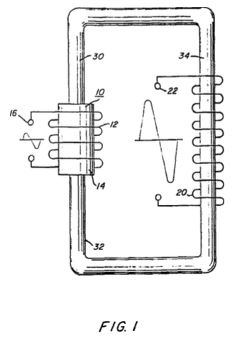](http://stanslegacy.com/uploads/images/gallery/2022-06/bR7TebMtLavDUcOT-image-1656427878606-51-15.png) | [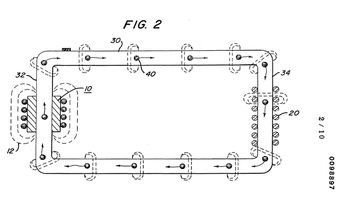](http://stanslegacy.com/uploads/images/gallery/2022-06/U3euUR8JlRjBe69q-image-1656427944605-52-22.png) | [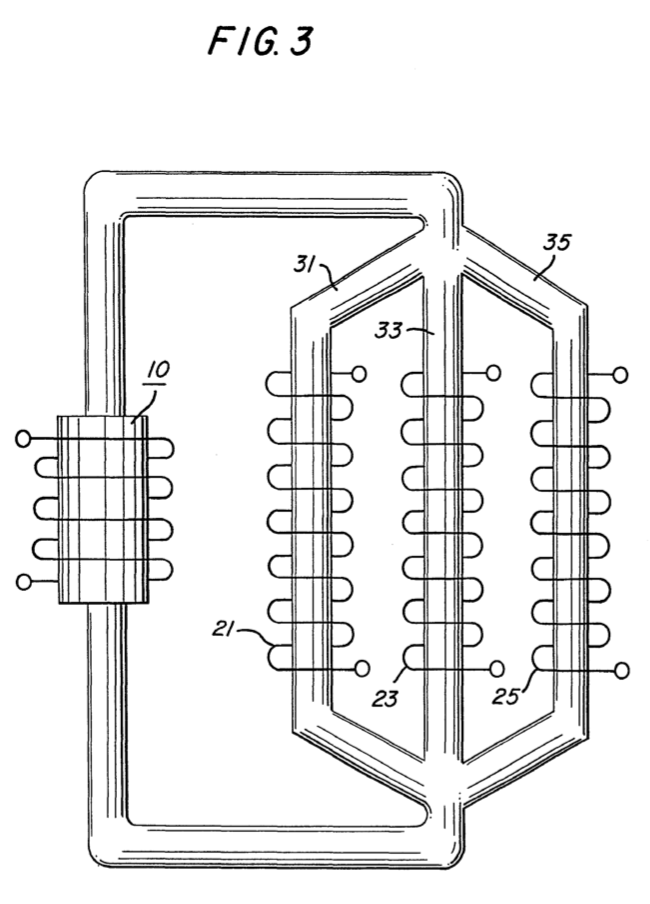](http://stanslegacy.com/uploads/images/gallery/2022-06/LqJ4VRZnqY1vVGE2-image-1656427952227-52-29.png) |
| [](http://stanslegacy.com/uploads/images/gallery/2022-06/08MUe0GdLxkbDuQz-image-1656427966313-52-44.png) | [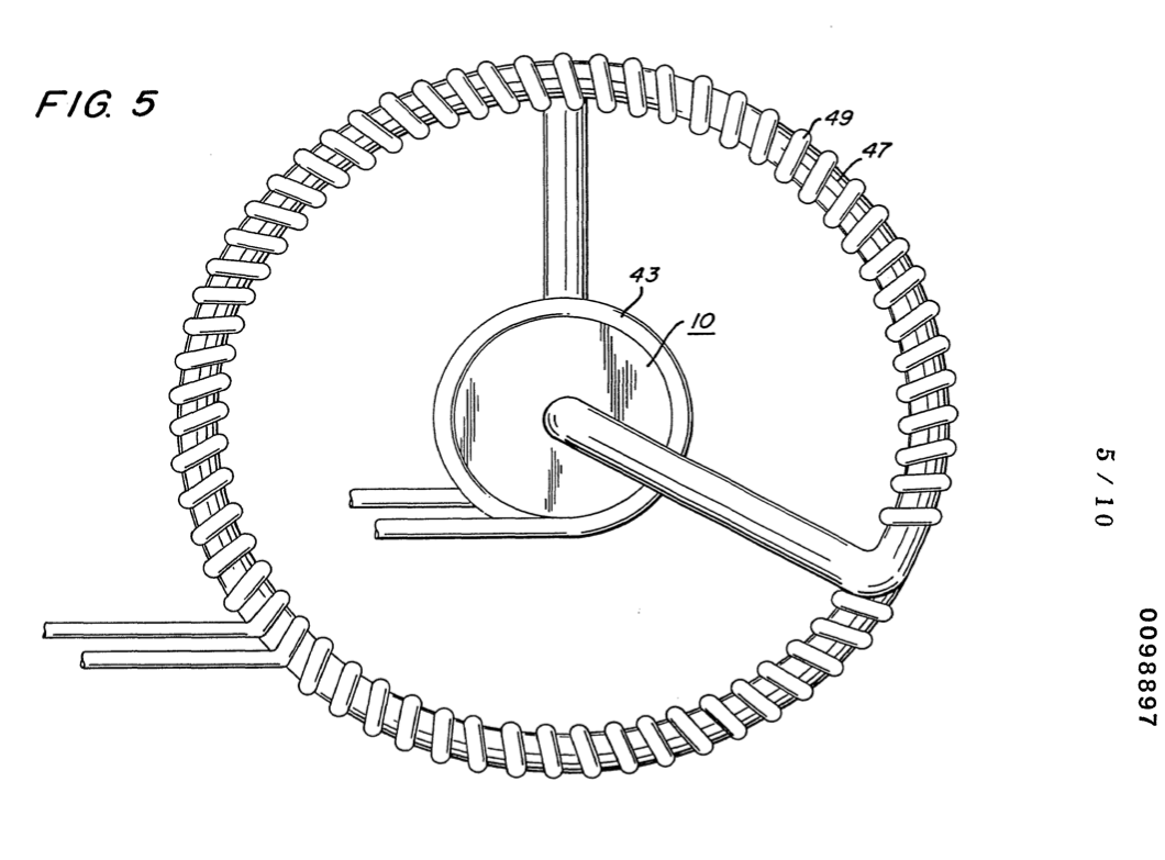](http://stanslegacy.com/uploads/images/gallery/2022-06/XxHsZFTxd3kUTX5d-image-1656427974319-52-52.png) | [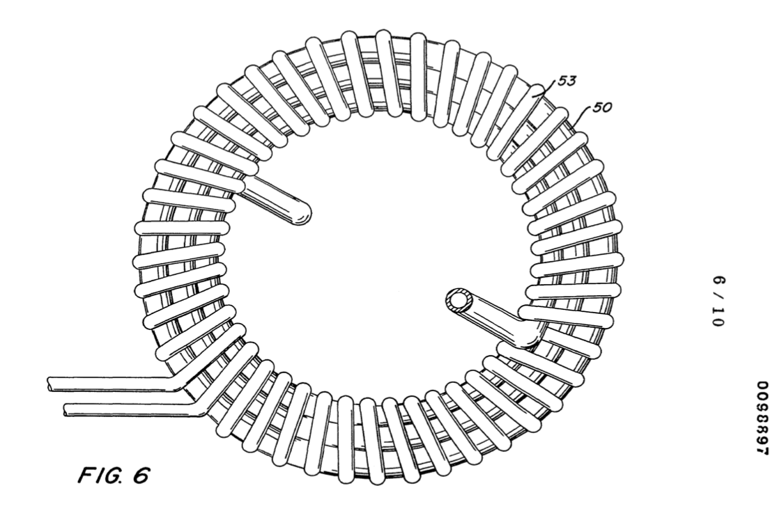](http://stanslegacy.com/uploads/images/gallery/2022-06/yxLIKRZdtumDxEHo-image-1656427998709-53-00.png) |
| [](http://stanslegacy.com/uploads/images/gallery/2022-06/JkhoEUxAAfqGhDRD-image-1656428007411-53-25.png) | [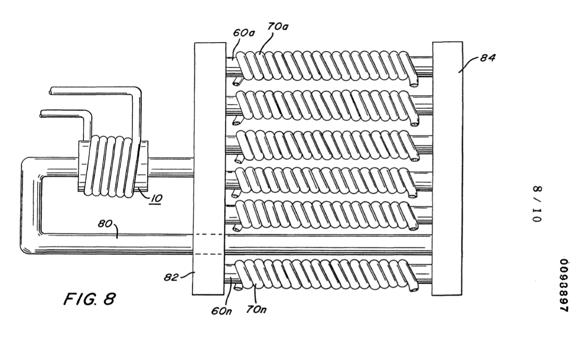](http://stanslegacy.com/uploads/images/gallery/2022-06/vCalk8O5N2OpH7M5-image-1656428013981-53-32.png) | [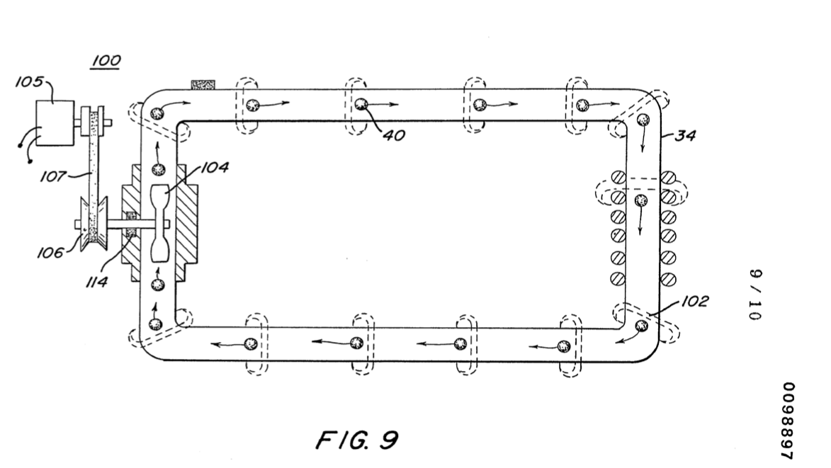](http://stanslegacy.com/uploads/images/gallery/2022-06/j3TUS0xABcUIueEH-image-1656428021462-53-39.png) |
| [](http://stanslegacy.com/uploads/images/gallery/2022-06/T38QpY7ePqqEs37Q-image-1656428033842-53-51.png) |
Other objects and features of the present invention will become apparent from the following detailed description where taken in conjunction with the drawings in which:
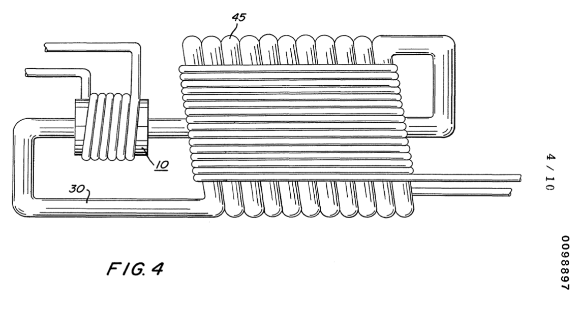
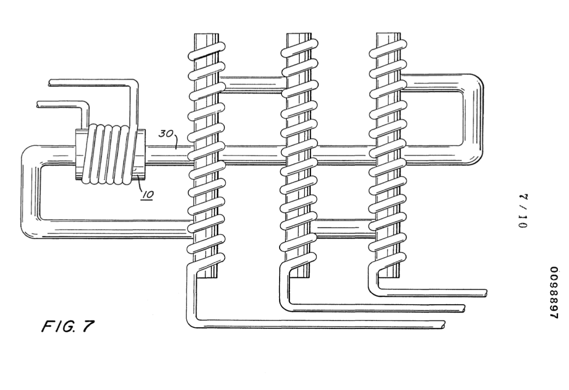
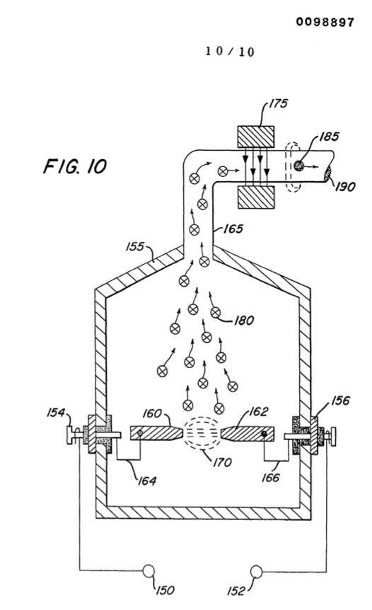
#### #### BRIEF DESCRIPTION OF DRAWINGS Figure 1 is a simplified illustration of the principles of the invention shown partly in crossection and partly pictorially. [](http://stanslegacy.com/uploads/images/gallery/2022-06/bR7TebMtLavDUcOT-image-1656427878606-51-15.png) Figure 2 is an electrical schematic illustration of the embodiment of Figure 1. [](http://stanslegacy.com/uploads/images/gallery/2022-06/U3euUR8JlRjBe69q-image-1656427944605-52-22.png) Figure 3 is an illustration similar to Figure 2 but adaptable to 3 phase. [](http://stanslegacy.com/uploads/images/gallery/2022-06/LqJ4VRZnqY1vVGE2-image-1656427952227-52-29.png) Figure 4 is a first alternative arrangement in a preferred illustration of the invention. [](http://stanslegacy.com/uploads/images/gallery/2022-06/08MUe0GdLxkbDuQz-image-1656427966313-52-44.png) Figure 5 is another alternative arrangement in a preferred illustration of the invention. [](http://stanslegacy.com/uploads/images/gallery/2022-06/XxHsZFTxd3kUTX5d-image-1656427974319-52-52.png) Figure 6 is another alternative arrangement in a preferred illustration of the invention. [](http://stanslegacy.com/uploads/images/gallery/2022-06/yxLIKRZdtumDxEHo-image-1656427998709-53-00.png) Figure 7 is another alternative arrangement in a preferred illustration of the invention. [](http://stanslegacy.com/uploads/images/gallery/2022-06/JkhoEUxAAfqGhDRD-image-1656428007411-53-25.png) Figure 8 is another alternative arrangement in a preferred illustration of the invention. [](http://stanslegacy.com/uploads/images/gallery/2022-06/vCalk8O5N2OpH7M5-image-1656428013981-53-32.png) Figure 9 is an alternative arrangement for a magnetic drive accelerator assembly. [](http://stanslegacy.com/uploads/images/gallery/2022-06/j3TUS0xABcUIueEH-image-1656428021462-53-39.png) Figure 10 is a mechanical illustration of a magnetic particle generator for developing magnetic particles utilized in the present invention. [](http://stanslegacy.com/uploads/images/gallery/2022-06/T38QpY7ePqqEs37Q-image-1656428033842-53-51.png) #### DETAILED DESCRIPTION OF INVENTIONWith particular reference to Figures 1 and 2 there is illustrated the invention in its mostly simplified schematic embodiment.
| [](http://stanslegacy.com/uploads/images/gallery/2022-06/bR7TebMtLavDUcOT-image-1656427878606-51-15.png) | [](http://stanslegacy.com/uploads/images/gallery/2022-06/U3euUR8JlRjBe69q-image-1656427944605-52-22.png) |
| [](http://stanslegacy.com/uploads/images/gallery/2022-06/XxHsZFTxd3kUTX5d-image-1656427974319-52-52.png) | [](http://stanslegacy.com/uploads/images/gallery/2022-06/yxLIKRZdtumDxEHo-image-1656427998709-53-00.png) |
Again, the pipe 30 is described as a **non-magnetic pipe**. There are certain non-magnetic pipes that would not be operable in the present invention. That is, the pipe 30 must be capable of passing magnetic lines of force; and that it is these magnetic lines of force that traverse the inductive field of the secondary windings 20 to induce a voltage/current therein.
A significant feature of the invention illustrated in the various embodiments hereintofore described, as the generation of the magnetized particles encapsulated in the tubing. With reference to Figure 10, there is illustrated apparatus for carrying out the process of vaporizing material into vaporized particles and thereafter magnetizing the particles by subjecting them to a magnetic field. The chamber 155 is a vacuated chamber haying positioned in its lower half portion a pair of electrodes 160 and 162 of magnetizable material. A source of voltage 150 and 152 provides voltage and current of opposite polarity via terminals 154 and 156 to the electrodes 160 and 162 via wire connections 164 and 166. The area 161 between the end of the electrodes 160 and 162 is the spark gap. Upon the application of power to the magnetizable material electrodes 160 and 162 the tip of the electrodes in the spark gap will be vaporized into particles 180. The particles 180 rise, use and enter into non-magnetic pipe 165. As the particles progress in movement they pass between the magnetic field generator 175. The particles each take on a magnetic charge as magnetized particles 185 and there- after are discharged via port 190 to the electrical particle generator above described. In the simplified preferred embodiment of Figures 1 and 2, as well as the referred preferred embodiments it was indicated that a low voltage was applied to the particle accelerator 10. Upon acceleration a high voltage/current would be induced in the secondary pickup coil 20. A most significant advantage of the present invention is that the voltage amplification is irrespective to the wave-shape of the input voltage. Specifically, if the input voltage is direct current a direct current voltage will be at the output; an alternating voltage will result in an alternating voltage at the output; a pulsed voltage will result in a pulsed voltage at the output; and a voltage of any other configuration will result in a similar configuration at the output. Although certain embodiments have been shown it is to be understood modifications may be had without departing from the spirit and scope of the invention.| [](http://stanslegacy.com/uploads/images/gallery/2022-06/bR7TebMtLavDUcOT-image-1656427878606-51-15.png) | [](http://stanslegacy.com/uploads/images/gallery/2022-06/U3euUR8JlRjBe69q-image-1656427944605-52-22.png) |
**Source: [SMeyer-EP0098897A3-Electrical\_Generator\_Utilizing\_Magnetized\_Particles.pdf](https://stanslegacy.com/attachments/277)**
#### **Electrical generator utilizing magnetized particles** [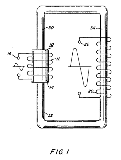](https://stanslegacy.com/uploads/images/gallery/2024-10/13ztUHXSiZ8nIoSp-image-1730146927008.png)An electrical particle generator comprising a **non-magnetic pipe** (30) in a closed loop having a substantial amount of **magnetized particles** (40) encapsulated therein. A **magnetic accelerator assembly** (10) positioned on said pipe having an inductive **primary winding** (12) and a low voltage input to said winding. A **second winding** (20) positioned on said pipe opposite to said primary winding. Upon voltage being applied to said primary winding said magnetized particles are passed through said magnetic accelerator assembly with increased velocity. The velocity-accelerated particles continuing through said pipe induce an electrical voltage-current potential as they pass through the secondary winding.The increased secondary voltage is utilized in an amplifier arrangement.
# EP0101761A2 Controlled Hydrogen Gas Flame > **Europäisches Patentamt** > **European Patent Office** > **Office européen des brevets** > > **Publication number:** 0 101 761 A2 > > Source: [SMeyer-EP0101761A2-Controlled\_Hydrogen\_Gas\_Flame.pdf](https://stanslegacy.com/attachments/13) > > --- > > ##### EUROPEAN PATENT APPLICATION > > 1. **Application number:** 82111597.9 > 2. **Date of filing:** 14.12.82 > 3. **Priority:** 25.08.82 US 411977 > 4. **Date of publication of application:** 07.03.84 Bulletin 84/10 > 5. **Designated Contracting States:** AT BE CH DE FR GB IT LU NL SE > > --- > > 6. **Applicant:** Meyer, Stanley A. > 3792 Broadway > Grove City Ohio 43123 (US) > 7. **Inventor:** Meyer, Stanley A. > 3792 Broadway > Grove City Ohio 43123 (US) > 8. **Representative:** Wassmiller, Alfons, Dipl.-Ing. et al. > Postfach 322 Gräfingerstrasse 7 > D-8400 Regensburg (DE) ##### **(54) Controlled hydrogen gas flame.** (A) A sustained controllable gas flame. The hydrogen generator utilized is that for separating gasses from water having impurities and other gasses entrapped therein. The gasses separated from the water comprises hydrogen, oxygen, and the non-combustible gasses, such as nitrogen. The nitrogen, oxygen, and hydrogen are mixed as they are released in the process by the generator and collected as the mixture of gasses in the collection chamber of the generator. The method and system comprises a nozzle of a given configuration connected through a line to the uppermost region of the gas collection chamber of the hydrogen generator. The nitrogen reduces the velocity and temperature of the burning flame from that of the hydrogen/oxygen mixture.To further control the temperature and velocity of the burning gas mixture there is added to the collection chamber other non-burnable gasses.
The configuration of the nozzle and its port opening is dependent on the mixture of gasses utilized and restricted thereby.An increase in the size of the flame requires additional port openings to prevent blowout.
**CROSS REFERENCE:** > The hydrogen/oxygen generator utilized in the present invention is that disclosed and claimed in my co-pending U.S. patent application, Serial Number: 302,807, filed: September 16, 1981, for: HYDROGEN GENERATOR SYSTEM. In that process for separating hydrogen and oxygen atoms from water having impurities, the water is passed between two plates of similar non-oxidizing metal. No electrolyte is added to the water. The one plate has placed thereon a positive potential and the other a negative potential from a very low amperage direct-current power source. The sub-atomic action of the direct current voltage on the non-electrolytic water causes the hydrogen and oxygen atoms to be separated — and similarly other gasses entrapped in the water such as nitrogen.The contaminants in the water that are not released are forced to disassociate themselves and may be collected or utilized and disposed of in a known manner.
The **direct current** acts as a **static force** on the water molecules; whereas the **non-regulated rippling direct current** acts as a **dynamic force**. Pulsating the direct current further enhances the release of the hydrogen and oxygen atoms from the water molecules.
| [](https://stanslegacy.com/uploads/images/gallery/2024-10/A17g4WnZQt53Wz9C-image-1730142905808.png) | [](https://stanslegacy.com/uploads/images/gallery/2024-10/2B9wW0EnqlFcR4Zc-image-1730142932913.png) |
However, in that the burning velocity of hydrogen is 265-325 cm./sec. versus 37-45 cm./sec. of that of gasoline, the velocity of hydrogen is so great that the hydrogen ensuing from a nozzle will not under ordinary circumstances sustain a flame.
Therefore, to sustain a flame at a nozzle attached to a hydrogen generator the burning velocity of the hydrogen gas must be reduced. It has been found that all water in its natural state, whether it be tap water, well water, sea water, or fresh water, is a saturation of ambient air. Further, in that ambient air contains a substantial amount of nitrogen, all natural water will have entrapped therein nitrogen.Again, the percentage of nitrogen entrapped in natural water has been determined to be a fixed percentage and very uniform at seventeen (17%) percent --- irrespective of the source of the water or its impurities.
Hence, a natural water gas analysis will show a seventeen percent of nitrogen relative to the hydrogen and oxygen. The nozzle connected to the collection chamber via an appropriate line has a port opening of a controlled size and configuration, related to the size of the flame and the temperature and velocity of the burning gas mixture.To maintain the flame, that is to prevent blowout, additional nozzles are included when the overall flame size is to be increased.
#### OBJECTS: - It is accordingly a principal object of the present invention to provide a new and improved hydrogen/oxygen generator that is operable from a water source that provides hydrogen/oxygen output that will have a sustained burn. - Another object of the present invention is to provide a hydrogen/oxygen generator that in addition to the hydrogen and oxygen gasses releases non-combustible nitrogen gas capable of reducing the burning velocity and temperature of a pure hydrogen/oxygen flame. - A further object of the present invention is to provide a hydrogen generator that includes the controlled addition of other non-combustible gasses to the gas chamber thereof to thereby further control the burning velocity and temperature of the hydrogen gas.Other objects and features of the present invention will become apparent from a reading of the detailed description of the preferred embodiment taken in conjunction with the single figure drawings in which:
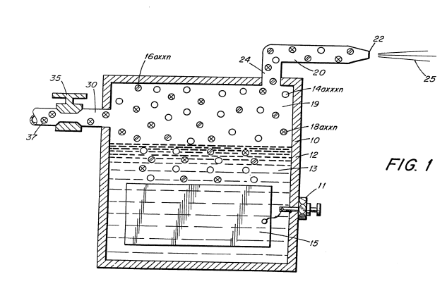
#### BRIEF DESCRIPTION OF THE DRAWINGS: - **Figure 1** is a cross-section of a hydrogen generator illustrating the features of the present invention in its most preferred embodiment incorporated therein. - **Figure 2** schematically shows the increased number of nozzle ports to increase the flame size.| [](https://stanslegacy.com/uploads/images/gallery/2024-10/A17g4WnZQt53Wz9C-image-1730142905808.png) | [](https://stanslegacy.com/uploads/images/gallery/2024-10/2B9wW0EnqlFcR4Zc-image-1730142932913.png) |
Water as an absorber of ambient air will entrap seventeen percent (17%) of **nitrogen gas**; that is, natural water absorbs seventeen percent (17%) of **nitrogen gas** in comparison to its hydrogen and oxygen gas content.
In operation of the hydrogen generator, in that it is a subatomic or force-type of generator, the gasses in the water will be released.Therefore, when natural water is used the nitrogen gas will be released together with the hydrogen and oxygen gasses.
In the preferred embodiment utilizing tap water, the nitrogen gasses 16 are intermixed with the hydrogen gasses 14 and the oxygen gasses 18 in the chamber 19 of the hydrogen generator 10. Upon release of the gasses via line 24 and nozzle 20 and then port 22 the gas mixture is ignited to provide flame 25. The flame 25 is sustained in that the nitrogen gasses 16 reduce the burning velocity and temperature of the hydrogen gas 14. A realistic and practical manner of further controlling the burning velocity and temperature of the hydrogen gasses 14 is by adding non-combustible gasses directly to the hydrogen and oxygen gasses generated. This is accomplished by inlet 30 to the upper gas chamber 19 of the hydrogen generator. Valve means 35 is adjustable to control the amount of non-combustible gasses added to the gas chamber. The nozzle 20 connected to the chamber 19 of the generator 10 via line 17, is of a given configuration to permit a predetermined quantity of gasses to be expelled from the port 22. The port size is dependent on the gasses generated, and collected in the chamber 19, the pressure of the chamber 19 of the generator 10, and the size of the flame desired. To increase the size of the flame 25 would appear to be a simple matter of increasing the rate of gasses generated. However, an increase of gasses merely causes a blowout at the port 22 opening of the nozzle 20. This flame blowout will occur since an increase in hydrogen gas generation disrupts the ratio of the initial mixture, even though the percentages remain constant. Typically, tap water will contain 62% hydrogen, 31% oxygen, and 17% nitrogen. In actuality, the percentages may be somewhat less dependent on other gasses that may be trapped in the tap water. The increase in production will not affect the percentages, but it must be appreciated that the volume of the gasses will be proportionately increased. In turn, the volume being directly related to pressure, the pressure will be similarly increased. To effectively reduce or counter the velocity due to the increased pressure of the hydrogen gas mixture in the chamber 19, a larger port 22 would appear to be capable of handling the increased pressure. But, as aforesaid, a larger port end and the concentration of the high velocity hydrogen gas mixture will cause a flame blowout. To sustain a larger flame with increased pressure, additional nozzles having ports or a nozzle 20 with multiple ports as shown in Figure 2, of a port size predetermined as aforesaid, will be added to the line 17. Accordingly, the larger the desired flame, the greater the number of ports. It can be understood that a port that will not sustain a flame does present a safety factor relative to hydrogen spark back to the chamber 19. Hence, controlling the size of the port 22 in effect acts as a quencher of hydrogen spark back. Although certain and specific embodiments are shown and described it is within the scope and spirit of the present invention to include alternatives and modifications thereto. --- #### **CLAIMS:** 1. A hydrogen/oxygen generator capable of sustaining the controlled burning of the gasses generated thereby comprising: - a housing having natural water therein including entrapped non-combustible gasses, - a pair of similar non-oxidizing plates having direct current low amperage voltage applied thereto to provide a sub-atomic, force-type action on said water, - said action liberating the hydrogen atoms and oxygen atoms from said water molecule, and further liberating said non-combustible gasses from said water, - a gas collection chamber in said generator for collecting and intermixing said released gasses, - a nozzle attached to the gas collection chamber of said housing including an inlet for receiving the mixture of hydrogen, oxygen and non-combustible gas, - said nozzle of a predetermined size and configuration on a port for expelling said mixed gasses, and means for igniting said mixed gasses. 2. The hydrogen/oxygen generator of Claim 1 wherein said non-combustible gas is nitrogen. 3. The hydrogen/oxygen generator of Claim 2 wherein said gasses intermixed in said collection chamber of the hydrogen generator comprise 62% hydrogen, 31% oxygen, and 17% nitrogen. 4. The hydrogen/oxygen generator of Claim 3 wherein said means comprises an inlet connected to said gas collection chamber of said housing, and means for introducing non-combustible gasses to said chamber. 5. The hydrogen/oxygen generator of Claim 4 wherein said inlet further comprises valve means for controlling the amount of non-combustible gasses introduced to said chamber. 6. The hydrogen/oxygen generator of Claim 5 wherein said port on said nozzle of a predetermined size and configuration is related to the ratio of gasses in said collection chamber to provide a flame of a predetermined velocity and size at said port. 7. The hydrogen/oxygen generator of Claim 6 wherein said port size and configuration is maintained with a plurality of ports to thereby permit a proportional increase in flame size. [](https://stanslegacy.com/uploads/images/gallery/2024-10/A17g4WnZQt53Wz9C-image-1730142905808.png) # EP0101761A3 Controlled Hydrogen Gas Flame # EP0101761B1 Controlled Hydrogen Gas Flame # EP0103656A2 Resonant Cavity for a Hydrogen Generator > Source: [SMeyer-EP0103656A2-Resonant\_Cavity\_for\_a\_Hydrogen\_Generator.pdf](https://stanslegacy.com/attachments/14) > > **Europäisches Patentamt** > **European Patent Office** > **Office européen des brevets** > > **Publication number:** 0 103 656 A2 > > --- > > ##### EUROPEAN PATENT APPLICATION > > 1. **Application number:** 82111598.7 > 2. **Date of filing:** 14.12.82 > 3. **Priority:** 21.09.82 > 4. **Date of publication of application:** 28.03.84 Bulletin 84/13 > 5. **Designated Contracting States:** AT BE CH DE FR GB IT LU NL SE > > --- > > 6. **Applicant:** Meyer, Stanley A. > 3792 Broadway > Grove City Ohio 43123 (US) > 7. **Inventor:** Meyer, Stanley A. > 3792 Broadway > Grove City Ohio 43123 (US) > 8. **Representative:** Wassmiller, Alfons, Dipl.-Ing. et al. > Postfach 322 Gräfingerstrasse 7 > D-8400 Regensburg (DE) --- ### Resonant cavity for a hydrogen generator A direct current voltage exciter for utilization in a non-electrolysis process and apparatus for separating hydrogen/oxygen gas from water. The non-oxidizing exciter comprises a plate structure with positive potential applied to one such plate and a negative potential applied to the other plate.The **frequency** between direct current pulses applied to the plate structure determines the frequency of gas liberation, and the **amplitude** of the direct current pulses determines gas generation considerably by the sub-atomic action on the resonant structure.
A structure of a resonant unit is described with alternative embodiments of this invention. > In my co-pending patent application, supra, it was shown the hydrogen gas generator is variably increased by varying the construction of the exciters; more particularly, by (1) increasing the area of the plates, (2) reducing the space between the plates, and (3) altering the physical configuration of the plate. ### SUMMARY OF INVENTION: The basic structure of and principals of operation of the aforesaid co-pending patent application are utilized. The non-oxidizing exciters are of a construction, **spherical** in a preferred embodiment, with a given spacing between the positive and negative elements to form a resonant cavity at a given frequency.The direct current voltage is pulsed at a repetition rate (frequency) to match the resonant wavelength.
At the matched frequency, the sub-atomic action of the pulsed direct current voltage is enhanced considerably.
The forceful action on the water molecule causes the molecules to be bombarded and break into its atomic structure at a much more rapid rate; thereafter, the gas atoms are set into motion within the resonant cavity, thereby increasing velocity to a jet-like action as they are released from a port.
The complete resonant cavity has a controlled size port for the release of the high velocity gasses. The resonant cavity plate structure in a preferred arrangement is an array of elements. The gasses emitted from the array are combined and expelled as high velocity gasses from a common nozzle and utilized. ### OBJECTS: It is a principal object of the present invention to provide an improved structure that enhances the separation of hydrogen/oxygen gasses from water. A further object of the present invention is to provide such a structure that enhances the sub-atomic action in a non-electrolysis process. Another object of the present invention is to provide such a structure wherein the sub-atomic action is controlled. Another object of the present invention is to provide such a structure wherein the velocity of the gasses released by a sub-atomic action are increased considerably. Other objects and features of the present invention will become apparent from a detailed description of the invention when taken in conjunction with the drawings in which: ### BRIEF DESCRIPTION OF DRAWINGS: - **Figure 1** is a schematic illustration of the structure of the present invention in its most simplified arrangement. - **Figures 2, 2A, and 2B** are a series of waveforms illustrating the pulse rate of the direct current to match the resonant frequency of the structure of Figure 1. - **Figure 3** is a schematic illustration of the utilization of the structure of Figure 1. - **Figure 4** is a first alternative structure to that shown in Figure 1. - **Figure 5** is another alternative structure to that shown in Figure 1. - **Figure 6** is another alternative structure to that shown in Figure 1. - **Figures 7 and 7A** are an array of exciters, such as shown in Figure 1, in a preferred embodiment. - **Figure 8** is an array of exciters, such as shown in Figure 3, in a preferred embodiment. ### DETAILED DESCRIPTION OF INVENTION: [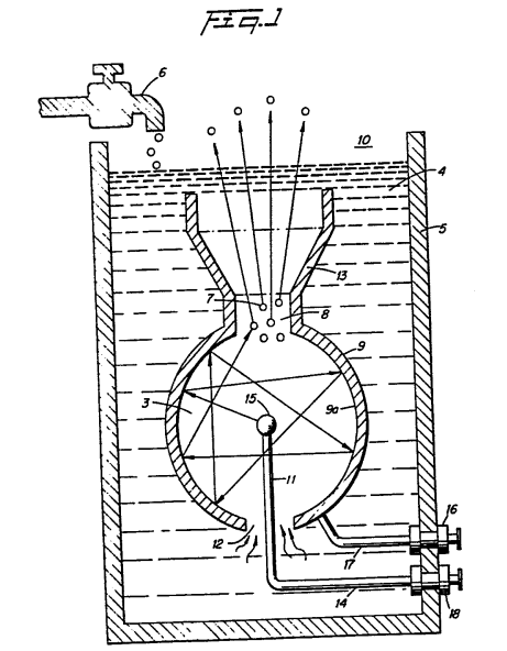](https://stanslegacy.com/uploads/images/gallery/2024-10/uJc1KoWTbR6GG7bM-image-1730143685782.png)Reference is now made to the several figures depicting the preferred embodiment of the present invention. With particular reference now to Figure 1, illustrating the mechanical schematic in a most simplified form of the invention, the housing 10 is a sphere having a gas expulsion opening 8 in its uppermost region, and a gas guide 13 flared out from the opening 8. Centrally positioned within the sphere 10 is another sphere 15 of much smaller diameter.The outer shell 9 of the sphere is the grounded negative side.
That is, the negative side of a direct current potential is applied via terminal 16 to the outer shell 9. To the inner element 15, the direct current positive potential is applied thereto via terminal wire 18 extended through a support element 11 entering the housing shell 9 through water intake opening 12. The negative potential via terminal 18 is connected to the sphere 9 via terminal 16 and wire 17. The vessel/housing 5 contains water 4, replenished by faucet 6, at a level above the entire structure. The water 4 is drawn into the outer sphere 9 through the lower opening 12. As described in my aforesaid patent application the direct current electrical potential is in the nature of a physical force on the water molecule. The sub-atomic action causes the water molecule to break up into its atomic structure -- two parts hydrogen and one part oxygen gas will be liberated from the water. Also other gasses, such as nitrogen, that may be entrapped therein will be released. In that the aforesaid process is not an electrolysis process, water of any origin may be used, irrespective of the contaminant content. In the process, as the gasses are released the contaminants will be separated and fall to the bottom of the container. Again, since the process does not in fact generate hydrogen but simply releases the hydrogen, the process is most efficient. The hydrogen released is much greater than the energy expended.Accordingly, the direct current voltage/potential is of extremely low voltage and only of an insignificant current.
> There is described in the process of my co-pending patent application apparatus and methods for increasing the output of hydrogen for a given voltage/potential input.For instance, plate spacing and plate area are discussed; pulsing the direct current and applying an unfiltered direct current all in one manner or another enhances the release of hydrogen.
Increasing the voltage/potential will increase the gas output proportionally. In each of the apparatus or methods for increasing the output, the physical force applied to the water molecule is the controlling factor. It can be appreciated that limitations may be reached in the control of these dynamic and static forces.In the present invention, the preferred embodiment utilizes in one manner or another, all of the aforementioned output control factors and is directed primarily to pulsing the direct current potential.
It has been found that the distance between plates of the exciters will have, or can be adjusted to have, a wavelength or partial wavelength, or a multiple wavelength, related to the motion of the water molecule in traveling from the one plate to the other.
Therefore, the structure is constructed to be a resonant cavity at some given frequency of the molecular motion.
[](https://stanslegacy.com/uploads/images/gallery/2024-10/uJc1KoWTbR6GG7bM-image-1730143685782.png)With specific reference again to Figure 1, the distance from the outer surface of the central element 15 to the inner surface 9a of the outer spherical element 9 will be at some wavelength to the molecular motion of travel. When the wavelength is matched with a physical force equal in frequency to that wavelength the inner area becomes a resonant cavity and the water molecule will forcefully be driven repetitively. > As understood in resonant cavities of an electron nature, the molecules are set into motion and will bombard back and forth from the one surface to the next continuously so long as the initial force is applied.In the sphere of Figure 1, the direction that the water molecules may travel from the inner sphere 15 to the surface 9a of the outer sphere 9 is of an infinite number.
Considering a single molecule, the water molecule's motion will under normal conditions be impeded by the water.If the distance between the inner and outer spheres is of a wavelength related to the frequency of the pulsating direct current applied to the water, the water molecule will be set in motion and thereafter enhanced in motion in the resonant cavity and exceed the impediment of water.
Further, the molecule upon striking the inside surface of the outer sphere, will be reflected and directed to an angular surface where it again will be reflected. This action continues indefinitely and will continue until the applied energy is terminated. Thus, a resonant cavity causes the water molecule to travel back and forth continuously and at a velocity that increases geometrically.The above-noted single molecule motion of travel will be further increased in velocity when it is considered that the number of water molecules is infinite and the striking force is not only from surface-to-surface but also from molecule-to-molecule.
The enhanced physical action on the water molecule in the resonant cavity will directly affect the breaking up of the molecule into its gaseous atomic structure. As this occurs the hydrogen, oxygen, and other gasses that may be released from the water will be similarly set into motion. The gas atoms will be reflected from the surface 9a and bombard each other in geometric proportion to the energy applied.The water impediment now is relatively insignificant.
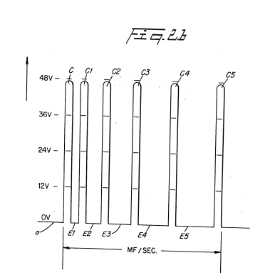
[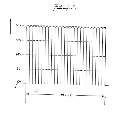](https://stanslegacy.com/uploads/images/gallery/2024-10/JAIBeamTRw65eAIy-image-1730144453044.png)With reference to the graph of Figure 2, the direct current input voltage is a pulsed at a repetition rate, as shown by waveform b, (per second) equal to the frequency of the resonant cavity. To enhance the forceful action of the applied pulsed direct current voltage/potential on the water molecule and the sub-atomic action for the release of gasses, the pulsing of the direct current is periodically interrupted as shown in the graph of Figure 2A.That is, the pulse frequency and pulsed direct current c1, c2, is interrupted in uniform intervals d1, d2 and d3.
Again, the pulsed direct current may be aperiodically interrupted.
| [](https://stanslegacy.com/uploads/images/gallery/2024-10/JAIBeamTRw65eAIy-image-1730144453044.png) | [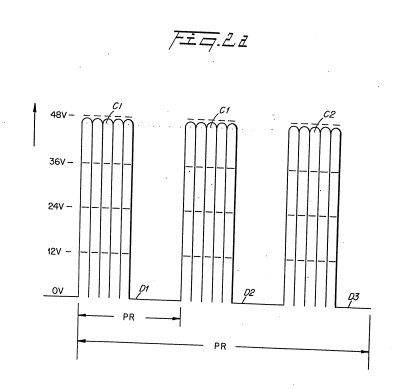](https://stanslegacy.com/uploads/images/gallery/2024-10/ugHsp2zoqRsJAv4J-image-1730144461245.png) |
That is, the interruption between pulses c,c1,c2,c, c\_1, c\_2, and c3c\_3 ... is for different time periods: e1,e2,e\_1, e\_2, and e3e\_3.
[](https://stanslegacy.com/uploads/images/gallery/2024-10/uJc1KoWTbR6GG7bM-image-1730143685782.png)Returning to Figure 1, an opening 8 is provided in the uppermost portion of the outer sphere 9 of the resonant cavity 3 structure. The travel of the gas atoms 7 bombarding back and forth in the resonant cavity 3 will eventually pass through the opening 8. However, the movement of the gas atoms 7 has been enhanced as aforesaid and when they pass through the opening 8 they are at an extremely high velocity. That is, the motion of the gas atoms 7 will pass out of opening 8 as though they are jet propelled. The structure of Figure 1 is that of a sphere 9 with another sphere 15 positioned therein. The spacing between the outer surface of the inner sphere 15 to the inner wall 9a of sphere 9 provides a resonant cavity to a given frequency of the physical force of the direct current voltage. Other resonant cavities may be utilized in other arrangements.| [](https://stanslegacy.com/uploads/images/gallery/2024-10/uJc1KoWTbR6GG7bM-image-1730143685782.png) | [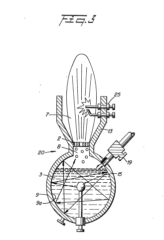](https://stanslegacy.com/uploads/images/gallery/2024-10/CW20dCOCr5LkpspF-image-1730144481452.png) |
The resonant cavities will enhance the release of the gasses in the sub-atomic action, irrespective of its configuration.
However, which structure is most productive may be related to its utilization in an operable embodiment.
| [](https://stanslegacy.com/uploads/images/gallery/2024-10/uJc1KoWTbR6GG7bM-image-1730143685782.png) | [](https://stanslegacy.com/uploads/images/gallery/2024-10/CW20dCOCr5LkpspF-image-1730144481452.png) | [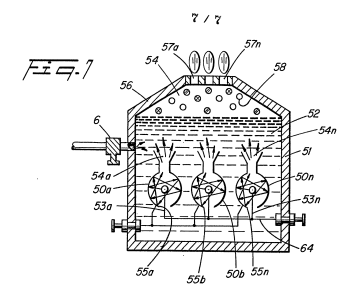](https://stanslegacy.com/uploads/images/gallery/2024-10/BjfRB5qJf89e0XOz-image-1730144512717.png) |
| [](https://stanslegacy.com/uploads/images/gallery/2024-10/BjfRB5qJf89e0XOz-image-1730144512717.png) | [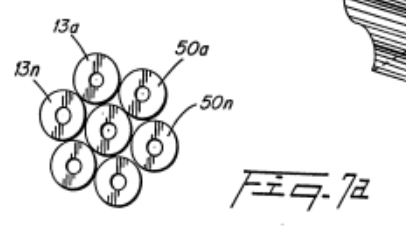](https://stanslegacy.com/uploads/images/gallery/2024-10/yCrIAFdqDmKHRgIl-image-1730146039399.png) |
| [](https://stanslegacy.com/uploads/images/gallery/2024-10/BjfRB5qJf89e0XOz-image-1730144512717.png) | [](https://stanslegacy.com/uploads/images/gallery/2024-10/CW20dCOCr5LkpspF-image-1730144481452.png) |
| [](https://stanslegacy.com/uploads/images/gallery/2024-10/uJc1KoWTbR6GG7bM-image-1730143685782.png) | [](https://stanslegacy.com/uploads/images/gallery/2024-10/JAIBeamTRw65eAIy-image-1730144453044.png) | [](https://stanslegacy.com/uploads/images/gallery/2024-10/ugHsp2zoqRsJAv4J-image-1730144461245.png) |
| [](https://stanslegacy.com/uploads/images/gallery/2024-10/KUZT2JE78Yk6AUb8-image-1730144469732.png) | [](https://stanslegacy.com/uploads/images/gallery/2024-10/CW20dCOCr5LkpspF-image-1730144481452.png) | [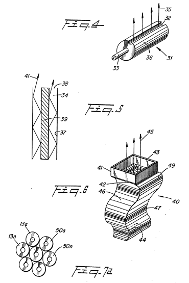](https://stanslegacy.com/uploads/images/gallery/2024-10/6KWnpmLtlr5wdXeZ-image-1730144498308.png) |
| [](https://stanslegacy.com/uploads/images/gallery/2024-10/BjfRB5qJf89e0XOz-image-1730144512717.png) | [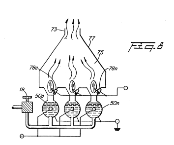](https://stanslegacy.com/uploads/images/gallery/2024-10/tm8jApcWN9yHDZPm-image-1730144520715.png) |
Source: [SMeyer-EP0103656A3-Resonant\_Cavity\_for\_a\_Hydrogen\_Generator.pdf](https://stanslegacy.com/attachments/276)
> **EUROPEAN PATENT APPLICATION** > > 21. **Application number:** 82111598.7 > 22. **Date of filing:** 14.12.82 > > --- > > 30. **Priority:** 24.09.82 US 422594 > 31. **Date of publication of application:** 28.03.84 Bulletin 84/13 > 32. **Date of deferred publication of search report:** 22.08.84 > 33. **Designated Contracting States:** AT BE CH DE FR GB IT LU NL SE > > --- > > 71. **Applicant:** Meyer, Stanley A. > 3792 Broadway > Grove City Ohio 43123 (US) > 72. **Inventor:** Meyer, Stanley A. > 3792 Broadway > Grove City Ohio 43123 (US) > 73. **Representative:** Wassmeier, Alfons, Dipl.-Ing. et al > Postfach 382 Gräfingerstrasse 7 > D-8400 Regensburg (DE) --- #### Resonant cavity for a hydrogen generator. [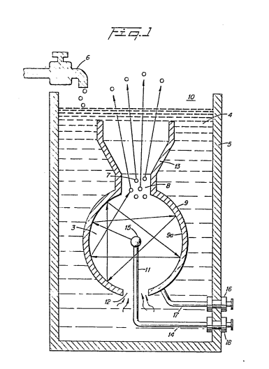](https://stanslegacy.com/uploads/images/gallery/2024-10/xPnMrn0q0w9hUN2A-image-1730146214748.png)A direct current voltage exciter for utilization in a non-electrolysis process and apparatus for separating hydrogen-oxygen gas from water. The non-oxidizing exciters comprise a plate structure with negative potential applied to one such **exciter plate** (9) and a positive potential applied to the **other** (15). The spacing between plates comprises a **resonant cavity** (3) to a particular frequency. The direct current voltage is pulsed at a repetition rate that matches the frequency of the **resonant cavity** (3). The sub-atomic action of the direct current voltage on the plates is enhanced considerably by the bombardment of the atoms within the resonant structure. A spherical plate construction is described with alternative structures of a resonant unit. # EP0106917A1 Gas Electrical Hydrogen Generator #### **Gas electrical hydrogen generator.** [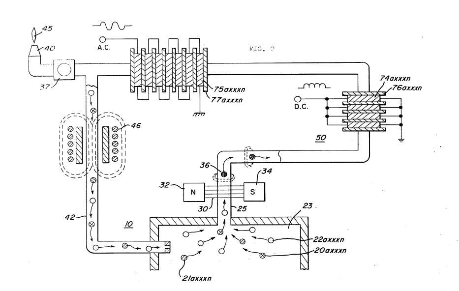](https://stanslegacy.com/uploads/images/gallery/2024-10/VevvKG25pXlQttOe-image-1730147139832.png)A hydrogen gas generator system for converting water into hydrogen and oxygen gasses, in combination with a magnetic particle accelerator for voltage/current amplification. The hydrogen gas generator encompasses an array of plates immersed in water in a pressure-tight enclosure. Direct current voltage applied to the plates causes the hydrogen/oxygen gasses to disassociate from the water molecule. The upper portion of the container is a hydrogen/oxygen collection chamber for maintaining a predetermined gas pressure. A hydrogen/oxygen gas mixture outlet means connected to the collection chamber of the generator includes a magnetic particle accelerator in magnetic relationship with the primary winding for imparting a magnetic potential to the hydrogen gas and the oxygen gas atoms as they are being pressure released from the collection chamber. Attached to the gas outlet means is a non-magnetic conductive loop or tubing. A coil wound around the tubing will have a voltage induced therein as the pressure velocity polarized magnetized gas particles pass therethrough. The induced voltage is used as an electrical power source. The hydrogen and oxygen gas may be utilized such as a burner system or alternatively returned to the gas storage area of the hydrogen generator in a closed-loop arrangement for recycling. ##### **CROSS REFERENCE AND BACKGROUND:** > There is disclosed in my co-pending patent application, filed, September 16, 1981, Serial Number, 302,807, for, Hydrogen Generator, a hydrogen gas generating system. The apparatus comprises a pressure-tight enclosure for a water bath having immersed therein an array of plates. The hydrogen and oxygen atoms are disassociated from the water molecule by the application of a non-regulated, non-filtered, low-power, direct current voltage potential to the plates having water passing therebetween. The plates are non-oxidizing and of similar metal to comprise a sub-atomic action non-electrolysis system. The upper portion of the container is a hydrogen/oxygen storage chamber for maintaining a predetermined level. > In my co-pending patent application, Serial Number: 411,977, for, Controlled Hydrogen Gas Flame, filed, August 25, 1982, there is disclosed a hydrogen gas burner. The nozzle in that burner is connected to the storage area or gas collection chamber via an appropriate line. The port in the nozzle has an opening of a controlled size and configuration, related to the size of the flame and the temperature and velocity of the burning gas mixture. > Also, in my co-pending patent application, Serial Number 367,051, for Electrical Particle Generator, filed April 4, 1982, there is disclosed an electrical generating system. The non-magnetic pipe is filled with the discrete gas particles having a magnetic polarized field placed thereon. The magnetic charged gas particles proceed through the pipe at a high velocity dependent on the pressure in the gas generator storage chamber. As the magnetic particles pass through the core of the winding there is induced a voltage/current therein, that may be utilized in the same manner as any other electrical source. > The hydrogen/oxygen gas mixture emitted from the opposite end of the pipe is connected to a gas burner where the hydrogen/oxygen gas mixture may be utilized such as for a flame as shown in my co-pending application, Serial number, 411,977. When the flame is not in use the gas is directed back by alternate means to the storage chamber in the hydrogen generator in a closed loop arrangement. ##### **SUMMARY OF INVENTION:** The present invention utilizes the basic principle of a particle accelerator and the principle of inducing a voltage current in a secondary winding by passing a magnetic element therethrough in combination with a hydrogen gas generator. The particle accelerator utilizes the principles of my co-pending application, Serial Number, 367,051, and the hydrogen generator is particularly that of my co-pending patent application, 302,807. The structure comprises an electrical inductive winding, having a large number of turns and an output for utilizing the voltage current induced therein. The inductive winding is positioned around an endless - closed loop, non-magnetic pipe or tubing. The hydrogen gas generator encompasses an array of plates immersed in a pressure-tight enclosure. Direct current voltage applied to the plates causes the hydrogen/oxygen gasses to disassociate from the water molecule. The upper portion of the container is a hydrogen/oxygen storage chamber for maintaining a predetermined gas pressure. A hydrogen/oxygen gas mixture outlet means connects the non-magnetic tubing to the storage chamber of the generator. Adjacent the outlet a magnetic polarizer establishes a magnetic field and imparts a magnetic potential to the hydrogen and the oxygen gas being pressure released from the outlet. The apparatus comprises a non-magnetic pipe in a closed loop having a substantial amount of magnetized particles encapsulated therein. A magnetic accelerator assembly is positioned on the pipe and includes an inductive primary winding with a low voltage input. A secondary winding is positioned on the pipe opposite to the primary winding. Upon voltage being applied to the primary winding, the magnetized particles accelerate through the magnetic accelerator assembly with increased velocity. The velocity-accelerated particles induce an electrical voltage/current potential as they pass through the secondary winding. In a closed-loop system, the process is continuous. The increased secondary voltage current is utilized in a direct current or alternate current amplifier arrangement. ##### **OBJECTS:** It is a principal object of the present invention to provide a hydrogen gas electrical generator capable of producing a voltage/current much greater in magnitude heretofore possible. Another object of the present invention is to provide such a hydrogen gas electrical generator utilizing magnetized elements and wherein the magnetized elements are charged gas particles from a hydrogen generator. Another object of the present invention is to provide such a hydrogen gas electrical generator in combination with a controlled output hydrogen generator. Another object of the present invention is to provide such an electrical generator that may be utilized with a hydrogen generator having another utility output for alternative generation. A further object of the present invention is to provide such an electrical generator that utilizes components readily available and adaptable to the simplified embodiment. Other objects and features of the present invention will become apparent from the following detailed description when taken in conjunction with the drawings in which: **BRIEF DESCRIPTION OF DRAWINGS** Figure 1 is a simplified illustration of the principles of the invention, in cross-section showing the particles voltage/current amplifier together with the hydrogen generator in a preferred embodiment. Figure 2 is a magnetic particle tubing, in an electrical schematic circuit arrangement, illustrating the induced direct and alternating current voltage.| [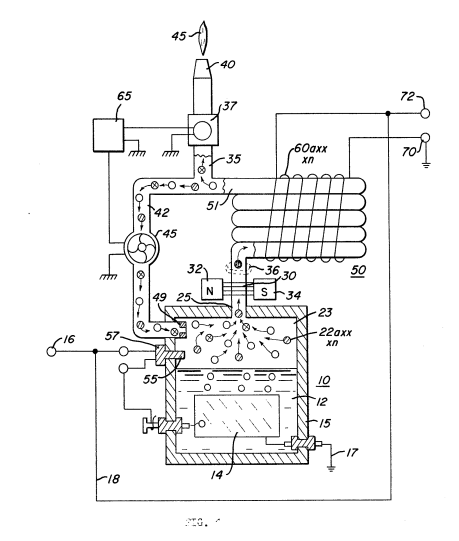](https://stanslegacy.com/uploads/images/gallery/2024-10/c49c0ZLFfMbYD3yD-image-1730147161861.png) | [](https://stanslegacy.com/uploads/images/gallery/2024-10/VevvKG25pXlQttOe-image-1730147139832.png) |
Although certain and specific embodiments are shown and described, alternatives and modifications may be had without departing from the spirit and scope of the invention.
##### CLAIMS: 1. **In combination, a hydrogen/oxygen electrical generator comprising:** - a housing having a water reservoir for retaining natural water therein and a gas collection chamber maintaining a preset volume of gas under pressure, - a pair of similar non-oxidizing plates positioned in said water reservoir, - a direct current voltage source connected to said plates to cause a sub-atomic force-type action on said water, said action disassociating the hydrogen atoms and oxygen atoms from said water molecules; and - a non-magnetic tubing for passing magnetic lines of force, connected at one end to said collection chamber via said outlet, - a magnetic polarizer positioned adjacent to said one end of said tubing for magnetically charging said hydrogen and oxygen gas atoms pressure expelled from said outlet, - an inductive winding positioned over said tubing; and wherein the flux lines of said magnetized gas passing through said tubing and traversing said inductive winding induce a current/voltage in said inductive winding, and, said winding having means for utilization of said induced voltage/current. 2. **The combination of Claim 1 further comprising:** gas utilization means connected to the other end of said tubing for utilizing said generated hydrogen/oxygen gas mixture. 3. **The combination of Claim 1 further comprising:** a nozzle connected to the other end of said tubing, of a predetermined size and configuration, having a port for expelling said mixed gasses, and means for igniting said gasses. 4. **The combination of Claim 1 further comprising:** control means for maintaining a predetermined gas pressure in said collection chamber. 5. **The combination of Claim 1 further comprising:** a pressure gauge for determining the pressure in said collection chamber, and switch means connected to said direct current voltage source to terminate the generation of hydrogen/oxygen gasses upon said collection chamber attaining a predetermined pressure. 6. **The combination of Claim 1 further comprising:** a gas line tubing connected to the other end of said non-magnetic tubing and to said collection chamber in a closed loop arrangement. 7. **The combination of Claim 1 further comprising:** a gas line tubing connecting the other end of said non-magnetic tubing to said collection chamber in a closed loop arrangement, and means in said gas line tubing for maintaining said polarized hydrogen and oxygen atoms circulating through said non-magnetic tubing. 8. **The combination of Claim 1 further comprising:** a gas line tubing connected to the other end of said non-magnetic tubing to said collection chamber in a closed loop arrangement, and a unidirectional valve connected to the end of said gas line tubing connected to said collection chamber. 9. **The combination of Claim 1 further comprising**: a gas line tubing and gas utilization means, a Y-type connector for alternately connecting said gas line tubing to said gas utilization means and said collection chamber in a closed loop arrangement. 10. **The combination of Claim 1 further comprising:** a gas line tubing and gas utilization means, a Y-type connector for alternately connecting said gas line tubing to said gas utilization means said collection chamber in a closed loop arrangement, two directional valve means, and a demand circuit connected to said valve means for selectively connecting said gas line tubing to said gas utilization means or said collection chamber in response to pre-determined conditions. 11. **In combination, a gas electrical generator comprising:** a gas generator housing having a gas collection chamber for maintaining a preset volume of gas therein under pressure, an outlet attached to said gas collection chamber, a non-magnetic tubing connected to the opposite end of said outlet, a magnetic polarizer positioned adjacent to said outlet between said chamber and said tubing for magnetically charging said gas pressure expelled from said outlet, an inductive coil positioned over said non-magnetic tubing and wherein the flux lines of said magnetized gas passing through said tubing and traversing said inductive coil, induce a current/voltage therein, means connected to said coil for utilization of said induced voltage/current. 12. **The gas electrical generator of Claim 11 wherein:** said gas is a combustible gas, and utilization means connected to the opposite end of said non-magnetic tubing for utilizing said gasses. 13. **The combination of a gas electrical generator as set forth in claim 11 wherein:** said coil comprises a plurality of windings wound in parallel, and wherein said induced voltage/current therein is of a single polarity. 14. **The combination of a gas electrical generator as set forth in Claim 11 wherein:** said coil comprises a plurality of windings wound in series, and wherein said induced voltage/current therein is of alternate polarities. 15. **The combination of a gas electrical generator as set forth in Claim 11 wherein:** said coil comprises a plurality of windings and wherein the number of said plurality of windings is determinative of the frequency of the said induced voltage/current therein. 16. **The combination of a gas electrical generator as set forth in Claim 11 further comprising:** means for varying the pressure of said gas in said collection chamber to vary the output frequency of said induced voltage in said coils. 17. **The combination of a gas electrical generator as set forth in Claim 11 further comprising:** means for varying the generation of said gas to vary the pressure of said gas in said collection chamber to vary the output frequency of said induced voltage in said coils. 18. **The combination of a gas electrical generator as set forth in Claim 11 further comprising:** means for adding non-combustible gases to said collection chamber to vary the pressure of said gas in said collection chamber to vary the output frequency of said induced voltage in said coils. 19. **The gas electrical generator of Claim 11 wherein:** said non-magnetic tubing further comprises means connected thereto for returning said magnetized gas to said collection chamber, and means for recirculating said gas through said chamber, said non-magnetic tubing and said last named means. 20. **The gas electrical generator of Claim 11 wherein:** said non-magnetic tubing further comprises means connected thereto for returning said magnetized gas to said collection chamber, a particle accelerator for recirculating said gas through said chamber, said tubing, and said last named means.| [](https://stanslegacy.com/uploads/images/gallery/2024-10/c49c0ZLFfMbYD3yD-image-1730147161861.png) | [](https://stanslegacy.com/uploads/images/gallery/2024-10/VevvKG25pXlQttOe-image-1730147139832.png) |