Experiments
- Capacitor Bank for Magnetizer Machine
- Leedskalnin PMH And Potential Application to EPG Magnetization
Capacitor Bank for Magnetizer Machine
As mentioned in the 2019 conference talk, it was stated that modern permanent magnets are made via capacitor bank discharge into a large inductance. A YouTube video seeing how this is done can be found here: Magnetizer Machine
In this machines, a capacitor bank is charged up to a high voltage. This charge is then dumped, usually by an large SCR. In electrical engineering, a capacitor's current is based upon the rate of change in voltage with respect to a change in time, or I = dV/dT. Therefore, a fast closure of a switch (SCR) causes this energy to be dumped into an inductance. We know from photos of the EPG, that all coils were wired in parallel. When coils are wired in parallel, their overall inductance is reduced to less than one of the inductances (same principle applies to resistors). This reduction in inductance presents a lower inductive reactance to the impulse current, which allows an intense Electromagnetic field to be produced, aligning the dipoles of whatever is placed within the center.
It should be understood that magnetism is an attribute of an object, not a principle. We can heat up NdFeB magnets, or C8 ferrite magnets and remove the magnetism. NdFeB/C8 magnets are magnetized in the same process as shown in the video. When these are pressed together to form neutral chunks of material, they're not magnets until after the process. Additionally, most magnets have ceramic or non-magnetic (but dielectric) materials within. This creates a lattice (like Argon and Iron) where ferromagnetic materials are separated via a insulative material.
Leedskalnin PMH And Potential Application to EPG Magnetization
In 2019 Ethan Crowder spoke at Stan Meyer Conference in Bremen Ohio. This link (Ethan's EPG Speculation) is to a shortened YouTube excerpt that covers his speculation of how Stan Meyer may have magnetized the medium inside the EPG via capacitor bank discharging. This method is how modern permanent magnets are produced.
After 2019, additional information surfaced that reinforced what Ethan Crowder was talking about: "Once said tubular pathway (1) as to (8) is completely filled with said permanently magnetized material (3), said pickup coil-array (2a xxx 2n) is electrically energized to produce an electromagnetic field that completely surrounds said tubular pathway (8). Exposing said magnetic material (3) to said electromagnetic field...causing said material (3) to become permanently magnetized...forming a longitudinal field (4), emitting from said tubular pathway (1). Said longitudinal field (4) remains after said coil-array (2a xxx 2n) is de-energized. No other energy is needed to maintain said magnetic field (4)."
"Fill said closed loop tubular pathway (1) as to (8) with a permanently magnetized material (3), as illustrated in Figure 27. Said permanently magnetized material (3) can either be in a liquid slurry and/or gas form. Said liquid slurry is composed of micro size permanently magnetized particles suspended in a fluid-medium such as liquid Teflon or light-oil, forming a homogenous liquid-mass. Said permanently magnetized gas is composed of atom-size permanently magnetic particles suspended onto an inert carrier gas such as nitrogen or argon, forming a homogenous gas-mass. Both homogenous masses can be doped with different permanently magnetized atoms to encourage electromagnetic field enhancement."
Edward Leedskalnin wrote a book titled Magnetic Currents. He details two "magnetic currents" rotating in opposing directions,
intersecting with one another. His "Perpetual Motion Holder" is a device that maintains a permanent magnetic state due to setting these two opposing directional vortices in motion via a short current impulse from a battery or capacitor. Additionally, Albert Roy Davis and Walter C Rawls detailed the same observances in their books "Magnetism and Its Effects On Living Systems".
It should be notated that a patent by Stan titled "Rotary Pulse Generator" patent # details effects that are claimed to have no opposing magnetic field effect. Particularly, with a single coil being rotated within bipolar (N/S) fields. This bipolar magnetic field would be exhibited by the medium contained within the EPG. Whether this is a gaseous matrix or semi-solid slurry. One may be able to view the rotary patent as an inside-out EPG.
PARALLEL COIL ARRANGEMENT:
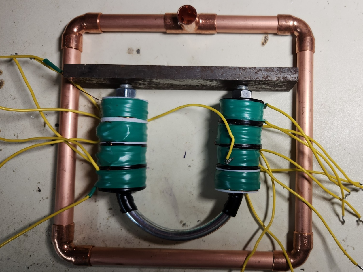
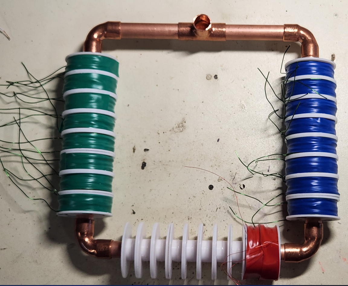
EPG models had all their pickup coils wired in a parallel arrangement, connected to brass bus bars. A PMH was wrapped with banks of coils to provide an analogy for EPG coils.
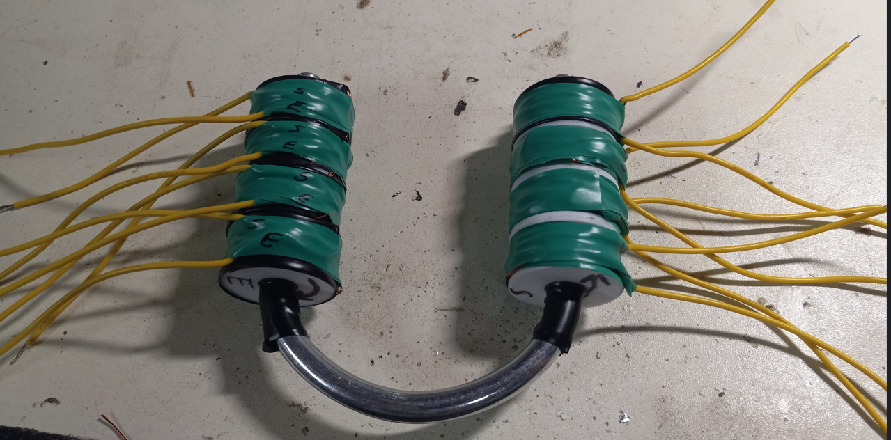
Photos below are lab note book screenshots of the results.
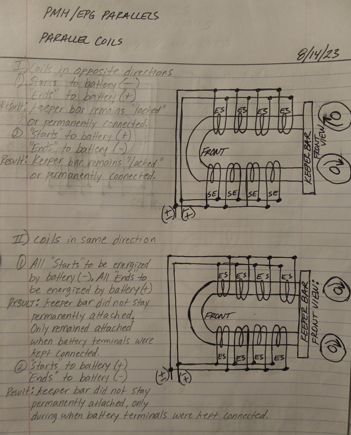
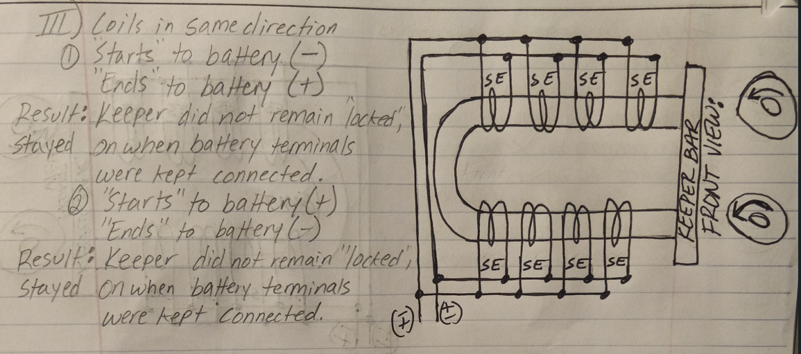
Keeper bar only remained locked in a "permanent" state when the coils were arranged to have winding directions in opposing directions. Two single coils can produce the same effect, only if their winding directions are opposing.
EPG TEST SETUP:
The above experimentations demonstrated counter directional electromagnets can be advantageous in producing a permanent magnetic state within a core material. Below shows an experimental setup for attempting making a permanently magnetized slurry with Leedskalnin PMH methodology. This setup will also serve for capacitor bank discharge magnetization attempts. Ferrofluid was purchased (matching Stan's estate photo). Additionally, 325 mesh size Nickel/Iron powder with a carrier fluid will be investigated.