International Patents
1989 Through 1992
- WO9207861A1 - International Patent
- WO8912704A1 - Process And Apparatus For The Production Of Fuel Gas And The Enhanced Release Of Thermal Energy From Such Gas
- WO9222679A1 - Water Fuel Injection System
- WO8901464A3 - Controlled Process for the Production of Thermal Energy from Gases and Apparatus Useful Therefor
- WO9208046A1 - Hydrogen Gas Fuel & Management System For An Internal Combustion Engine
WO9207861A1 - International Patent
PDF Download: SMeyer-WO9207861A1-International_Patent.pdf
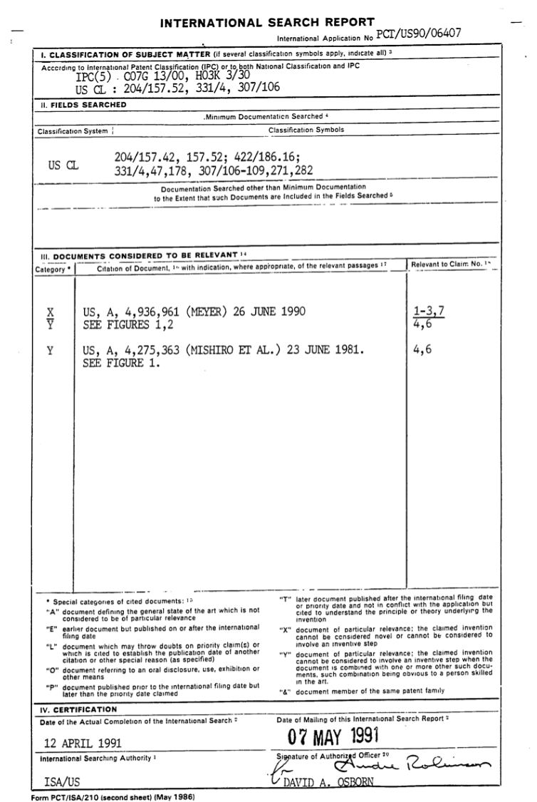
This invention relates to electrical circuit systems useful in the operation of a water fuel cell including a water capacitor/resonant cavity for the production of a hydrogen containing fuel gas, such as that described in my United States Letter Patent No. 4,936,961, "Method for the Production of a Fuel Gas", issued on June 26, 1990.
REFERENCE: Patent No. 4,936,961, "Method for the Production of a Fuel Gas", issued on June 26, 1990.
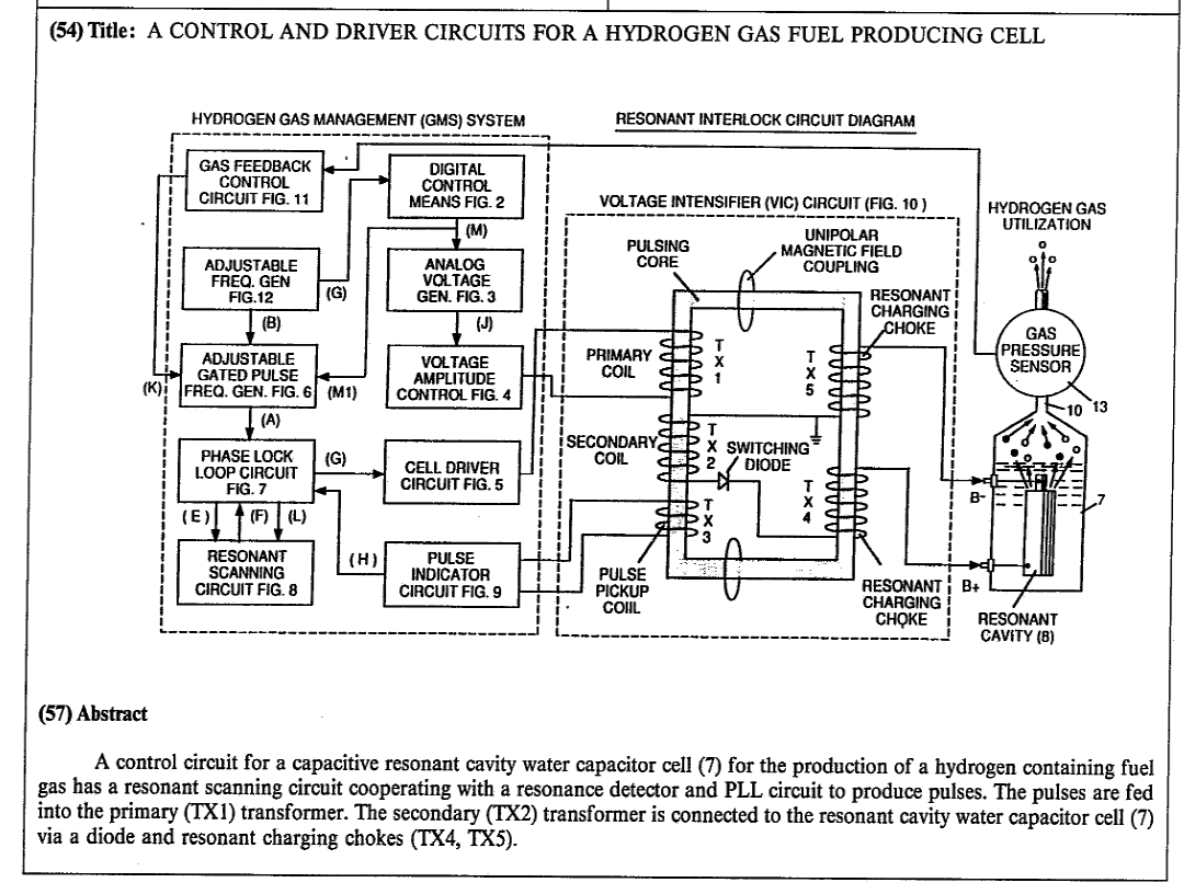
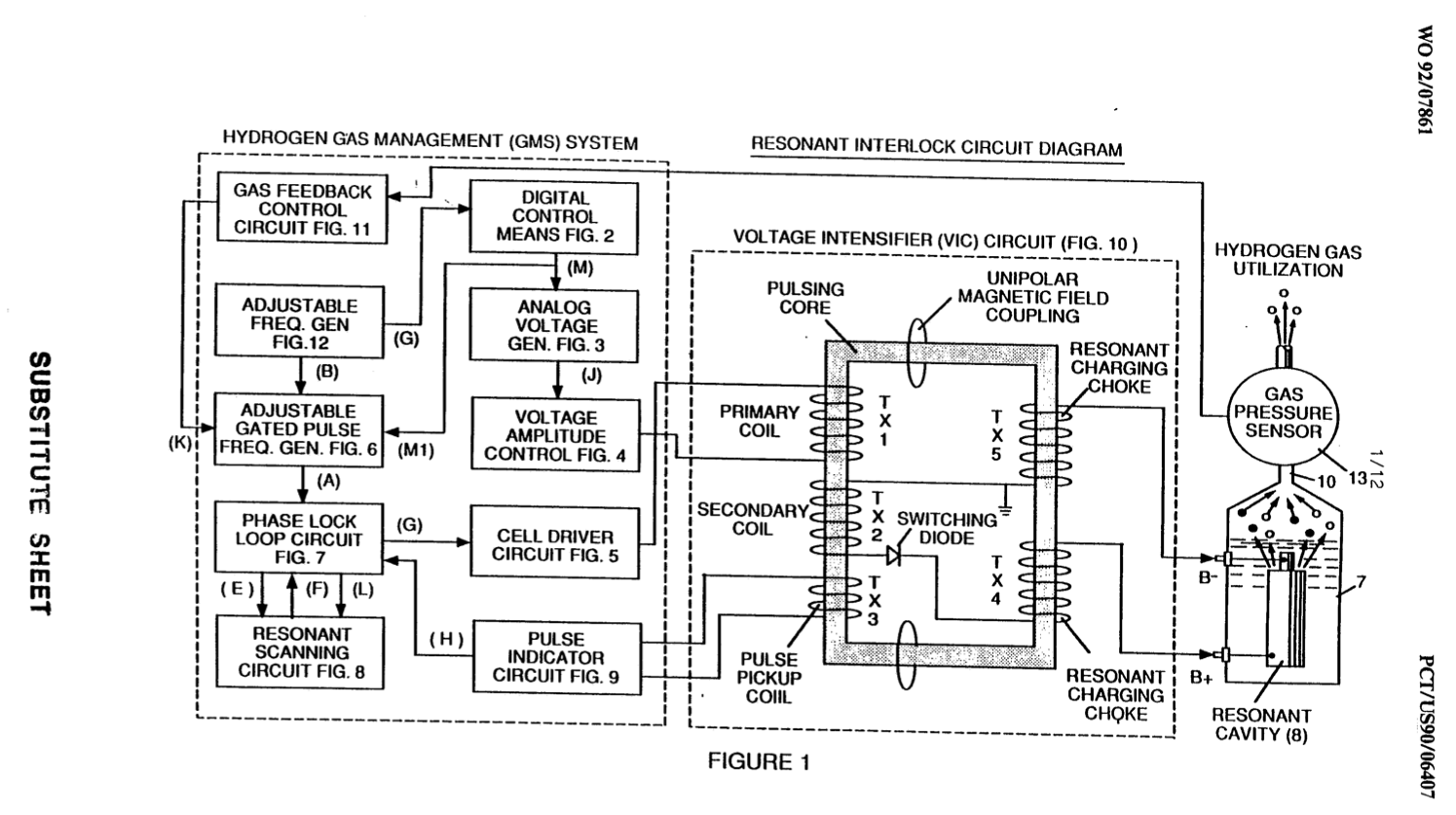
Image Text: A control circuit for a capacitive resonant cavity water capacitor cell (7) for the production of a hydrogen containing fuel gas has a resonant scanning circuit cooperating with a resonance detector and PLL circuit to produce pulses. The pulses are fed into the primary (TX1) transformer. The secondary (TX2) transformer is connected to the resonant cavity water capacitor cell (7) via a diode and resonant charging chokes (TX4, TX5).
In my aforesaid Letters Patent for a method for the production of a fuel gas, voltage pulses applied to plates of a water capacitor tune into the dielectric properties of the water and attenuate the electrical forces between the hydrogen and oxygen atoms of the molecule. The attenuation of the electrical forces results in a change in the molecular electrical field and the covalent atomic bonding forces of the hydrogen and oxygen atoms. When resonance is achieved, the atomic bond of the molecule is broken, and the atoms of the molecule disassociate. At resonance, the current (amp) draw from a power source to the water capacitor is minimized and voltage across the water capacitor increases. Electron flow is not permitted (except at the minimum, corresponding to leakage resulting from the residual conductive properties of water).
For the process to continue, however, a resonant condition must be maintained.
Because of the electrical polarity of the water molecule, the fields produced in the water capacitor respectively attract and repel the opposite and like charges in the molecule, and the forces eventually achieved at resonance are such that the strength of the covalent bonding force in the water molecule is exceeded, and the atoms of the water molecule (which are normally in an electron sharing mode) disassociate. Upon disassociation, the formerly shared bonding electrons migrate to the hydrogen nuclei, and both the hydrogen and oxygen revert to net zero electrical charge. The atoms are released from the water as a gas mixture.
In the invention herein, a control circuit for a resonant cavity water capacitor cell utilized for the production of a hydrogen containing fuel gas is provided.
The circuit includes an isolation means such as a transformer having a ferromagnetic, ceramic or other electromagnetic material core and having one side of a secondary coil connected in series with a high speed Switching diode to one plate of the water capacitor of the resonant cavity and the other side of the secondary coil connected to the other plate of the water capacitor to form a closed loop electronic circuit utilizing the dielectric properties of water as part of the electronic resonant circuit. The primary coil of the isolation transformer is connected to a pulse generation means. The secondary coil of the transformer may include segments that form resonant charging choke circuits in series with the water capacitor plates.
In the pulse generation means, an adjustable first, resonant frequency generator and a second gated pulse frequency generator are provided. A gate pulse controls the number of the pulses produced by the resonant frequency generator sent to the primary coil during a period determined by the gate frequency of the second pulse generator.
The invention also includes a means for sensing the occurrence of a resonant condition in the water capacitor/resonant cavity, which when a ferromagnetic or electromagnetic core is used, may be a pickup coil on the transformer core. The sensing means is interconnected to a scanning circuit and a phase lock loop circuit, whereby the pulsing frequency to the primary coil of the transformer is maintained at a sensed frequency corresponding to a resonant condition in the water capacitor.
Control means are provided in the circuit for adjusting the amplitude of a pulsing cycle sent to the primary coil and for maintaining the frequency of the pulsing cycle at a constant frequency regardless of pulse amplitude. In addition, the gated pulse frequency generator may be operatively interconnected with a sensor that monitors the rate of gas production from the cell and controls the number of pulses from the resonant frequency generator sent to the cell in a gated frequency in a correspondence with the rate of gas production. The sensor may be a gas pressure sensor in an enclosed water capacitor resonant cavity which also includes a gas outlet. The gas pressure sensor is operatively connected to the circuit to determine the rate of gas production with respect to ambient gas pressure in the water capacitor enclosure.
Thus, an omnibus control circuit and its discrete elements for maintaining and controlling the resonance and other aspects of the release of gas from a resonant cavity water cell is described herein and illustrated in the drawings which depict the following:
Figure 1 is a block diagram of an overall control circuit showing the interrelationship of sub-cireuits, the pulsing core/resonant circuit and the water capacitor resonant cavity.
Figure 1 - Overall Control Circuit Block Diagram
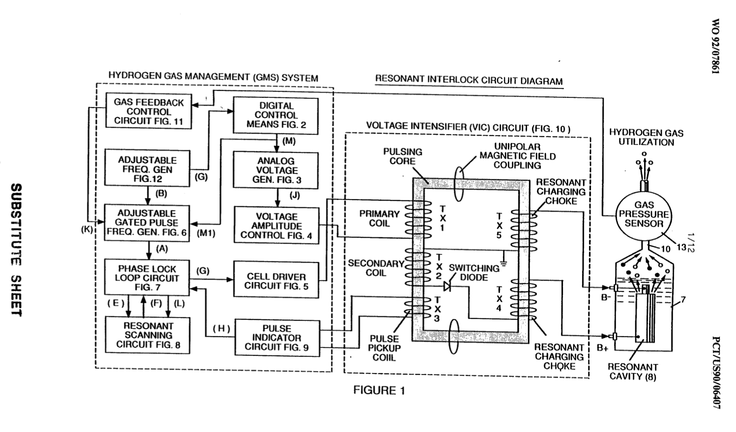
Figure 2 shows a type of digital control means for regulating the ultimate rate of gas production as determined by an external input. (Such a control means would correspond, for example, to the accelerator in an automobile or a building thermostat control.)
Figure 2 - Digital Control Means
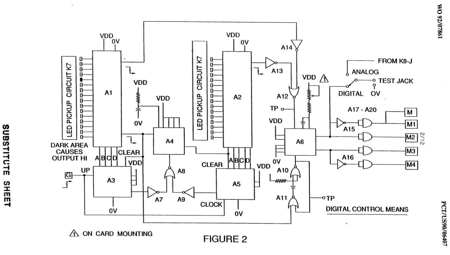
Figure 3 shows an analog voltage generator.
Figure 3 - Analog Voltage Generator
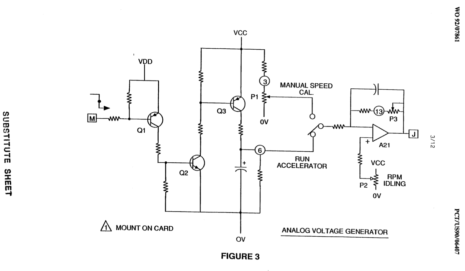
Figure 4 is a voltage amplitude control circuit interconnected with the voltage generator and one side of the primary coil of the pulsing core.
Figure 4 - Voltage Amplitude Control Circuit
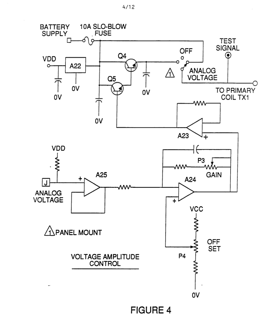
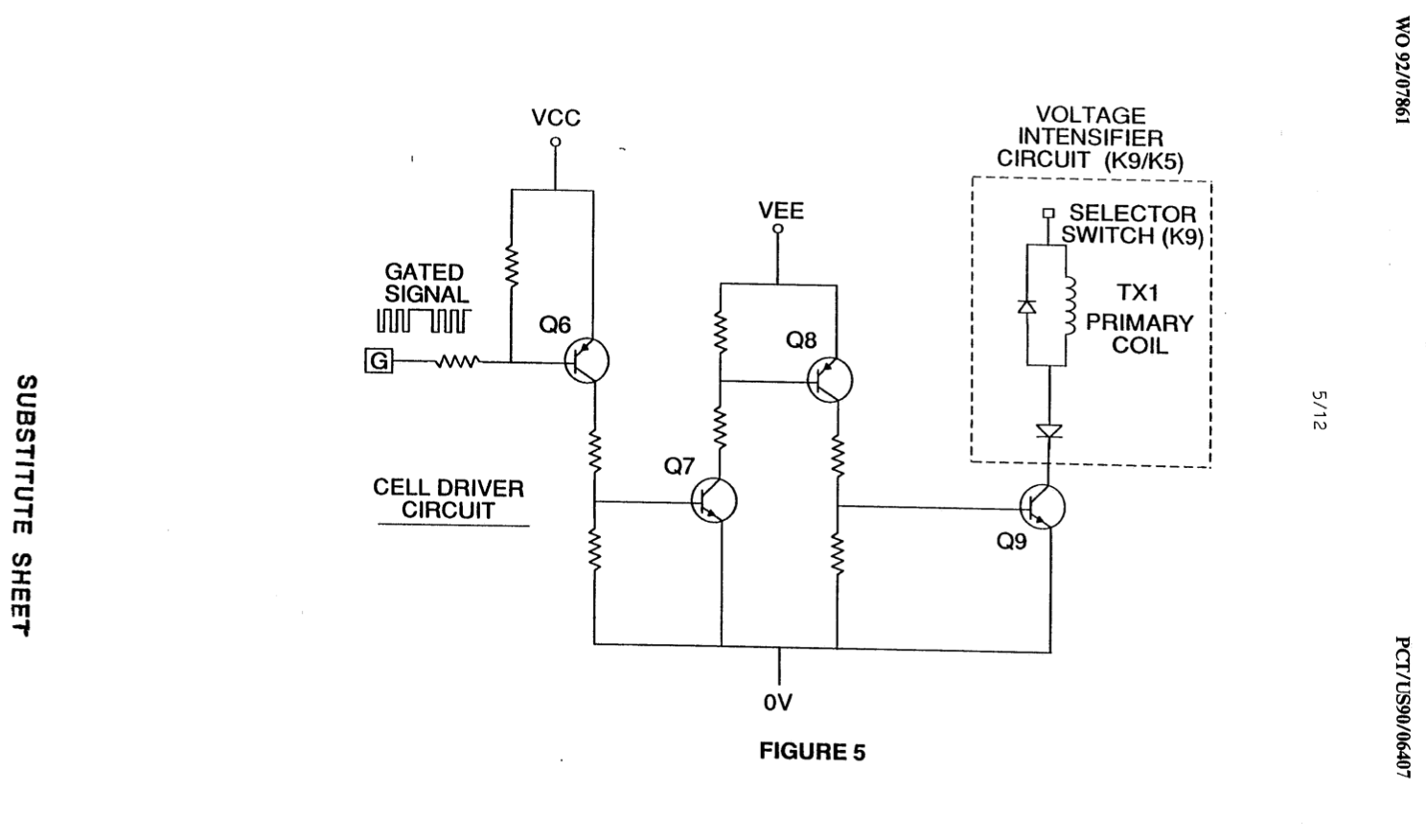
Figure 5 is the cell driver circuit that is connected with the opposite side of the primary coil of the pulsing core.
Figure 5 - Cell Driver Circuit
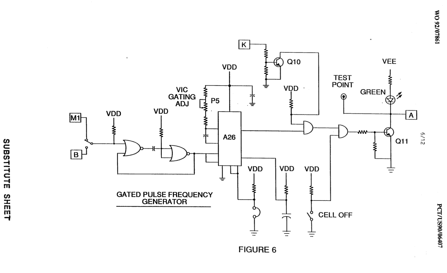
Figures 6, 7, 8 and 9 relate to pulsing control means including a gated pulse frequency generator (Figure 6): a phase lock circuit (Figure 7); a resonant scanning circuit (Figure 8); and the pulse indicator circuit (Figure 9) that control pulses transmitted to the resonant cavity/water fuel cell capacitor.
Figure 6: a phase lock circuit
Figure 6 - PLL Phase Lock Circuit
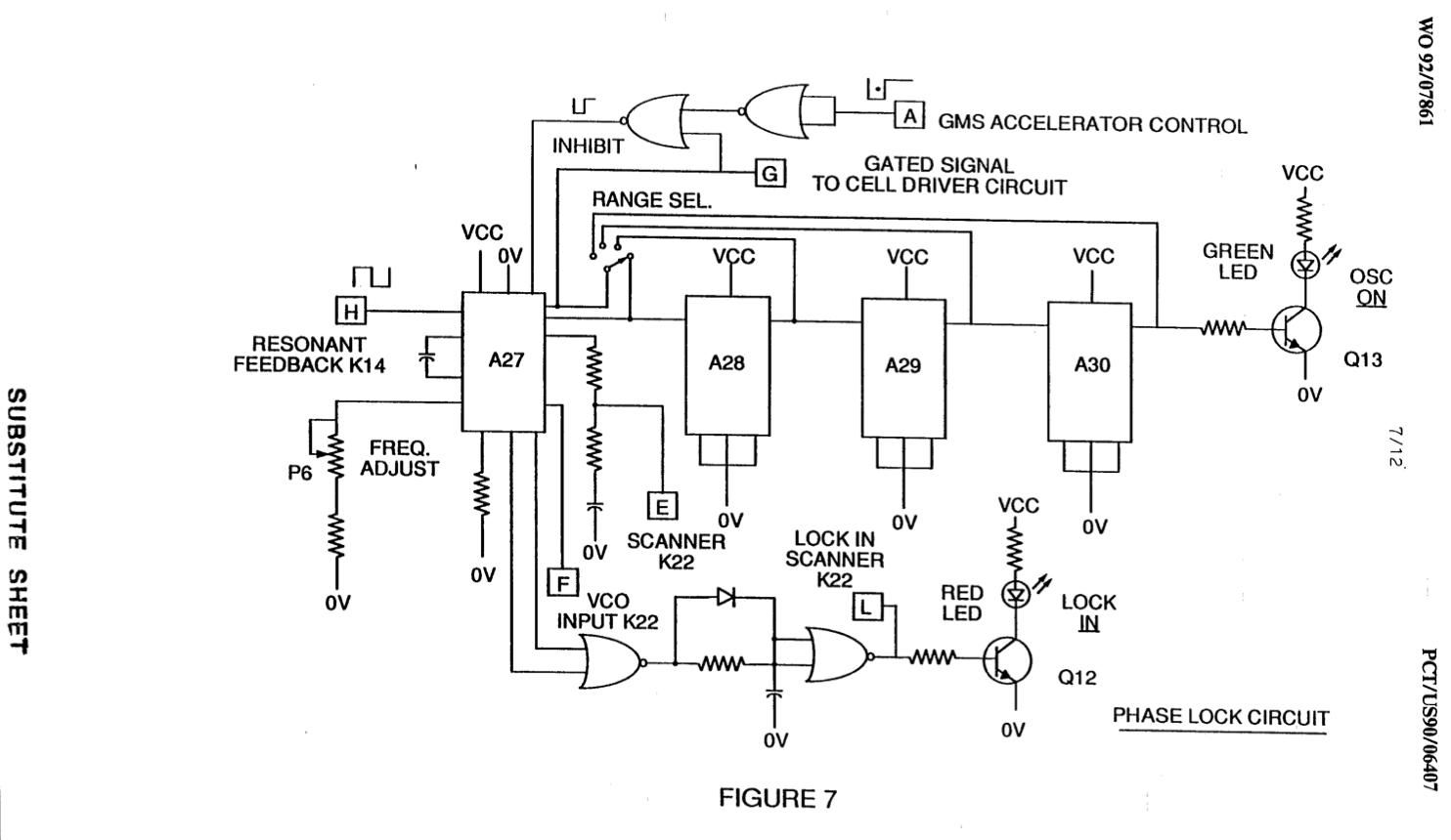
(Figure 7); a resonant scanning circuit
Figure 7 - Resonant Scanning Circuit
(Figure 8); and the pulse indicator circuit
Figure 8 - Pulse Indicator Circuit
(Figure 9): the pulse indicator circuit that control pulses transmitted to the resonant cavity/water fuel cell capacitor.
Figure 9 - PLL Feedback Circuit
Figure 10 shows the pulsing core and the voltage intensifier circuit that is the interface between the control circuit and the resonant cavity.
Figure 10 - VIC Interface
Figure 11 is a gas feedback control circuit.
Figure 11 - Gas Feedback Control Circuit
Figure 12 is an adjustable frequency generator circuit.
Figure 12 - Adjustable Frequency Generator Circuit
 The circuits are operatively interconnected as shown in Figure 1 and to the pulsing core voltage intensifier circuit of Figure 10, which, inter alia, electrically isolates the water capacitor so that it becomes an electrically isolated cavity for the processing of water in accordance with its dielectric resonance properties. By reason of the isolation, power consumption in the control and driving circuits is minimized when resonance occurs; and current demand is minimized as voltage is maximized in the gas production mode of the water capacitor/fuel cell.
inter alia: (adverb) - among other things.
 |
|
The reference letters appearing in the Figures, A, B, C, D, E, etc., to M and Ml show, with respect to each separate circuit depicted, the point at which a connection in that circuit is made to a companion or interrelated circuit.
In the invention, the water capacitor is subjected to a duty pulse which builds up in the resonant changing choke coil and then collapses. This occurrence permits a uni-polar pulse to be applied to the fuel cell capacitor. When a resonant condition of the circuit is locked-in by the circuit, amp leakage is held to a minimum as the voltage which creates the dielectric field tends to infinity. Thus, when high voltage is detected upon resonance, the phase lock loop circuit that controls the cell driver circuit maintains the resonance at the detected (or sensed) frequency.
The resonance of the water capacitor cell is affected by the volume of water in the cell. The resonance of any given volume of water maintained in the water capacitor cell is also affected by "contaminants" in the water which act as a damper. For example, at an applied potential difference of 2000 to 5000 volts to the cell, an amp spike or surge may be caused by inconsistencies in water characteristics that cause an out-of-resonance condition which is remedied instantaneously by the control circuits.
In the invention, the adjustable frequency generator (Figure 12) tunes into the resonant condition of the circuit including the water cell and the water therein. The generator has a frequency capability of 0 - 10 KHz and tunes into resonance typically at a frequency of 5 KHz in a typical 3.0 inch water capacitor formed of a 0.5 inch rod enclosed within a 0.75 inside diameter cylinder.
At start up, in this example, current draw through the water cell will measure about 25 milliamp; however, when the circuit finds a tuned resonant condition, current drops to a 1-2 milliamp minimum leakage condition.
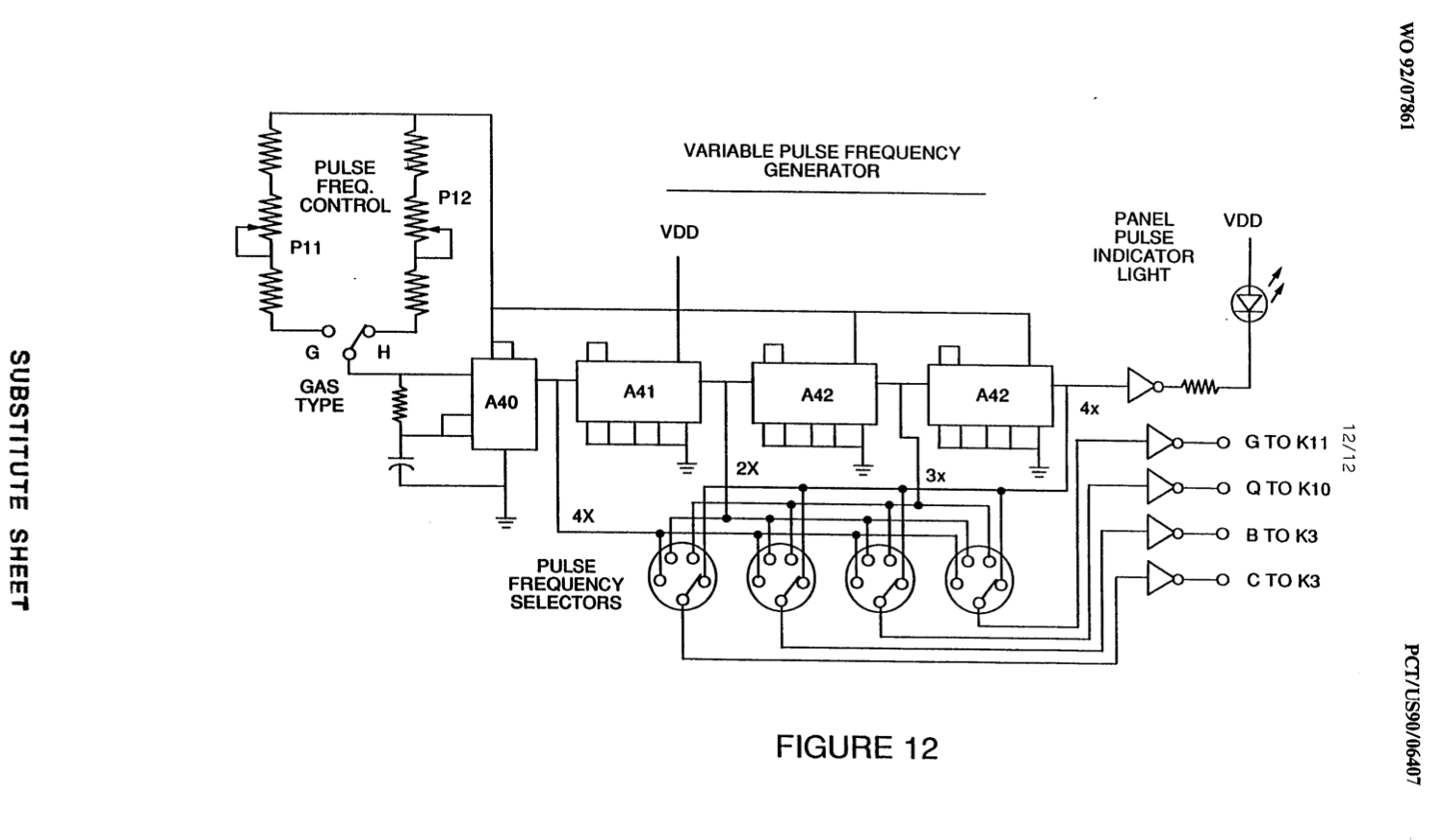
The voltage to the capacitor water cell increases according to the turns of the winding and size of the coils, as in a typical transformer circuit. For example, if 12 volts are sent to the primary coil of the pulsing core and the secondary coil resonant charging choke ratio is 30 to 1, then 360 volts are sent to the capacitor water cell. Turns are a design variable that control the voltage of the uni-polar pulses sent to the capacitor.
High Speed Switching Diode
The high speed switching diode shown in Figure 10 prevents charge leakage from the charged water in the water capacitor cavity, and the water capacitor as an overall capacitor circuit element, i.e., the pulse and charge status of the water/capacitor never pass through an arbitrary ground. The pulse to the water capacitor is always uni-polar, The water capacitor is electrically isolated from the control, input and driver circuits by the electromagnetic coupling through the core. The switching diode in the VIC circuit (Figure 10) performs several functions in the pulsing. The diode is an electronic switch that determines the generation and collapse of an electromagnetic field to permit the resonant charging choke(s) to double the applied frequency and also allows the pulse to be sent to the resonant cavity without discharging the "capacitor" therein. The diode, of course, is selected in accordance with the maximum voltage encountered in the pulsing circuit. A 600 PIV fast switching diode, such as an NVR 1550 high speed switching diode, has been found to be useful in the circuit herein,
The VIC circuit of Figure 10 also includes a ferromagnetic or ceramic ferromagnetic pulsing core capable of producing electromagnetic flux lines in response to an electrical pulse input. The flux lines equally affect the ‘secondary coil and the resonant charging choke windings. Preferably, the core is a closed loop construction. The effect of the core is to isolate the water capacitor and to prevent the pulsing signal from going below an arbitrary ground and to maintain the charge of the already charged water and water capacitor.
In the pulsing core, the coils are preferably wound in the same direction to maximize the additive effect of the electromagnetic field therein.
The magnetic field of the pulsing core is in synchronization with the pulse input to the primary coil. The potential from the secondary coil is introduced to the resonant charging choke({s) series circuit elements which are subjected to the same synchronous applied electromagnetic field, simultaneously with the primary pulse.
When resonance occurs, control of the gas output is achieved by varying voltage amplitude or varying the time of duty gate cycle. The transformer core is a pulse frequency doubler. In a figurative explanation of the workings of the fuel gas generator water capacitor cell, when a water molecule is “hit" by a pulse, electron time share is affected, and the molecule is charged. When the time of the duty cycle is changed, the number of pulses that “hit" the molecules in the fuel cell is correspondingly modified. More “hits" result in a greater rate of molecular disassociation.
With reference to the overall circuit of Figure 1, Figure 3 receives a digital input signal, and Figure 4 depicts the control means that directs 0-12 volts across the primary coil of the pulsing core. Depending upon design parameters of primary coil voltage and other Factors relevant to core design, the secondary coil of the pulsing core can be set up for a predetermined maximum, such as 2000 volts.
|
|
Figure 5, the cell driver circuit, allows a gated pulse to be varied in direct relation to voltage amplitude.
As noted above, the circuit of Figure 6 produces a gate pulse frequency. The gate pulse is superimposed over the resonant frequency pulse to create a duty cycle that determines the number of discrete pulses sent to the primary coil. For example, assuming a resonant pulse of 5 KHz, a 0.5 Hz gate pulse may be superimposed over the 5 KHz pulse to provide 2500 discrete pulses in a 50% duty cycle per Hz. The relationship of resonant pulse to the gate pulse is determined by conventional signal addition/subtraction techniques.
Figure 7, a phase lock loop, allows pulse frequency to be maintained at a predetermined resonant condition sensed by the circuit. Together, the circuits of Figures 7 and 8 determine an output signal to the pulsing core until the peak voltage signal sensed at resonance is achieved.
A resonant condition occurs when the pulse frequency and the voltage input attenuates the covalent bonding forces of the hydrogen and oxygen atoms of the water molecule. When this occurs, amp leakage through the water capacitor is minimized. The tendency of voltage to maximize at resonance increases the force of the electric potential applied to the water molecules, which ultimately disassociate into atoms.
Because resonances of different waters, water volumes, and capacitor cells vary, the resonant scanning circuit of Figure 8 is useful. The scanning circuit of Figure 8 scans frequency from high to low to high repeating until a signal lock is determined. The ferromagnetic core of the voltage intensifier circuit transformer suppresses electron surge in an out-of-resonance condition of the fuel cell. In an example, the circuit scans at frequencies from 0 Hz to 10 KHz to 0 Hz. In water having contaminants in the range of 1 ppm to 20 ppm, a 20% variance in resonant frequency is encountered. Depending on water flow rate into fuel cell, the normal variance range is about 8-10%. For example, iron in well water affects the status of molecular disassociation. Also, at a resonant condition harmonic effects occur. In a typical operation of the cell with a representative water capacitor described below, at a frequency of about 5 KHz at unipolar pulses from 0 to 650 volts at a sensed resonant condition into the resonant cavity, conversion of’ about 5 gallons of water per hour into a fuel gas will occur on average. To increase the rate, multiple resonant cavities can be used and/or the surfaces of the water capacitor can be increased, however, the water capacitor cell is preferably small in scale. A typical water capacitor may be formed from a 0.5 inch in diameter stainless steel rod and a 0.75 inch inside diameter cylinder that together extend concentrically about 3.0 inches with respect to each other.
Shape and size of the resonant Cavity may vary. Larger resonant cavities and higher rates of consumption of water in the conversion process require higher frequencies such as up to 50 KHz and above. The pulsing rate, to sustain such high rates of conversion must be correspondingly increased.
From the foregoing description of the preferred embodiment, other variations and modifications of the system disclosed will be evident to those of skill in the art.
WHAT IS CLAIMED IS:
- A control circuit for a resonant cavity water capacitor cell utilized for the production of a hydrogen containing fuel gas including an isolation transformer including a ferromagnetic core and having one side of a secondary coil connected in series with a high speed switching diode to one plate of the water capacitor of the resonant cavity and the other side of the secondary coil connected to the other plate of the water capacitor to form a closed loop electronic circuit utilizing the dielectric properties of water as part of the electronic circuit and a primary coil connected to a pulse generation means.
- The circuit of Claim 1 in which the secondary coil includes segments that form a resonant charging choke circuit in series with the water capacitor.
- The circuit of Claim 1 in which the pulse generation means includes an adjustable first frequency generator and a second gated pulse frequency generator which controls the number of pulses produced by the first frequency generator sent to the primary coil during a period determined by the gate frequency of the second pulse generator.
- The circuit of Claim 1 further including a means for sensing the occurrence of a resonant condition in the water capacitor of the resonant cavity.
- The circuit of Claim 4 in which the means for sensing is a pickup coil on the ferromagnetic core of the transformer.
- The circuit of Claim 4 or Claim 5 in which the sensing means is interconnected to a scanning circuit and a phase lock loop circuit, whereby the pulsing frequency to the primary coil of the transformer is maintained at a sensed frequency corresponding to a resonant condition in the water capacitor.
- The circuit of Claim 1 including means for adjusting the amplitude of a pulsing cycle sent to the primary coil.
- The circuit of Claim 6 including further means for maintaining the frequency of the pulsing cycle at a constant frequency regardless of pulse amplitude.
- The circuit of Claim 3 in which the gated pulse frequency generator is operatively interconnected with a sensor that monitors the rate of gas production from the cell and controls the number of pulses to the cell in a gated frequency in a correspondence with the rate of gas production.
- The circuit of Claim 7 or Claim 8 or Claim 9 further including a gas pressure sensor in an enclosed water capacitor resonant cavity which also includes a gas outlet, which gas pressure sensor is operatively connected to the circuit to determine the rate of gas production with respect to ambient gas pressure in the water capacitor enclosure.
- The methods and apparatus as substantially described herein.
WO8912704A1 - Process And Apparatus For The Production Of Fuel Gas And The Enhanced Release Of Thermal Energy From Such Gas
PDF Download: SMeyer-WO8912704A1-Process_&_Apparatus_for_The_Production_of_Fuel_Gas_&_Enhanced_Release_of_Thermal_Energy.pdf
Abstract
Water molecules are broken down into hydrogen and oxygen gas atoms in a capacitive cell by a polarization and resonance process dependent upon the dielectric properties of water and water molecules. The gas atoms are thereafter ionized or otherwise energized and 8 thermally combusted to release a degree of energy greater than that of combustion of the gas in ambient air.
WO8912704A1 - Process And Apparatus For The Production Of Fuel Gas And The Enhanced Release Of Thermal Energy From Such Gas
Related Applications
This is a continuation-in-part of my co-pending application Serial Wo. 207,730 filed June 16, 1988 which in turn was a continuation in part of Serial No. 081,859, now United States Patent No. 4, 826, 581.
Field of the Invention
This invention relates to a method of and apparatus for obtaining the release of a fuel gas mixture including hydrogen and oxygen from water and to a method of and apparatus for obtaining the further release of energy from such a fuel gas mixture. Charged ions derived from the fuel gas are stimulated to an activated state, and then passed through a resonant cavity, where successively increasing energy levels are achieved, and finally passed to an outlet orifice to produce thermal explosive energy.
Background of the Prior Art
Numerous processes have been proposed for separating a water molecule into its elemental hydrogen and oxygen components. Electrolysis is one such process. Other processes are described in United States patents such as 4,344,831; 4,184,931; 4,023,545; 3,980,053; and Patent Cooperation Treaty Application No. PCT/US80/1362, published 30 April, 1981.
Other processes have been proposed for many years in which controlled energy producing reactions of atomic particles are expected to occur under "cold" conditions.
Source: ([See, e.g,. Rafelski, J. and Jones, S.E., "Cold Nuclear Fusion," Scientific American, July, 1987, page 84].
Further processes are also described in United States patents 4,233,109; 4,406,765; 4,687,753 and 4,695,357. The process and apparatus described herein are considered variations to and improvements in fuel sources and processes by which energy is derived from fuel gas components in a controllable manner.
Objects of the Invention
A first object of the invention is to provide a fuel cell and a process in which molecules of water are broken down into hydrogen and oxygen gases, and a fuel gas mixture including hydrogen, oxygen and other gasses formerly dissolved within the water is produced. A further object of the invention is to realize significant energy-yield from a fuel gas derived from water (H20) molecules. Molecules of water are broken down into hydrogen and oxygen gases. Electrically charged hydrogen and oxygen ions of opposite electrical polarity are activated by electromagnetic wave energy and exposed to a high temperature thermal zone. Significant amounts of thermal energy with explosive force beyond the gas burning stage are released.
An explosive thermal energy under a controlled state is produced. The process and apparatus provide a heat energy source useful for power generation, aircraft, rocket engines, or space stations.
Brief Description of the Drawings
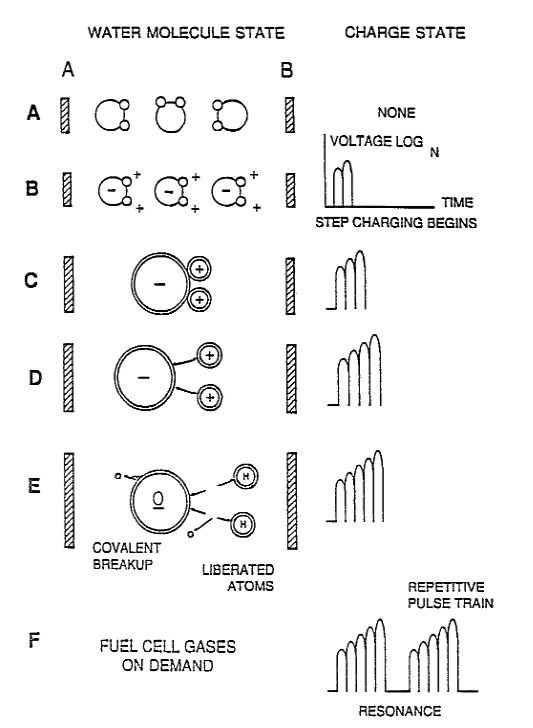
Figures 1A through 1F
Figures 1A through 1F are illustrations depicting the theoretical bases for phenomena encountered during operation of the fuel gas production stage of the invention herein
Figure 2 illustrates a circuit useful in the fuel gas generation process
Figure 2 - Useful Circuit
Figure 3 shows a perspective of a “water capacitor" element used in the fuel cell circuit.
Figure 3 - Perspective Water Capacitor Element
Figure 4 illustrates a staged arrangement of apparatus useful in the process, beginning with a water inlet and culminating in the production of thermal explosive energy.
Figure 4 - Staged Arrangement of Apparatus
Figure 5A shows a cross-section of a circular gas resonant cavity used in the final stage assembly of Figure 4.
Figure 5A - Gas Cavity Cross-Section
Figure 5B shows an alternative final stage injection system useful in the apparatus of Figure 4.
Figure 5B - Alternative Final Stage Injection System
Figure 5C shows an optical thermal lens assembly for use with either final stage of Figure 5A or Figure 53.
Figure 5C - Optical Thermal Lens Assembly
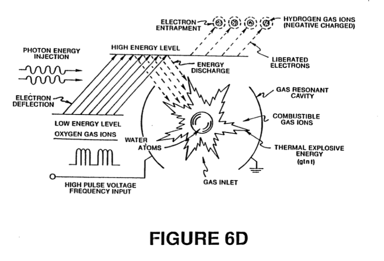
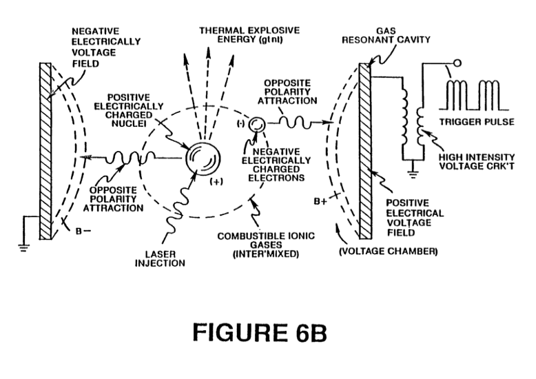
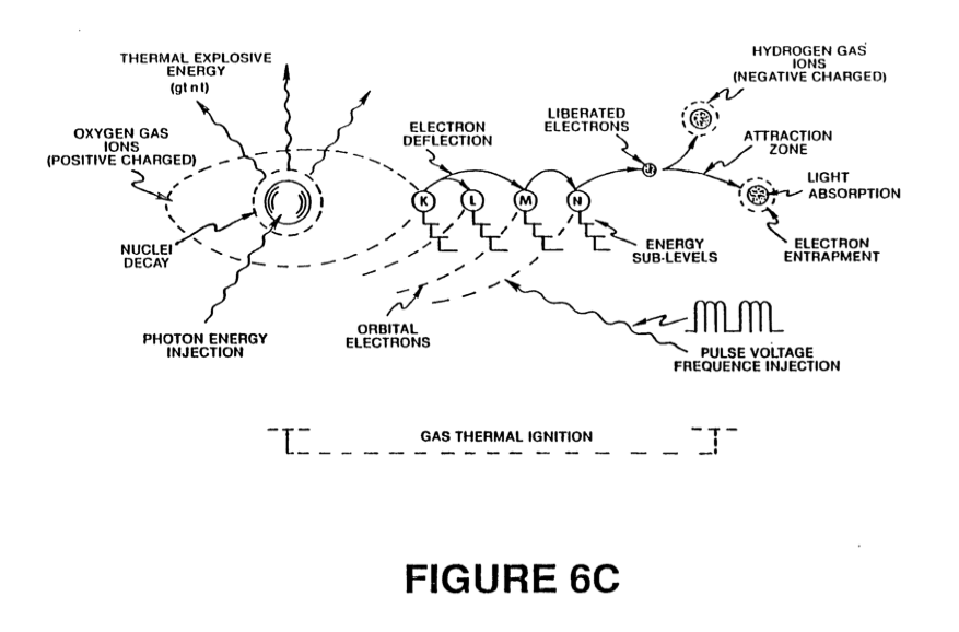
Figures 6A, 6B, 6C and 6D are illustrations depicting various theoretical bases for atomic phenomena expected to occur during operation of the invention herein.
Figures 6A, 6B, 6C and 6D - Various Theoretical Bases for Atomic Phenomena
|
|
|
|
|
|
Figure 7 is an electrical schematic of the voltage source for the Base resonant cavity.
Figure 7 - Base Voltage Source
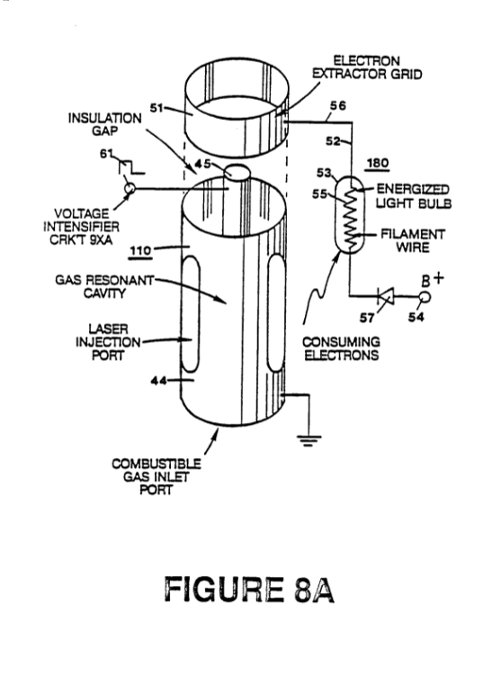
Figures 8A and 8B, respectively, show (A) an electron extractor grid used in the injector assemblies of Figure 5A and Figure 5B, and (B) the electronic control circuit for the extractor grid.
Figures 8A and 8B - Electron Extraction Grid & Control Circuit
|
|
 |
Figure 9 shows an alternate electrical circuit useful in providing a pulsating waveform to the apparatus.
Figure 9 - Alternate Pulse Waveform Circuit
Description of the Preferred Embodiment
A fuel gas is produced by a hydrogen fracturing process that follows the sequence of steps shown in the following Table I.
Beginning with water molecules, the molecule is subjected to successively increasing electrical wave energy and thermal forces. In the succession of forces, randomly oriented water molecules are aligned with respect to molecular polar orientation and are themselves polarized and “elongated” by the application of an electric potential to the extent that covalent bonding of the water molecule is so weakened that the atoms disassociate and the molecule breaks down into hydrogen and oxygen elemental components. The released atomic gases are next ionized and electrically charged in a vessel while being subjected to a further energy source that promotes inter-particle impact in the gas at an increased overall energy level. Finally, the atomic particles in the excited gas, having achieved successively higher energy levels, are subjected to a laser or electromagnetic wave energy source that produces atomic destabilization and the final release of thermal explosive energy. Engineering design parameters based on known theoretical principles of atomic physics determine the incremental levels of electrical and wave energy input required to produce resonance in each stage of the system. Instead of a dampening effect, a resonant energization of the molecule, atom or ion provides a compounding energy interaction resulting in the final energy release.
TABLE 1
PROCESS STEPS LEADING TO IGNITION
RELATIVE STATE OF WATER MOLECULE AND/OR HYDROGEN/OXYGEN/OTHER ATOMS
1st Stage Water to Gas
- RANDOM (AMBIENT STATE)
- ALIGNMENT OF POLAR FIELDS
- POLARIZATION OF MOLECULES
- MOLECULAR ELONGATION
- ATOM LIBERATION BY BREAKDOWN OF COVALENT BOND
- RELEASE OF GASES
2nd Stage Gas Ionization
- LIQUID TO GAS IONIZATION ELECTRICAL CHARGING EFFECT PARTICLE IMPACT
- ELECTROMAGNETIC WAVE, LASER OR PHOTON INJECTION
3rd Stage Priming
- ELECTRON EXTRACTION ATOMIC DESTABILIZATION
Final Stage Ignition
- THERMAL IGNITION
In brief, in the first stage a gas mixture including hydrogen and oxygen and other dissolved gases formerly entrapped in water is obtained, from water.
In general, the method used in the first stage consists of:
(A) providing a capacitor, in which the water is included as a dielectric liquid between capacitor plates, in a resonant charging choke circuit that includes an inductance in series with the capacitor;
(B) subjecting the capacitor to a pulsating, unipolar electric voltage field in which the polarity does not pass beyond an arbitrary ground, whereby the water molecules within the capacitor are subjected to a charge of the same polarity and the water molecules are distended by their subjection to electrical polar forces;
(C) further subjecting the water in said capacitor to said pulsating electric field to achieve a pulse frequency such that the pulsating electric field induces a resonance within the water molecule;
(D) continuing the application of the pulsing frequency to the capacitor cell after resonance occurs so that the energy level within the molecule is increased in cascading incremental steps in proportion to the number of pulses;
(E) maintaining the charge of said capacitor during the application of the pulsing field, whereby the covalent electrical bonding of the hydrogen and oxygen atoms within said molecules is destabilized such that the force of the electrical field applied, as the force is effective within the molecule, exceeds the bonding force of the molecule, and hydrogen and oxygen atoms are liberated from the molecule as elemental gases; and
(F) collecting said hydrogen and oxygen gases, and any other gases that were formerly dissolved within the water, and discharging the collected gases as a fuel gas mixture.
The water molecules are subjected to ‘increasing electrical forces. In an ambient state, randomly oriented water molecules are aligned with respect to a molecular polar orientation. They are next, themselves polarized and “elongated" by the application of an electric potential to the extent that covalent bonding of the water molecule is so weakened that the atoms disassociate and the molecule breaks down into hydrogen and oxygen elemental components.
In the process, the point of optimum gas release is reached at a circuit resonance.
Water in the fuel cell is subjected to a pulsating, polar electric field produced by the electrical circuit whereby the water molecules are distended by reason of their subjection to electrical polar forces of the capacitor plates. The polar pulsating frequency applied is such that the pulsating electric field induces a resonance in the molecule. A cascade effect occurs and the overall energy level of specific water molecules is increased in cascading, incremental steps. The hydrogen and oxygen atomic gases, and other gas components formerly entrapped as dissolved gases in water, are released when the resonant energy exceeds the covalent bonding force of the water molecule. A preferred construction material for the capacitor plates is a Stainless steel I-304 which is non-chemically reactive with water, hydrogen, or oxygen.
An electrically conductive material which is inert in the fluid environment is a desirable material of construction for the electrical field plates of the "water capacitor" employed in the circuit.
Once triggered, the gas output is controllable by the attenuation of operational parameters, Thus, once the frequency of resonance is identified, by varying the applied pulse voltage to the water fuel cell assembly, gas output is varied. By varying the pulse shape and/or amplitude or pulse train sequence of the initial pulsing wave source, final gas output is varied. Attenuation of the voltage field frequency in the form of OFF and ON pulses likewise affects output.
The overall apparatus thus includes an electrical circuit in which a water capacitor having a known dielectric property is an element. The fuel gases are obtained from the water by the disassociation of the water molecule. The water molecules are split into component atomic elements (hydrogen and oxygen gases) by a voltage stimulation process called the electrical polarization process which also releases dissolved gases entrapped in the water.
From the outline of physical phenomena associated with the first stage of the process described in Table 1, the theoretical basis of the invention considers the respective states of molecules and gases and ions derived from liquid water. Before voltage stimulation, water molecules are randomly dispersed throughout water within a container. When a uni-polar voltage pulse train such as shown in Figures 1B through 1F is applied to positive and negative capacitor plates, an increasing voltage potential is induced in the molecules in a linear, step-like charging effect. The electrical field of the particles within a volume of water including the electrical field plates increases from a low energy state to a high energy state successively in a step manner following each pulse-train as illustrated figuratively in the depictions of Figures 1A through 1F. The increasing voltage potential is always positive in direct relationship to negative ground potential during each pulse. The voltage polarity on the plates which create the voltage fields remains constant although the voltage charge increases. Positive and negative voltage “zones” are thus formed simultaneously in the electrical field of the capacitor plates.
In the first stage of the process described in Table 1, because the water molecule naturally exhibits opposite electrical fields in a relatively polar configuration (the two hydrogen atoms are positively electrically charged relative to the negative electrically charged oxygen atom), the voltage pulse causes initially randomly oriented water molecules in the liquid state to spin and orient themselves with reference to positive and negative poles of the voltage fields applied. The positive electrically charged hydrogen atoms of said water molecule are attracted to a negative voltage field; while, at the same time, the negative electrically charged oxygen atoms of the same water molecule are attracted to a positive voltage field. Even a slight potential difference applied to inert, conductive plates of a containment chamber which forms a capacitor will initiate polar atomic orientation within the water molecule based on polarity differences.
When the potential difference applied causes the orientated water molecules to align themselves between the conductive plates, pulsing causes the voltage field intensity to be increased in accordance with Figure 1B. As further molecular alignment occurs, molecular movement is hindered. Because the positively charged hydrogen atoms of said aligned molecules are attracted in a direction opposite to the negatively charged oxygen atoms, a polar charge alignment or distribution occurs within the molecules between said voltage zones, as shown in Figure 1B. And as the energy level of the atoms subjected to resonant pulsing increases, the stationary water molecules become elongated as shown in Figures 1C and 1D. Electrically charged nuclei and electrons are attracted toward opposite electrically charged voltage zones -- disrupting the mass and charge equilibrium of the water molecule.
Figures 1C and 1D - Step Charging 
As the water molecule is further exposed to an increasing potential difference resulting from the step charging of the capacitor, the electrical force of attraction of the atoms within the molecule to the capacitor plates of the chamber also increases in strength. As a result, the covalent bonding between atoms which form the molecule is weakened and ultimately terminated. The negatively charged electron is attracted toward the positively charged hydrogen atoms, while at the same time, the negatively charged oxygen atoms repel electrons.
In a more specific explanation of the "sub-atomic" action that occurs in the water cell that provides a fuel gas for the subsequent stages, it is known that natural water is a liquid which has a dielectric constant of 78.54 at 20°C and 1 atm pressure.
Source: [Handbook of Chemistry and Physics, 68th ed., CRC Press (Boca Raton, Florida (1987-88)), Section E-50, H20 (water)].
When a volume of water is isolated and electrically conductive plates, that are chemically inert in water and are separated by a distance, are immersed in the water, a capacitor is formed, having a capacitance determined by the surface area of the plates, the distance of their separation and the dielectric constant of water.
When water molecules are exposed to voltage at a restricted current, water takes on an electrical charge. By the laws of electrical attraction, molecules align according to positive and negative polarity fields of the molecule and the alignment field. The plates of a capacitor constitute such an alignment field when a voltage is applied.
When a charge is applied to a capacitor, the electrical charge of the capacitor equals the applied voltage charge; in a water capacitor, the dielectric property of water resists the flow of amps in the circuit, and the water molecule itself, because it has polarity fields formed by the relationship of hydrogen and oxygen in the covalent bond, and an intrinsic dielectric property, becomes part of the electrical circuit, analogous to a "micro-capacitor" within the capacitor defined by the plates.
In the Example of a fuel cell circuit of Figure 2, a water capacitor is included. The step-up coil is formed on a conventional torroidal core formed of a compressed ferromagnetic powdered material that will not itself become permanently magnetized, such as the trademarked "Ferramic 06# "Permag" powder as described in Siemens Ferrites Catalog, CG~2000-002-121, (Cleveland, Ohio) No. F626-1205. The core is 1.50 inch in diameter and .25 inch in thickness. A primary coil of 200 turns of ~6-gauge copper wire is provided and a coil of 600 turns of 36 gauge wire comprises the secondary winding. Other primary/secondary coil winding ratios may be conventionally determined.
An alternate coil arrangement using a conventional M27 iron transformer core is shown in Figure 9. The coil wrap is always in one direction only.
In the circuit of Figure 2, the diode is a 1N1198 diode which acts as a blocking diode and an electric switch that allows voltage flow in one direction: only. Thus, the capacitor is never subjected to a pulse of reverse polarity.
The primary coil of the toroid is subject to a 50% duty cycle pulse. The toroidal pulsing coil provides a voltage step-up from the pulse generator in excess of five times, although the relative amount of step-up is determined by pre-selected criteria for a particular application. As the stepped-up pulse enters first inductor (formed from 100 turns of 24 gauge wire 1 inch in diameter), an electromagnetic field is formed around the inductor, voltage is switched off when the pulse ends, and the field collapses and produces another pulse of the same polarity; i.e., another positive pulse is formed where the 50% duty cycle was terminated. Thus, a double pulse frequency is produced; however, in a pulse train of uni-polar pulses, there is a brief time when pulses are not. present.
By being so subjected to electrical pulses in the circuit of Figure 2, water confined in the volume that includes the capacitor plates takes on an electrical charge that is increased by a step charging phenomenon occurring in the water capacitor.
Voltage continually increases (to about 1000 volts and more) and the water molecule starts to elongate.
The pulse train is then switched off: the voltage across the water capacitor drops to the amount of charge that the water molecules have taken on, i.e. voltage is maintained across the charged capacitor. The pulse train is then reapplied.
Because a voltage potential applied to a capacitor can perform work, the higher the voltage potential, the more work is performed by a given capacitor. In an optimum capacitor that is wholly non-conductive, zero (0) current flow will occur across the capacitor. Thus, in view of an idealized capacitor circuit, the object of the water capacitor circuit is to prevent electron flow through the circuit, i.e. such as occurs by electron flow or leakage through a resistive element that produces heat. Electrical leakage in water will occur, however, because of some residual conductivity and impurities or ions that may be otherwise present in the water. Thus, the water capacitor is preferably chemically inert. An electrolyte is not added to the water.
In the isolated water bath, the water molecule takes on charge, and the charge increases. The object of the process is to switch off the covalent bonding of the water molecule and interrupt the sub-atomic force, i.e, the electrical force or electromagnetic force, that binds the hydrogen and oxygen atoms to form a molecule so that the hydrogen and oxygen separate.
Because an electron will only occupy a certain electron shell (the shells are well known) the voltage applied to the capacitor affects the electrical forces inherent in the covalent bond. As a result of the charge applied by the plates, the applied force becomes greater than the force of the covalent bonds between the atom of the water molecule; and the water molecule becomes elongated. When this happens, the time share ratio of the electrons between the atoms and the electron shells is modified.
In the process, electrons are extracted from the water bath; electrons are not consumed nor are electrons introduced into the water bath by the circuit as electrons are conventionally introduced in an electrolysis process. There may nevertheless occur a leakage current through the water. Those hydrogen atoms missing electrons become neutralized; and atoms are liberated from the water. The charged atoms and electrons are attracted to opposite polarity voltage zones created between the capacitor plates. The electrons formerly shared by atoms in the water covalent bond are re-allocated such that neutral elemental gases are liberated.
In the process, the electrical resonance may be reached at all levels of voltage potential. The overall circuit is characterized as a "resonant charging choke" circuit which is an inductor in series with a capacitor that produces a resonant circuit.
Source: [SAMS Modern Dictionary of Electronics, Rudolff Garff, ©1984, Howard W. Sams & Co. (Indianapolis, Ind.)}, page 859.]
Such a resonant charging choke is on each side of the capacitor. In the circuit, the diode acts as a switch that allows the magnetic field produced in the inductor to collapse, thereby doubling the pulse frequency and preventing the capacitor from discharging. In this Manner a continuous voltage is produced across the capacitor plates in the water bath; and the capacitor does not discharge. The water molecules are thus subjected to a continuously charged field until the breakdown of the covalent bond occurs,
As noted initially, the capacitance depends on the dielectric properties of the water and the size and separation of the conductive elements forming the water capacitor.
EXAMPLE I
In an example of the circuit of Figure 2 (in which other circuit element specifications are provided above), two concentric cylinders 4 inches long formed the water capacitor of the fuel cell in the volume of water. The outside cylinder was 0.75 inch in outside diameter; the inner cylinder was 0.5 inch in outside diameter. Spacing from the outside of the inner cylinder to the inner surface of the outside cylinder was .0625 inch. Resonance in the circuit was achieved at a 26 volt applied pulse to the primary coil of the toroid at 10KHz, and the water molecules disassociated into elemental hydrogen and oxygen and the gas released from the fuel cell comprised a mixture of hydrogen, oxygen from the water molecule, and gases formerly dissolved in the water such as the atmospheric gases or oxygen, nitrogen, and argon. In achieving resonance in any circuit, as the pulse frequency is adjusted, the flow of amps is minimized and voltage is maximized to a peak. Calculation of the resonance frequency of an overall circuit is determined by known means; different cavities have a different frequency of resonance dependent on parameters of the water dielectric, plate size, configuration and distance, circuit inductors, and the like. Control of the production of fuel gas is determined by variation of the period of time between a train of pulses, pulse amplitude and capacitor plate size and configuration, with corresponding value adjustments to other circuit components.
The wiper arm on the second inductor tunes the circuit and accommodates to contaminants in water so that the charge is always applied to the capacitor. The voltage applied determines the rate of breakdown of the molecule into its atomic components. As water in the cell is consumed, it is replaced by any appropriate means or control system.
Thus in the first stage, which is of itself independently useful, a fuel gas mixture is produced having, in general, the components of elemental hydrogen and oxygen as well as formerly dissolved entrapped atmospheric gases such as nitrogen, argon, and the like. The fuel gas is itself combustible in a conventional manner. .
After the first stage the gas atoms become elongated during electron removal as the atoms are ionized. Laser, or light wave energy of a predetermined frequency is injected into a containment vessel in a gas ionization process. The light energy absorbed by voltage stimulated gas nuclei causes destabilization of gas ions still further. The absorbed laser energy causes the gas nuclei to increase in energy state, which, in turn, causes electron deflection to a higher orbital shell.
The electrically charged and laser primed combustible gas ions from a gas resonant cavity may be directed into an optical thermal liens assembly for triggering. Before entry into the optimal thermal lens, however, electrons are stripped from the ions and the atom is destabilized. The destabilized gas ions which are electrically and mass unbalanced atoms having highly energized nuclei are pressurized during spark ignition. The unbalanced, destabilized atomic components thermally interact; the energized and unstable hydrogen gas nuclei collide with highly energized and unstable oxygen gas nuclei, causing and producing thermal explosive energy beyond the gas burning Stage. The ambient air gas components in the initial mixture aid the thermal explosive process under a controlled state,
In the process, the point of optimum energy-yield is reached when the electron deficient oxygen atoms (having less than a normal number of electrons) lock onto and capture a hydrogen atom electron prior to or during thermal combustion of the hydrogen/oxygen mixture, Atomic decay results in the release of energy.
After the first stage, the gas mixture is subjected to a pulsating, polar electric field whereby electrons of the gas atoms are distended in their orbital fields by reason of their subjection to electrical polar forces. The polar pulsating frequency applied is such that the pulsating electric field induces a resonance with respect to an electron of the gas atom. A cascade effect results and the energy level of. specific resonating electron is increased in cascading, incremental steps.
Next, the gas atoms are ionized and subjected to electromagnetic wave energy having a predetermined frequency to induce a further election resonance in the ion, whereby the energy level of the election is successively increased. Electrons are extracted from the resonating ions while such ions are in an increased energy State to destabilize the nuclear electron configuration of said ions; and the gas mixture of destabilized ions is thermally ignited.
In the apparatus shown in Figure 4, water is introduced at inlet 1 into a first stage water fracturing module 2, such as the water fuel cell described above, in which water molecules are broken down into hydrogen, oxygen and released entrapped gas components. The released atomic gases and other gas components formerly entrapped as dissolved gases in water may be introduced to a successive stage 3 or other number of like resonant cavities, which are arranged in either a series or parallel combined array. The successive energization of the gas atoms provides a cascading effect, successively increasing the voltage stimulation level of the released gasses as they sequentially pass through cavities 2, 3, etc. Ina final stage, an injector system 4, of a configuration of the type show in Figures 5A or 5B, receives energized atomic and gas particles where the particles are subjected to further energy input, electrical excitation and thermal stimulation, whereby thermal explosive energy results 5, which may be directed thru a lens assembly of the type shown in Figure 5C to provide a controlled thermal energy output.
A single cell, or a battery of cells such as shown in Figure 3, provides a fuel gas source for stages after the first stage. The fuel gas is activated by electromagnetic waves, and electrically charged gas ions of hydrogen and oxygen (of opposite polarity) are expelled from the cascaded cells 2, 3, etc. shown in Figure 4. The circuit of Figure 9 may be utilized as a source of ionizing energy for the gases. The effect of cascading successively increases the voltage stimulation level of the released gases, which then are directed to the final injector assembly 4. In the injector assembly, gas ions are stimulated to a yet higher energy level. The gases are continually exposed to a pulsating laser or other electromagnetic wave energy source together with a high intensity oscillating voltage field that occurs within the cell between electrodes or conductive plates of opposite electrical polarity. A preferred construction material for the plates is a stainless steel T-304 which is non-chemically reactive with water, hydrogen, or oxygen. An electrically conductive material which is inert in the fluid environment is a desirable material of construction for the electrical field producing plates, through which field the gas stream of activated particles passes. Gas ions of opposite electrical charges reach and maintain a critical energy level state. The gas ions are oppositely electrically charged and subjected to oscillating voltage fields of opposite polarity and are also subjected to a pulsating electromagnetic wave energy source. Immediately after reaching critical energy, the excited gas ions are exposed to a high temperature thermal zone in the injection cell, 4, that causes the excited gas ions to undergo gas combustion. The gas ignition triggers atomic decay and releases thermal energy, 5, with explosive force.
Once triggered, the thermal explosive energy output is controllable by the attenuation of operational parameters. With reference to Figure 6A, for example, once the frequency of resonance is identified, by varying applied pulse voltage to the initial water fuel cell assemblies, 2, 3, the ultimate explosive energy output is likewise varied. By varying the pulse shape and/or amplitude or pulse train sequence of the electromagnetic wave energy source, final output is varied. Attenuation of the voltage field frequency in the form of OFF and ON pulses likewise affects output of the staged apparatus. Each control mechanism can be used separately, grouped in sections, or systematically arranged in a sequential manner.
A complete system in accordance with the present application thus includes a water fuel cell for providing a first fuel gas mixture consisting of at least a portion of hydrogen and oxygen gas. An electrical circuit of the type shown in Figure 7 provides a pulsating, polar electric field to the gas mixture as illustrated in Figure 6A, whereby electrons of the gas atoms are distended in their orbital fields by reason of their subjection to electrical polar forces, changing from the state conceptually illustrated by Figures 6B to that of Figure 6G, at a frequency such that the pulsating electric field induces a resonance with respect to electrons of the gas atoms. The energy level of the resonant electrons is thereby increased in cascading, incremental steps. A further electric field to ionize said gas atoms is applied and an electromagnetic wave energy source for subjecting the ionized gas atoms to wave energy of a predetermined frequency to induce a further electron resonance in the ion, whereby the energy level of the election is successively increased is an additional element of the apparatus as shown in Figure 6D.
|
 |
An electron sink, which may be in the form of the grid element shown in Figure 8A, extracts further electrons from the resonating ions. While such ions are in an increased energy state and destabilizes the nuclear electron configuration of the ions. The "extraction" of electrons by the sink means is coordinated with the pulsating electrical field of the resonant cavity produced by the circuit of Figure 7, by means of an interconnected synchronization circuit, such as shown in Figure 8B. A nozzle, 10 in Figure 5B, or thermal lens assembly, Figure 5C, provides the directing means in which the destabilized ions are finally thermally ignited.
 |
|
As previously noted, to reach and trigger the ultimate atomic decay of the fuel cell gases at the final stage, sequential steps are taken, First, water molecules are split into component atomic elements (hydrogen and oxygen gases) by a voltage stimulation process which also releases dissolved gases entrapped in the water. In the injector assembly, a laser produced light wave or other form of coherent electromagnetic wave energy capable of stimulating a resonance within the atomic components is absorbed by the mixture of gases (hydrogen/oxygen/ambient air gases) released by the polarization process. At this point, as shown in Figure 6B, the individual atoms are subjected to an electric field to begin an ionization process.
The laser or electromagnetic wave energy is absorbed and causes gas atoms to lose electrons and form positively charged gas ions. The energized hydrogen atoms which, as ionized, are positively charged, now accept electrons liberated from the heavier gases and attract other negatively charged gas ions as conceptually illustrated in Figure 6C. Positively and negatively charged gas ions are re-exposed to further pulsating energy sources to maintain random distribution of ionized atomic gas particles.
The gas ions within the wave energy chamber are subjected to an oscillating high intensity voltage field in a chamber 11 in Figures 5A and 5B formed within electrodes 12 and 13 in Figures 5A and 5B of opposite electrical polarity to produce a resonant cavity. The gas ions reach a critical energy state at a resonant state,
|
|
At this point, within the chamber, additional electrons are attracted to said positive electrode; whereas, positively charged ions or atomic nuclei are attracted to the negative electrode. The positive and negative attraction forces are co-ordinate and operate on said gas ions simultaneously; the attraction forces are non-reversible. The gas ions experience atomic component deflection approaching the point of electron Separation. At this point electrons are extracted from the chamber by a grid system such as shown in Figure 5A. The extracted electrons are consumed and prevented from re-entering the chamber by a circuit such as shown in Figure 8B. The elongated gas ions are subjected to a thermal heat zone to cause gas ignition, releasing thermal energy with explosive force. During ionic gas combustion, highly energized and stimulated atoms and atom nuclei collide and explode during thermal excitation. The hydrogen fracturing process occurring sustains and maintains a thermal zone, at a temperature in excess of normal hydrogen/oxygen combustion temperature, to wit, in excess of 2500°F. To cause and maintain atomic elongation depicted in Figure 6C before gas ignition, a voltage intensifier circuit such as shown in Figure 7 is utilized as a current restricting voltage source to provide the excitation voltage applied to the resonant cavity. At the same time the interconnected electron extractor circuit, Figure 8B, prevents the reintroduction of electrons back into the system. Depending on calculated design parameters, a predetermined voltage and frequency range may be designed for any particular application or physical configuration of the apparatus.
In the operation of the assembly, the pulse train source for the gas resonant cavity shown at 2 and 3 in Figure 4 may be derived from a circuit such as shown in Figures 2, 7 or 9, and such cavity circuits may be in sequence to provide a cascading energy input. It is necessary in the final electron extraction that the frequency with which electrons are removed from the system by sequenced and synchronized with the pulsing of the gas resonant cavity. In the circuit of Figure 8B, the coordination or synchronization of the circuit with the circuit of Figure 7 may be achieved by interconnecting point "A" of the gate circuit of Figure 8B to coordinate point "A" of the pulsing circuit of Figure 7.
|
|
|
The circuit shown in Figure 9 enhances the voltage potential across the resonant charging choke coils during puising operations and restricts amp flow by allowing an external electromagnetic pulsing field, F, derived from the primary coil A being energized to transverse the coil windings D and E being energized by the incoming pulse train Ha xxx Hn, through switching diode G, The external pulse field, F and the incoming pulse-train Ha xxx Hn, are sequentially the same, allowing resonant action to occur, restricting amp flow while allowing voltage intensity to increase to stimulate the electrical polarization process, the gas ionization process and the electron extraction process. The voltage intensifier circuit of Figure 9 prevents electrons from entering into those processes.
Together, the hydrogen injector assembly 4 and the resonant cavity assemblies 2, 3 form a gas injector fuel cell which is compact, light in weight and design variable. For example, the hydrogen injector system is suited for automobiles and jet engines. Industrial applications require larger systems. For rocket engine applications, the hydrogen gas injector system is positioned at the top of each resonant cavity arranged in a parallel cluster array. If resonant cavities are sequentially combined in a parallel/series array, the hydrogen injection assembly is positioned after the exits of said resonant cavities are combined.
From the outline of physical phenomena associated with the process described in Table 1, the theoretical basis of the invention considers the respective states of molecules, gases and ions derived from liquid water. Before voltage stimulation, water molecules are randomly dispersed throughout water within a container. When a uni-polar voltage pulse train such as shown in Figure 6A (53a xxx 53n) is applied, an increasing voltage potential is induced in the molecules, gases and/or ions in a linear, step-like charging effect. The electrical field of the particles within a chamber including the electrical field plates increases from a low energy state (A) to a high energy state (J) in a step manner following each pulse-train as illustrated in Figure 6A. The increasing voltage potential is always positive in direct relationship to negative ground potential during each pulse. The voltage polarity on the plates which create the voltage fields remains constant. Positive and negative voltage "zones" are thus formed simultaneously.

In the first stage of the process described in Table 1, because the water molecule naturally exhibits opposite electrical fields in a relatively polar configuration (the two hydrogen atoms are positively electrically charged relative to the negative electrically charged oxgen atom), the voltage pulse causes initially randomly oriented water molecules in the liquid state to spin and orient themselves with reference to positive and negative poles of the voltage fields applied. ‘The positive electrically charged hydrogen atoms of said water molecule are attracted to a negative voltage field; while, at the same time, the negative electrically charged oxygen atoms of the same water molecule are attracted to a positive voltage field. Even a slight potential difference applied to the inert, conductive plates of a containment chamber will initiate polar atomic orientation within the water molecule based on polarity differences,
When the potential difference applied causes the orientated water molecules to align themselves between the conductive plates, pulsing causes the voltage field intensity to be increased in accordance with Figure 6A. As further molecular alignment occurs, molecular movement is hindered, Because the positively charged hydrogen atoms of said aligned molecules are attracted in a direction opposite to the negatively charged oxygen atoms , a4 polar charge alignment or distribution occurs within the molecules between said voltage zones, as shown in Figure 6B. And as the energy level of the atoms subjected to resonant pulsing increases, the stationary water molecules become elongated as shown in Figure 6C. Electrically charged nuclei and electrons are attracted toward opposite electrically charged voltage zones ~— disrupting the mass equilibium of the water molecule.
In the first stage, as the water molecule is further exposed to a potential difference, the electrical force of attraction of the atoms within the molecule to the electrodes of the chamber also increases in intensity. As a result, the covalent bonding between said atoms which forms the molecule is weakened and ultimately terminated. The negatively charged electron is attracted toward the positively charged hydrogen atoms ’ while at the same time, the negatively charged oxygen atoms repel electrons,
Once the applied resonant energy caused by pulsation of the electrical field in the cavities reaches a threshold level, the disassociated water molecules, now in the form of liberated hydrogen, oxygen, and ambient air gases begin to ionize and lose or gain electrons during the final stage in the injector assembly. Atom destabilization occurs and the electrical and mass equilibrium of the atoms is disrupted. Again, the positive field produced within the chamber or cavity that encompasses the gas steam attracts negatively charged ions while the positively charged ions (and/or hydrogen nuclei) are attracted to the negative field. Atom stabilization does not occur because the pulsating voltage applied is repetitive without polarity change. A potential of approximately several thousand volts triggers the ionization state,
As the ionized particles accumulate within said chamber, the electrical charging effect is again an incremental stepping effect that produces an accumulative increased potential while, at the same time, resonance occurs.
The components of the atom begin to "vibrate" at a resonant frequency such that an atomic instability is created. As shown in Figure 6D, a high energy level is achieved, which then collapses resulting in the release of thermal explosive energy. Particle impact occurs when liberated ions in a gas are subjected to further voltage. A longitudinal cross section of a gas resonant cavity is shown in Figure 5A. To promote gas ionization, electromagnetic wave energy such as a laser or photon energy source of a predetermined wave length and pulse-intensity is directed to and absorbed by the ions forming said gas. In the device of Figure 5A, semiconductor optical lasers 20a-20p, 20xxx surround the gas flow path. In the device of Figure 5B, photon energy 20 is injected into a separate absorption chamber 21. The incremental stimulation of nuclei to a more highly energized state by electromagnetic wave energy causes electron deflection to a higher orbital state. The pulse rate as well as intensity of the electromagnetic wave source is varied to match the absorption rate of ionized particles to produce the stepped incremental increase in energy. A single laser coupled by means of fiber optic light guides is an alternative to the plurality of lasers shown in Figure 5B. Continued exposure of the gas ions to different forms of wave energy during voltage stimulation maintains individual atoms in a destabilized state and prevents atomic stabilization.
|
|
The highly energized gas ions are thermally ignited when said combustible gas ions pass from injector 4 and enter into and pass through a nozzle, 10 in Figure 5B, or an optical thermal lens assembly such as shown in Figure 5C, In Figure 5C, the combustible gas ions are expelled through and beyond a quenching circuit, 30, and reflected by lenses, 31 and 32, back and forth through a thermal heat zone, 33, prior to atomic breakdown beyond exiting through a final port, 34. A quenching circuit is a restricted orifice through which the particle stream passes such that flashback does not occur. The deflection shield or lens, 31, superheats beyond 3,000° F. and the combustible gas ions passing through said exiting-ports are regulated to allow a gas pressure to form inside said thermal zone. The energy yield is controlled by varying the applied voltage, or pulse-train since said thermal-lens assembly is self-adjusting to the flow-rate of said ionized and primed gases. The combustible ionic gas mixture is composed of hydrogen, oxygen, and ambient air gases. The hydrogen gas provides the thermal explosive force, the oxygen atoms aid the gas thermal ignition, and the ambient air gases retard the gas thermal ignition process to a controllable state. As the combustible gas mixture is exposed to a voltage pulse train, the stepped increasing voltage potential causes said moving gas atoms to become ionized (losing or gaining electrons) and changes the electrical and mass equilibrium of said atoms. Gases that do not wndergo the gas ionization process may accept the liberated electrons (electron entrapment) when exposed to light or photon stimulation. The electron extractor grid circuit, Figures 8A and 8B, is applied to the assembly of Figure 5A or Figure 5B, and restricts electron replacement. The extractor grid, 56, is applied adjacent to electric field producing members, 44 and 45, within the resonant cavity. The gas ions incrementally reach a critical-state which occurs after a high energy resonant state. At this point the atoms no longer tolerate the missing electrons, the unbalanced electrical field, and the energy stored in the nucleus. Immediate collapse of the system occurs and energy is released as the atoms decay into thermal explosive energy.
The repetitive application of a voltage pulse train (A through J of Figure 6A) incrementally achieves the critical state of said gas ions. As the gas atoms or ions (la xxx in) shown in Figure 6C become elongated during electron removal, electromagnetic wave energy of a predetermined frequency and intensity is injected. The wave energy absorbed by the stimulated gas nuclei and electrons causes further destabilization of the ionic gas. The absorbed energy from all sources causes the gas nuclei to increase in energy state, and induces the ejection of electrons from the nuclei,
To further stimulate the electron entrapment process beyond the atomic level (capturing the liberated electrons during the hydrogen fracturing process) the electron extractor grid (as shown in Figure 8A) is placed in spaced relationship to the gas resonant cavity structure shown in Figure 5A. The electron extractor grid is attached to an electrical circuit (such as shown in Figure 8B) that allows electrons to flow to an electrical load, 55, when a positive electrical potential is placed on the opposite side of said electrical load. The electrical load may be a typical power consuming device such as a light bulb or resistive heat. producing device. As the positive electrical potential is switched on or pulse-applied, the negative charged electrons liberated in the gas resonant cavity are drawn away and enter into resistive load where they are consumed and released as heat or light energy. The consuming electrical circuit can be directly connected to the gas resonant cavity positive electrical voltage zone. The incoming positive wave form applied to resonant cavity voltage zone through a blocking diode is synchronized with the pulse train applied to the gas resonant cavity by the circuit of Figure 7 via alternate gate circuit. As one pulse train is gated “ON,” the other pulse train is switched "OFF." A blocking diode directs the electron flow to said electrical load while resistive wire prevents voltage leakage during pulse train "ON" time.
The electron extraction process is maintained during gas flow-rate change by varying the trigger pulse rate in relationship to applied voltage. The electron extraction process also prevents spark-ignition of the combustible gases traveling through the gas resonant cavity because electron build-up and potential sparking is prevented.
In an optical thermal lens assembly or thrust-nozzle, such as shown in Figure 5C, destabilized gas ions (electrically and mass unbalanced gas atoms having highly energized nuclei) can he pressurized during spark-ignition, During thermal interaction, the highly energized and unstable hydrogen gas nuclei collide with the highly energized and unstable oxygen gas nuclei and produce thermal explosive energy beyond the gas burning stage. Other ambient air gases and ions not otherwise consumed limit the thermal explosive process.
Variations of the process and apparatus may be evident to those skilled in the art.
WHAT IS CLAIMED IS:
1. A method of obtaining the release of a gas mixture including hydrogen and other dissolved gases entrapped in water, from water, consisting of:
(A) providing a capacitor, in which the water is included as a dielectric between capacitor plates, in a resonant charging choke circuit that includes an inductance in series with the capacitor;
(B) subjecting the capacitor to a pulsating, uni-polar electric field in which the polarity does not pass beyond an arbitrary ground, whereby the water molecules within the capacitor are subjected to a charge of the same polarity;
(C) further subjecting the water in said capacitor to said pulsating electric field to achieve a pulse frequency such that the pulsating electric field induces a resonance within the water molecule;
(D) continuing the application of the pulsing frequency to the capacitor after resonance occurs so that the energy level within the molecule is increased in cascading incremental steps in proportion to the number of pulses;
(E) maintaining the charge of said capacitor during the application of the pulsing field, whereby the covalent electrical bonding of the hydrogen and oxygen atoms within said molecules is destabilized, such that the force of the electrical field applied within the molecule exceeds the bonding force of the molecule, and hydrogen and oxygen atoms are liberated from the molecule as elemental gases; and
(F) collecting said hydrogen and oxygen gases, and any other gases that were formerly dissolved within the water and discharging said collected gases as a fuel gas mixture.
2. The method of claim 1 including the further steps of:
(A) subjecting the collected gas mixture to a pulsating, polar electric field whereby electrons of the gas atoms are distended in their orbital fields by reason of their subjection to electrical polar forces, at a frequency such that the pulsating electric field induces a resonance with respect to an electron of the gas atom;
(B) cascading said gas atoms with respect to the pulsating electric field such that the energy level of the resonant electron is increased in cascading incremental steps;
(C) ionizing said gas atoms;
(D) subjecting the ionized gas atoms to electromagnetic wave energy having a predetermined frequency to induce a further election resonance in the ion, whereby the energy level of the electron is successively increased;
(E) extracting further electrons from the resonating ions while such ions are in an increased energy state to destabilize the nuclear and electron configuration of said ions; and
(F) subjecting the destabilized ions to thermal ignition, whereby thermal energy having a level enhanced over conventional combustion is achieved
3. In an apparatus for obtaining the release of a gas mixture including hydrogen and other dissolved gases entrapped in water, from water, the improvement consisting of a resonant electronic circuit in operative relationship with the water in which the dielectric property of water determines the resonance of the circuit.
4. The apparatus of Claim 3 in which the resonant circuit includes a resonant charging choke.
5. The apparatus of Claim 3 or Claim 4 in which water is included as a dielectric between conductive plates that form a capacitor in the resonant circuit.
6. An apparatus in accordance with Claim 3 or Claim 4 or Claim 5 further including successively interconnected:
(A) means for providing a pulsating, polar electric field to the gas mixture, whereby electrons of the gas atoms are- distended in their orbital fields by reason of their subjection to electrical polar forces, at a frequency such that the pulsating electric field induces a resonance with respect to an electron of the. gas atom; and the energy level of the resonant electron is increased in cascading, incremental steps; and
(B) means for providing a further electric field to ionize said gas atoms;
said further means connected to an electromagnetic wave energy source for subjecting the ionized gas atoms to wave energy of a predetermined frequency to induce a further election resonance in the ion, whereby the energy level of the electron is further successively increased; and
(C) an electron sink for extracting electrons from the resonating ions while such ions are in an increased energy state to destabilize the nuclear and electron configuration of said ions;
(D) a control means for directing particle flow in a continuous manner through the electric fields, wave energy source and electron sink to a final orifice at which the destabilized ions are thermally ignited; and
(E) a terminal orifice at which the mixture initially provided by the first means, after having passed through and been processed by the preceding means of the apparatus, is thermally ignited.
7. The method and apparatus as substantially described herein.
WO9222679A1 - Water Fuel Injection System
PDF Download: SMeyer-WO9222679A1-Water_Fuel_Injection_System.pdf
PCT WORLD INTELLECTUAL PROPERTY ORGANIZATION International Bureau
INTERNATIONAL APPLICATION PUBLISHED UNDER THE PATENT COOPERATION TREATY (PCT)
(51) International Patent Classification 5 : (11) International Publication Number: WO 92/22679 B Al oe te ete 51/00 (43) International Publication Date: © 23 December 1992 (23.12.92) (21) International Application Number: PCT/US91/03476 | Published
With international search report. (22) International Filing Date: 12 June 1991 (12.06.91)
(71}{(72) Applicant and Inventor: MEYER, Stanley, A. [US/US]; 3792 Broadway Blvd., Grove City, OH 43123 (US).
(74) Agent: BARANOWSKI, Edwin, M.; Porter, Wright, Mor- ris & Arthur, 41 South High Street, Columbus, OH 43215 (US).
(81) Designated States: AT (European patent), AU, BE (Euro- pean patent), CA, CH (European patent), DE (European patent), DK (European patent), ES (European patent), FR (European patent), GB (European patent), GR (Eu- ropean patent), IT (European patent), JP, KR, LU (Euro- pean patent), NL (Buropean patent), SE (European pa- tent), US.
(57) Abstract
An injector system comprising an improved method and apparatus useful in the production of a hydrogen containing fuel gas from water in a process in which the dielectric property of water and/or a mixture of water and other components determines a resonant condition that produces a breakdown of the atomic bonding of atoms in the water molecule. The injector delivers a mixture of water mist (1), ionized gases (2), and non-combustible gas (3) to a zone or locus (5) within which the breakdown pro- cess leading to the release of elemental hydrogen from the water molecules occurs.
WATER FUEL INJECTION SYSTEM
This invention relates to a method and apparatus useful in producing thermal combustive energy from the hydrogen component of water.
In my patent no. 4,936,961, "Method for the Production of a Fuel Gas," I describe a water fuel cell which produces a gas energy source by a method that utilizes water as a dielectric component of a resonant electrical circuit.
In my patent no. 4,826,581, "Controlled Process for the Production of Thermal Energy From Gases and Apparatus Useful Therefore,” I describe a method and apparatus for obtaining the enhanced release of thermal energy from a gas mixture including hydrogen and oxygen in which the gas is subjected to various electrical, ionizing and electromagnetic fields.
In my co-pending application serial no. 07/460,859, “Process and Apparatus for the Production of Fuel Gas and the Enhanced Release of Thermal Energy from Fuel Gas," I describe various means and methods for obtaining the release of thermal/combustive energy from the hydrogen (H) component of a fuel gas obtained from the disassociation of a water (HzO) molecule by a process which utilizes the dielectric properties of water in a resonant circuit; and in that application I more thoroughly describe the physical dynamics and chemical aspects of the water-to-fuel conversion process.
The invention of this present application represents a generational improvement in methods and apparatus useful in the utilization of water as a fuel source. In brief, the present invention is a micro-miniaturized water fuel cell and permits the direct injection of water, and its simultaneous transformation into a hydrogen containing fuel, in a combustion zone, such as a cylinder in an internal combustion engine, a jet engine, or furnace. Alternatively the injection system of the present invention may be utilized in any non-engine application in which a concentrated flame or heat source is desired, for example, welding.
The present injection system eliminates the need for an enclosed gas pressure vessel in a hydrogen fuel system and thereby reduces a potential physical hazard heretofore associated with the use of hydrogen-based fuels. The system produces fuel on demand in real-time operation and sets up an integrated environment of optimum parameters so that a water-to-fuel conversion process works at high efficiency.
The preferred embodiment of the invention is more fully explained below with reference to the drawings in which:
Figure 1 figuratively illustrates the sections and operating zones included in a single injector of the invention.
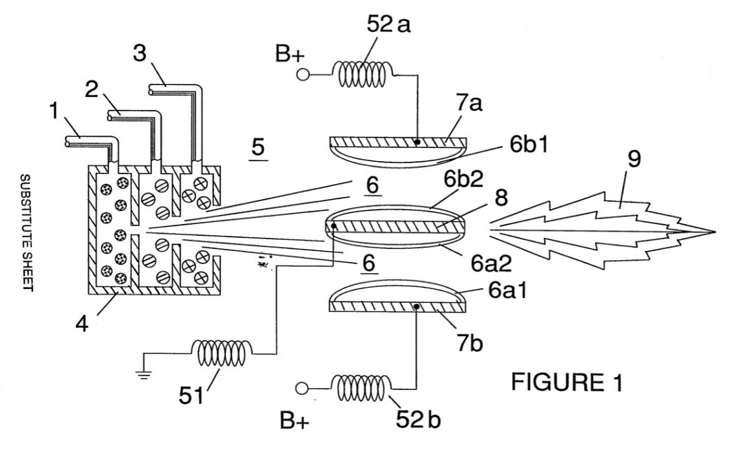
Figure 2A is a side cross sectional view; Figure 2B is a frontal view from the operative end; and Figure 2c is an exploded view -- of an individual injector.
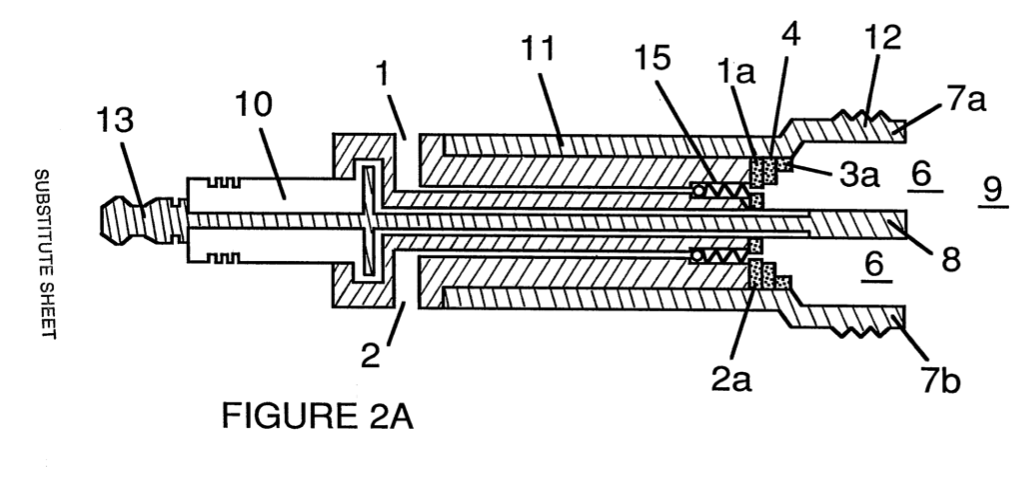 |
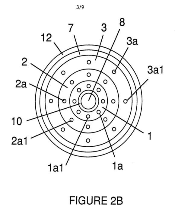 |
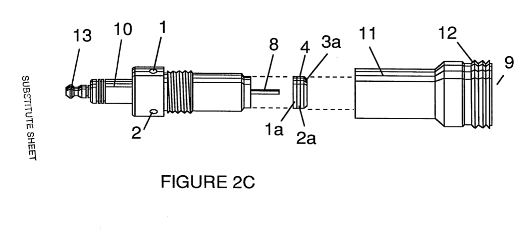
Figure 3A and Figure 3B respectively show a side cross-section view and frontal view of an alternatively configured injector.
|
|
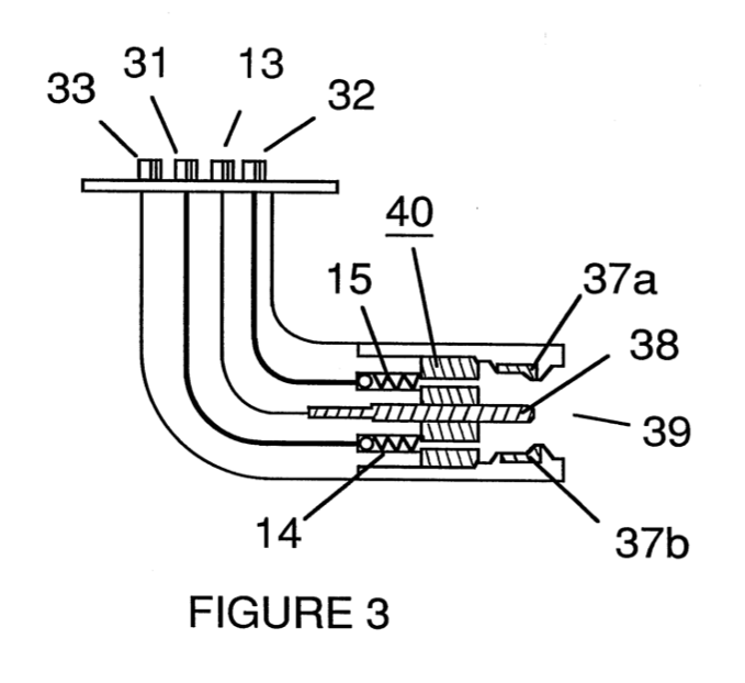 |
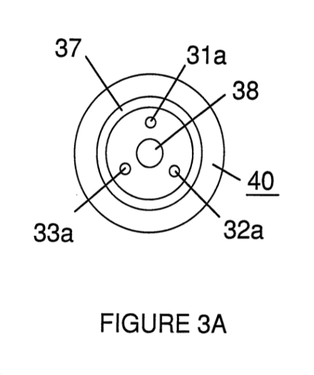
Figure 4 shows a disk array of injectors
Figure 5 shows the resonance electrical circuit including the injector.
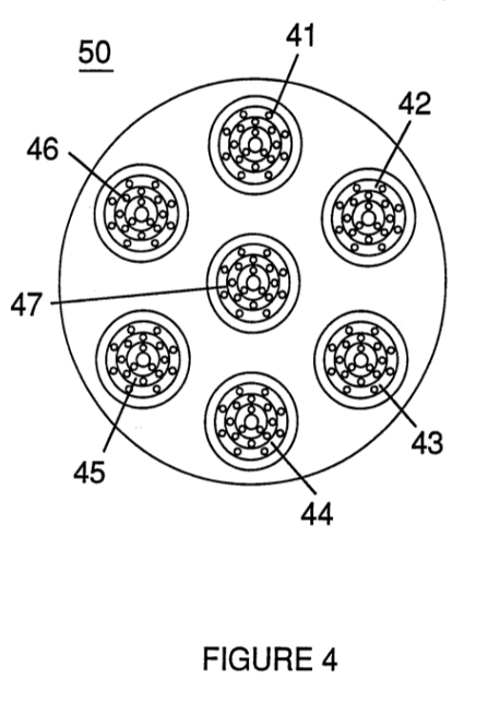 |
|
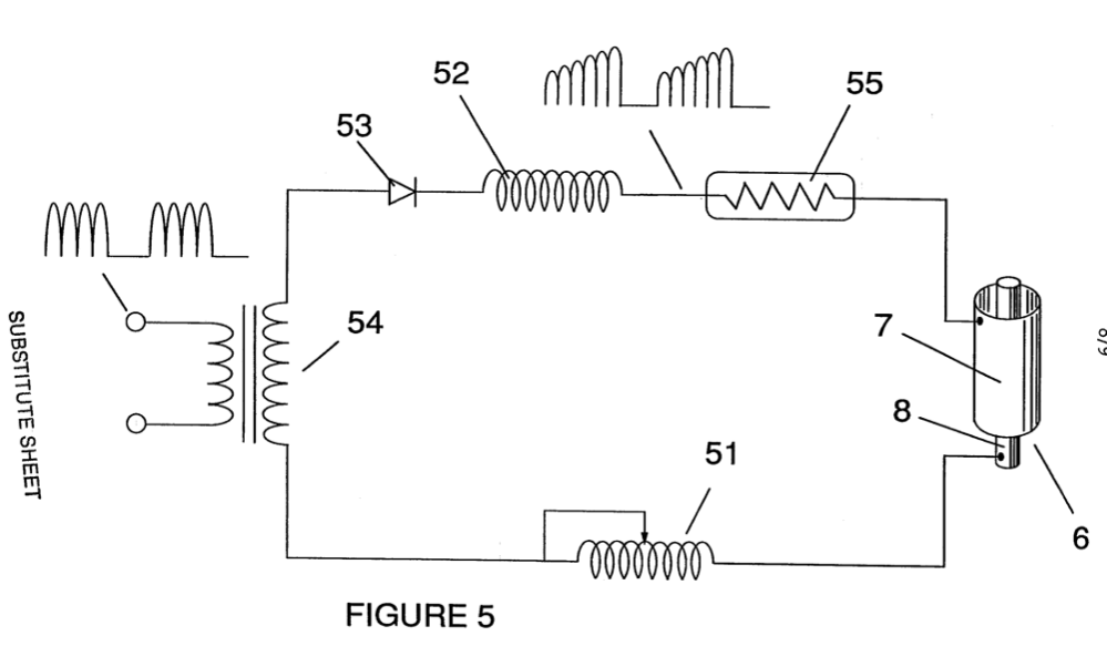
Figure 6 depicts the inter-relationship of the electrical and fuel distribution components of an injector system.
Although I refer to an “injector” herein, the invention relates not only to the physical configuration of an injector apparatus but also to the overall process. and system parameters determined in the apparatus to achieve the release of thermal energy. In a basic outline, an injector regulates the introduction into a combustion zone of process constituents and sets up a fuel mixture condition permitting combustion. That combustion condition is triggered Simultaneously with injector operation in real time correspondence with control parameters for the process constituents.
In the fuel mixture condition that is created by the injector, water (H20) is atomized into a fine Spray and mixed with (1) ionized ambient air gases and (2) other non-combustible gases such as nitrogen, argon and other rare gases, and water vapor. (Exhaust gas produced by the combustion of hydrogen with oxygen is a non-combustible water vapor. This water vapor and other inert gases resulting from combustion may be recycled from an exhaust outlet in the injector system back into the input mixture of non-combustible gases.) The fuel mix is introduced at a consistent flow rate maintained under a predetermined pressure. In the triggering of the condition created by the injector, the conversion process described in my patent no. 4,936,961 and co-pending application serial no. 07/460,859 is set off spontaneously on a “micro" level in a predetermined reaction zone. The injector creates a mixture, under pressure in a defined zone (or locus), of water, ionized gases and non-combustible gases. Pressure is an important factor in the maintenance of the reaction condition and causes the water mist/gas mixture to become intimately mixed, compressed, and destabilized to produce combustion when activated under resonance conditions of ignition. In accordance with the aforementioned conversion process of my patent and application, when water is subjected to a resonance condition water molecules expand and distend; electrons are ejected from the water molecule and absorbed by ionized gases; and the water molecule, thus destabilized, breaks down into its elemental components of hydrogen (2H) and oxygen (0) in the combustion zone. The hydrogen atoms released from the molecule provide the fuel source in the mixture for combustion with oxygen. The present invention is an application of that process and is outlined in Table I:
TABLE I
Injector Mixture + Process Conditions = Thermal Energy
(1) Water Mist (1) Release Under (1) Heat pressure into and Combustion Zone or and (2) Internal Combustion (2) Ionized Gas (2) Resonance utilizing Engine the dielectric (Explosive property of water force) : as a capacitor and or and (3) Jet Engine (3) Non-Combustible (3) Unipolar pulsing Gas at high voltage or (4) Other application
The process occurs as water mist and gases are injected under pressure into, and intimately mixed in the combustion zone and an electrically polarized zone. In the electrically polarized zone, the water mixture is subjected to a unipolar pulsed direct current voltage that is tuned to achieve resonance in accordance with the electrical, mass and other Characteristics of the mixture as a dielectric in the environment of the combustion zone. The resonant frequency will vary according to injector configuration and depends upon the physical characteristics, such as mass and volume of gases in the zone. As my prior patents and application point out, the resonant condition in the capacitive circuit is determined by the dielectric properties of water: (1) as the dielectric in a capacitor formed by adjacent conductive surfaces and (2) as the water molecule itself is a polar dielectric material. At resonance, current flow in the resonant electrical circuit will be minimized and voltage will peak.
The injector system provides a pressurized fuel mixture for subjection to the resonant environment of the voltage combustion zone as the mixture is introduced to the zone. In a preferred embodiment, the injector includes concentrically nested serial orifices, one for each of three constituent elements of the fuel mixture. (It may be feasible to combine and process non-combustible and ionized gases in advance of the injector. In this event only two orifices are required, one for the water and the other for the combined gases.) The orifices disperse the water mist and gases under pressure into a conically shaped activation and combustion zone (or locus).
Figure 1A shows a transverse cross-section of an injector in which supply lines for water 1 ionized gas 2 and non-combustible gas 3 feed into a distribution disk assembly 4 having concentrically nested orifices. The fuel mixture passes through a mixing zone 5 and voltage zone 6 created by electrodes or conductive surfaces 7a and 7b (positive) and 8 (negative or ground). Electrical field lines as shown as 6a1 and 6a2 and 6bl and 6b2. Combustion (i.e., the oxidation of hydrogen) occurs in the zone 9. Ignition of the hydrogen can be primed by a spark or may occur spontaneously as a result of the exceptionally high volatility of hydrogen and its presence in a high voltage field. Although a differentiation of the mixing zone, the voltage zone and the combustion zone is made in explaining the invention, that differentiation relates to events or conditions in a process continuum, and as is evident from Figure 1, the zones are not physically discrete. In the zone(s), there is produced an "excited" mixture of vaporized water mist, ionized gases and other non-combustible gases all of which have been instantaneously released from under high pressure. Simultaneously, the released mixture is exposed to a pulsed voltage in the zone/locus at a frequency corresponding to electrical resonance, Under these conditions, outer shell electrons of atoms in the water molecule are de-stabilized and molecular time share is interrupted. Thus, the gas mixture in the injector zone is subjected to physical, electrical and chemical interactive forces which cause a breakdown of the atomic bonding forces of the water molecule.
Process parameters are determined based on the size of a particular injector. In an injector sized appropriately for use to provide a fuel mixture to a conventional cylinder in a Passenger vehicle automobile engine, the injector may resemble a conventional spark plug. In such an injector, the water orifice is .10 to .15 inch in diameter; the ionized gas orifice is -15 to 20 inch in diameter; and the non-combustible gas orifice is .20 to .25 inch in diameter. In such a configuration, the serial orifices increase in size from the innermost orifice, as appropriate to a concentric configuration. As noted above, the introduction of the fuel components is desirably maintained at a constant rate; maintenance of a back pressure of about 125 pounds per square inch for each of the three fuel gas constituents appears satisfactorily useful for a “spark-plug" injector. In the pressurized environment of the injector, spring loaded one-way check valves in each supply line, such as 14 and 15, maintain pressure during pulse off times.
The voltage zone 6 surrounds the pressurized fuel mixture and provides an electrically charged environment of pulsed direct current in the range from about 500 to 20,000 and more volts at a frequency tuned into the resonant characteristic of the mixture. This frequency will typically lie within the range of from about 20KHz to about 50 KHz, dependent, as noted above, on the mass flow of the mixture from the injector and the dielectric property of the mixture. In a spark-plug sized injector, the voltage zone will typically extend longitudinally about .25 to 1.0 inch to permit sufficient dwell time of the water mist and gas mixture between the conductive sufaces 7 and 8 that form a capacitor so that resonance occurs at a high voltage pulsed frequency and combustion is triggered. In the zone, an energy wave is
In the voltage zone, the time share ratio of the hydrogen and oxygen atoms comprising the individual water molecules in the water mist is upset in accordance with the process explained in my aforementioned patent no. 4,936,961 and application serial no. 07/460,859. To wit, the water molecule which is itself a polar structure, is distended or distorted in shape by being subjected to the polar electric field in the voltage zone. The resonant condition induced in the molecule by the unipolar pulses upsets the molecular bonding of shell electrons such that the water molecule, at resonance, breaks apart into its constituent atoms. In the voltage zone, the water (H20) molecules are excited into an ionized state; and the pre-ionized gas component of the fuel mixture captures the electrons released from the water molecule. In this manner at the resonant condition, the water molecule is destabilized and the constituent atomic elements of the molecule, 2H and O, are released; and the released hydrogen atoms are available for combustion. The non-combustible gases in the fuel mixture reduce the burn rate of hydrogen to that of a hydrocarbon fuel such as gasoline or kerosene from its normal burn rate (which is approximately 2.5 times that of gasoline). Hence the presence of non-combustible gases in the fuel mixture moderates energy release and modulate the rate at which the free hydrogen and oxygen molecules combine in the combustion process.
The conversion process does not spontaneously occur and the condition in the zone must be carefully fine tuned to achieve an optimum input flow rate for water and the gases corresponding to the maintenance of a resonant condition. The input water mist and gases may likewise be injected into the zone in a physically pulsed [on/off] manner corresponding to the resonance achieved. In an internal combustion engine, the resonance of the electrical circuit and the physical pulsing of the input mixture may be required to he related to the combustion cycle of the reciprocating engine. In this regard, one or two conventional spark plugs may require a spark cycle tuned in correspondence to the conversion cycle resonance so that combustion of the mixture will occur. Thus, the input flow, conversion rate and combustion rate are interrelated and optimally should each be tuned in accordance with the circuit resonance at which conversion occurs.
The injection system of the present invention is suited to retrofit applications in conventionally fueled gasoline and diesel internal combustion engines and conventionally fueled jet aircraft engines.
EXAMPLE 1
Figures 2A, 2B and 2C illustrate a type of injector useful, inter alia as a fuel source for a conventional internal combustion engine, In the cross-section of Figure 2A, reference numerals corresponding to identifying numerals used in Figure 1 show a supply line for water 1 leading to first distribution disc la and supply line for ionized gas 2, leading to second distribution disc 2a. In the cross section, the supply line for non-combustible gas 3 leading to distribution disc 3a is not illustrated, however, its location as a third line should be self-evident. The three discs comprise distribution disc assembly 4. The supply lines are formed in an electrically insulating body 10 surrounded by electrically conductive sheath/housing 11 having a threaded end segment 12.
A central electrode 8 extends the length of the injector. Conductive elements 7a and 7b (7a and 7b depict oppositive sides of the diameter in the cross-section of a circular body) adjacent threaded section 12 form, with electrode 8, the electrical polarization zone 6 proximate to combustion zone 9. An electrical connector 13 may be provided at the other end of the injector. (As used herein “electrode" refers to the conductive surface of an element forming one side of a capacitor.) In the frontal view of Figure 2B it is seen that each disc comprising the distribution disc assembly 9, includes a plurality of micro-nozzles lal, 2al, 3al, etc., for the outlet of the water and gases into the polarization/voltage and combustion zones. The exploded view of Figure 2C shows another view of the injector and additionally depicts two supply line inlets 16 and 17, the third not being shown (because of the inability to represent the uniform 120° separation of three lines in a two-dimensional drawing).
In the injector, water mist (forming droplets in the range, for example, of from 10 to 250 microns and above, with size being related to voltage intensity) is injected into fuel-mixing and polarizing zone by way of water spray nozzles lal. The tendency of water to form a “bead" or droplet is a parameter related to droplet mist Size and voltage intensity. Ionized air gases and non-combustible gases, introduced through nozzles 2al and 3al, are intermixed with the expelling water mist to form a fuel-mixture which enters into voltage zone 6 where the mixture is exposed to a pulsating, unipolar high intensity voltage field (typically 20,000 volts at 50 Khz or above at the resonant condition in which current flow in the circuit (amps) is reduced to a minimum) created between electrodes 7 and 8.
Laser energy prevents discharge of the ionized gases and provides additional energy input into the molecular destabilization process that occurs at resonance. It is preferable that the ionized gases be subjected to laser (photonic energy) activation in advance of the introduction of the gases into the zone(s); although, for example, a fiber optic conduit may be useful to direct photonic energy directly into the zone. Heat generated in the zone, however, may affect the operability of such an alternative configuration. The electrical polarization of the water molecule and a resonant condition occurs to destabilize the molecular bonding of the hydrogen and oxygen atoms. By spark ignition, combustion energy is released.
To ensure proper flame projection and subsequent flame stability, pumps for the ambient air, non-combustible gas and water introduce these components to the injector under Static-pressure up to and beyond 125 psi.
Flame temperature is regulated by controlling the volume flow-rate of each fluid-media in direct relationship to applied voltage intensity. To elevate flame temperature, fluid displacement is increased while the volume flow rate of non-combustible gases is maintained or reduced and the applied voltage amplitude is increased. To lower flame temperature, the fluid flow rate of non-combustible gases is increased and pulse voltage amplitude is lowered. To establish a predetermined flame temperature, the Fluid media and applied voltage are adjusted independently. The flame-pattern is further maintained as the ignited, compressed, and moving gases are projected from the nozzle-ports in distribution disc assembly 4 under pressure and the gas expands in the zone and is ignited.
In the voltage zone several functions occur simultaneously to initiate and trigger thermal energy-yield. Water mist droplets are exposed to high intensity pulsating voltage fields in accordance with an electrical polarization process that separates the atoms of the water molecule and causes the atoms to experience electron ejection. The polar nature of the water molecule which facilitates the formation of minute droplets in the mist appears to cause a relationship between the droplet size and the voltage required to effect the process, i.e. the greater the droplet size, the higher the voltage required. The liberated atoms of the water molecule interact with laser primed ionized ambient air gases to cause a highly energized and destabilized mass of combustible gas atoms to thermally ignite. Incoming ambient air gases are laser primed and ionized when passing through a gas processor; and an electron extraction circuit (Figure 5) captures and consumes in sink 55 ejected electrons and prevents electron flow into the resonant circuit.
In terms of performance, reliability and safety, ionized air gases and water fuel liquid do not become volatile until the fuel mixture reaches the voltage and combustion zones. Injected non-combustible gases retard and control the combustion rate of hydrogen during gas ignition.
In alternate applications, laser primed ionized liquid oxygen and laser primed liquid hydrogen stored in separate fuel-tanks can be used in place of the fuel mixture, or liquefied ambient air gases alone with water can be substituted as a fuel-source.
The injector assembly is design variable and is retrofit-able to fossil fuel injector ports conventionally used in jet/rocket engines, grain dryers, blast furnaces, heating systems, internal combustion engines and the like.
EXAMPLE II
A flange mounted injector is shown in cross-section in Figure 3 which shows the fuel mixture inlets and illustrates an alternative three (3) nozzle configuration leading to the polarization (voltage) and combustion zones in which one nozzle 3la, 32a and 33a for each of the three gas mixtures is provided, connected to supply lines 31 and 32 (33. not shown). Electrical polarization zone 36 is formed between electrode 38 and surrounding conductive shell 37. The capacitative element of the resonant circuit is formed when the fuel mixture, as a- dielectric, is introduced between the conductive surfaces of 37 and 38. Figure 3A is a frontal view of the operative end of the injector.
EXAMPLE III
Multiple injectors may be arranged in a gang as shown in Figure 4 in which injectors 40, 41, 42, 43, 44, 45, 46, 47, 48 and 49 are arranged concentrically in an assembly 50. Such a ganged array is useful in applications having intensive energy requirements such as jet aircraft engines, and blast furnaces.
EXAMPLE IV
The basic electrical system utilized in the invention is depicted in Figure 5 showing the electrical polarization zone 6 which receives and processes the water and gas mixture as a Capacitive circuit element in a resonant charging circuit formed by inductors 51 and 52 connected in series with diode 53, pulsed voltage source 54, electron sink 55 and the zone/locus 6 formed from conductive elements 7 and 8. In this Manner, electrodes 7 and 8 in the injector form a Capacitor which has electrical characteristics dependent on the dielectric media (e.q., the water mist, ionized gases, and non-combustible gases) introduced between the conductive elements. Within the macro-dielectric media, however, the water molecules themselves, because of their polar nature, can be considered micro-capacitors.
EXAMPLE V
Fuel distribution and management systems useful with the injector of this application are described in my co-pending applications for patent, PCT/US90/6513 and PCT/US90/6407
A distribution block for the assembly is shown in Figure 6. In Figure 6 the distribution block pulses and synchronizes the input of the fuel components in sequence with the electrical pulsing circuit. The fuel components are injected into the injector ports in synchronization with the resonant frequency to enhance the energy wave pulse extending from the voltage zone through the flame. In the configuration of Figure 6, the electrical system is interrelated to distribution block 60, gate valve 61 and separate passageways 62, 63, and 64 for fuel components. The distributor produces a trigger pulse which activates a pulse shaping circuit that forms a pulse having a width and amplitude determined by resonance of the mixture and establishes a dwell time for the mixture in the zone to produce combustion.
As in my referenced application regarding control and management and distribution systems for a hydrogen containing fuel gas produced from water, the production of hydrogen gas is related to pulse frequency on/off time. In the system shown in Figure 6, the distributor block pulses the fluid media introduced to the injector in relationship to the resonant pulse frequency of the circuit and to the operational on/off gate pulse frequency. In this manner the rate of water conversion (i.e., the rate of § fuel production by the injector) can be regulated and the pattern of resonance in the flame controlled.
What is claimed is:
1. The improved method of converting water into a hydrogen containing fuel comprising:
providing a mist of water in a defined zone determined by conductive members, the surfaces of which define the opposite plates of a capacitive element in a resonant circuit, and
subjecting the water mist in the zone to a unipolar pulsing electrical signal, such that resonance of the circuit is achieved, whereby hydrogen is disassociated from water molecules in the zone as a gas.
2. The method of claim 1 in which the resonant Circuit is an electrical circuit including an inductive member.
3. The method of Claim 2 in which the inductive member is in series relationship with the capacitive element.
A. The method of Claim 1 in which non-combustible gases are injected with water into the zone.
5. The method of Claim 1 in which ionized gases are injected with water into the zone. WO 92/22679 . PCT/US91/03476
6. The method of Claim 5 in which the ionized gases are subjected to excitation by photons.
7. ‘The method of Claim 1 or Claim 2 or Claim 3 or Claim 4 or Claim 5 or Claim 6 including the oxidation of the hydrogen gas released to produce thermal energy.
8. The method of Claim 1 or Claim 2 or Claim 3 or Claim 4 or Claim 5 or Claim 6 including the oxidation of the hydrogen gas released to produce an explosive force of combustion.
9. The method of Claim 1 or Claim 2 or Claim 3 or Claim 4 or Claim 5 or Claim 6 in which the media in the zone is subjected in the zone to physical pulsing corresponding to the resonance of the circuit.
10. Apparatus useful in a method for the conversion of water into a hydrogen fuel including:
electrically conductive surfaces that form the opposite surfaces of an electrically capacitive element in a circuit;
means for injecting water as a fine mist into the zone defined by the electrically conductive surfaces; and
means for achieving resonance in the circuit at a frequency determined substantially by the dielectric properties of the water in the zone, whereby hydrogen is disassociated from water molecules in the zone as a gas.
11. Apparatus in accordance with Claim 10 including means for the injection of gases with water into the zone to produce a mixture and in which the resonant frequency is related to the dielectric properties of the mixture.
12. Apparatus in accordance with Claim 10 or Claim Ill including means for causing ignition of the hydrogen gas.
13. Apparatus in accordance with Claim 10 or Claim 11 including further means for subjecting the media in the zone to physical pulsing.
SUBSTITUTE SHEET ‘INTERNATIONAL SEARCH REPORT _
International Application No, PCT /US91/03476 |. CLASSIFICATION OF SUBJECT MATTER (:f several classification symbols aoply, indinate all) ¢ According to Intarnatranal Patent Classification ech a 9 beth National Classification and 1PC i} at 87700
TPC(5): C25B 1/02, FOZB 00, FO U.S. CL.: 204/129 123/536, 25B
i. FIELOS SEARCHED
Minimum Documentation Searened 7
Classification System « Classification Symnois
U.S. 204/129 123/536, 25B
Documentation Searched other than Minimum Documentation to the Extent that such Documents are Included in the Fields Searched @
ll. DOCUMENTS CONSIDERED TO BE RELEVANT ®
Category * Citation of Qocument, || with indication, where appropriate, of the relevant passages 12 Relevant to Claim No. 3 x US, A, 4,185,593 (McCLURE) 29 January 1980, 1,2,7,8,
See entire document. 10,12,13 X US, A, 5,010,869 (LEE) 30 April 1991, 10-13
See entire document.
XY US, A, 3,648,668 (PACHECO) 14 March 1972, 1-13 See entire document. ,
Y US, A, 3,946,711 (WIGAL) 30 March 1976, 1-13 See entire document.
Y US, A, 4,023,545 (MOSHER ET. AL.) 17 May 1977, 1-13 See Abstract.
¥ US, A, 4,052,139 (PATLLAUD ET. AL.) 04 October 1977,1-13 See figure and document.
Y US, A, 4,613,304 (MEYER) 23 September 1986, 1-13 See entire document.
“T" later document published after the international filing date
* Special categories of cited documents: ' Gecument published after the international filg date “aH i or priority cate an ot in contlict wil ui A decumant defining the general state of the art whieh 1s not cited to understand the principle or theory underlying the invention "“€" earlier document but published on or after the international "%" document of particular relevance; the claimed invention filing date cannot be considered novel or cannot be considered to "CL" document which may throw oubts on priority claum(a) or involve an inventive step which is cited to astablish-the publication date of another = aye document of particular relevance; the claimed invention citation or ather special reason (a8 specified) cannot be considered to invaive an inventive step when the document is combined with ane ar more other such documents, such combination being obvious to a person skilled in the a “&" document member of the same patent family 4O" document referring to an oral disclosure, use, exhibition or other means
“P" document published prior to the internatianal filing date but later than the priority date claimed
IV. CERTIFICATION
Date of the Actual Completion of the International Search : Date of Mailing of this International Search Report
21 NOY 1991
31 OCTOBER 1991
FURTHER INFORMATION CONTINUEO FROM THE SECOND SHEET
XY US, A, 4,797,186 (LEVY ET. AL.) 10 JANUARY 1999, 1-9 See entire document.
Y US, A, 4,826,581 (MEYER) 02 May 1989, 1-13 See entire document.
Y | US, A, 4,936,961 (MEYER) 26 June 1990, 1-13 See entire document.
OBSERVATIONS WHERE CERTAIN CLAIMS WERE FOUND UNSEARCHAGLE '
This international search report has not been established in resnect of certain claims under Articte 17(2) (a) for the fallawing reasons:
0 Claim numbers because they relate to subject matter = not required ta be searched by this Authority, namely:
20] Claim numbers ___ . because they relate to parts of the international application that do not comply with the prescribed raquira- ments to such an extent that na meaningful international search can be carried out !5, specifically:
30 Claim numbers___, because they are dependent claims nor drafted in. accordance wiih the second and third sentences of PCT Rule 6.4{a).
OBSERVATIONS WHERE UNITY OF INVENTION IS LACKING?
This International Searching Authority found multiple inventions in this international! application as fallows:
1] As ail required additional search fees were timely paid by the applicant, this international search report covers all searchable claims of the international application.
20] At only some of the required additional search fees were timely paid by the applicant, this international search report covers only those claims of the international application for which fees were paid, specifically claims:
30 No required additional search fees were timely paid by the applicant. Consequently, this international search report Is restricted to the invention first mentioned In the claims; it ls covered by claim numbers:
4 As all searchable claims could be searched without effort justifying an additional fee, the international Searching Authority did not invite payment of any additional fee. .
Remark on Protest Co The additional search fees were accompanied by applicant's protest. No protest accompanied the payment of additional search fees.
|
|
|
WO8901464A3 - Controlled Process for the Production of Thermal Energy from Gases and Apparatus Useful Therefor
PDF Download: SMeyer-WO8901464A3-Controlled_Process_for_the_Production_of_Thermal_Energy_from_Gases_and_Apparatus_Useful_Therefor.pdf
WORLD INTELLECTUAL PROPERTY ORGANIZATION International Bureau
INTERNATIONAL APPLICATION PUBLISHED UNDER THE PATENT COOPERATION TREATY (PCT)
(S1) International Patent Classification 4 : HO5H 15/00 A3
(11) International Publication Number: WO 89/ 01464
(43) International Publication Date: 23 February 1989 (23.02.89)
(22) International Filing Date: 4 August 1988 (04.08.88) | (31) Priority Application Number: 081,859 (82) Priority Date: 5 August 1987 (05.08.87) (33) Priority Country: US
(71}(72) Applicant and Inventor: MEYER, Stanley, A. [US/
(74) Agent: BARANOWSKI, Edwin, M.; Porter, Wright,
(21) International Application Number: — PCT/US88/02680
US]; 3792 Broadway, Grove City, OH 43123 (US).
Morris & Arthur, 41 S. High Street, Columbus, OH 43215 (US).
(8t)-Designated States: AT (European patent), BE (Euro- pean patent), CH (European patent), DE (European patent), FR (European patent), GB (European pa- tent), IT (European patent), JP, LU (European pa- tent), NL (European patent), SE (European patent).
Published With international search report. . Before the expiration of the time limit for ‘amending the claims and to be republished in the event of the receipt of amendments,
(88) Date of publication of the international search report: ~ 9 March 1989 (09.03.89)
APPARATUS USEFUL THEREFOR
(&7) Abstract
A method of and apparatus for obtaining the release of energy from a gas mixture including hydrogen and oxygen in which charged ions are stimulated to an activated state, and then passed through a resonant cavity, where successively increasing energy levels are achieved, and finally passed to an outlet orifice to produce thermal explosive energy.
(54)Title: CONTROLLED PROCESS FOR THE PRODUCTION OF THERMAL ENERGY FROM GASES AND
ii. DOCUMENTS CONSIDERED TO BE RELEVANT 9
Category * Citation of Document, 1 with indication, where appropriate, of the relevant passages 12 Relevant to Claim. No. 13 x US,A, 4,233,109 (NISHIZAWA) 2 11 November 1980, See figure 7 and entire specification. A US,A, 4,406,765 (HIGASHI ET AL) 27 September 1983, See abstract and figure 7. A,P | US,A, 4,687,753 (FIATO ET AL) 18 August 1987, See abstract and figure 1. AP US,A, 4,695,357 (BOUSSERT) fiqure 1. :
22 September 1987, See abstract and
IV. CERTIFICATION
Date of the Actual Completion of the International Search 29 January 1989
International Searching Authority IsA/US
Date of Mailing of this International Search Report
O8FEB 1989
Signature of Authorized Offcer ~ ~ : , 7 - Ae (hls
Stephen J. Kalafut
Form PCTASA/210 (second sheet) (Rev.11-87)
WO9208046A1 - Hydrogen Gas Fuel & Management System For An Internal Combustion Engine
PDF Download: SMeyer-WO9208046A1-Hydrogen_Gas_Fuel_&_Management_System_For_An_Internal_Combustion_Engine.txt
WORLD INTELLECTUAL PROPERTY ORGANIZATION International Bureau
INTERNATIONAL APPLICATION PUBLISHED UNDER THE PATENT COOPERATION TREATY (PCT)
(51) International Patent Classification 5; F02M 21/02, 25/07, 27/00 Al
(43) International Publication Date:
(11) International Publication Number: WO 92/08046 14 May 1992 (14.05.92)
(21) International Application Number: PCT/US90/06513
(22) International Filing Date: 2 November 1990 (02.11.90)
(71)(72) Applicant and Inventor: MEYER, Stanley, A. [US/US]; 3792 Broadway, Grove City, OH 43123 (US).
(74) Agent: BARANOWSKI, Edwin, M.; Porter, Wright, Mor- tis & Arthur, 41 South High Street, Columbus, OH 43215 (US).
(81) Designated States: AT (European patent), AU, BE (Euro- pean patent), CA, CH (European patent), DE (European patent), DK (European patent), ES, ES (European pa- tent), FR (European patent), GB (European patent), GR (European patent), IT (European patent), JP, KR, LU (European patent), NL (European patent), SE (European patent), US.Published With international search report.
(54) Title: HYDROGEN GAS FUEL AND MANAGEMENT SYSTEM FOR AN INTERNAL COMBUSTION ENGINE UTILIZING HYDROGEN GAS FUEL
Abstract
A gas fuel for an internal combustion engine (1, 2) comprising a mixture of gases having a proportion of hydrogen to oxygen of approximately 2:1 and a regulated density of the hydrogen component of the mixture such that the burn rate of the mixture approximates that of a fossil fuel and a system (11) for characteristics in an internal combustion engine (1, 2).
HYDROGEN GAS FUEL AND MANAGEMENT SYSTEM FOR AN INTERNAL COMBUSTION ENGINE UTILIZING HYDROGEN GAS FUEL
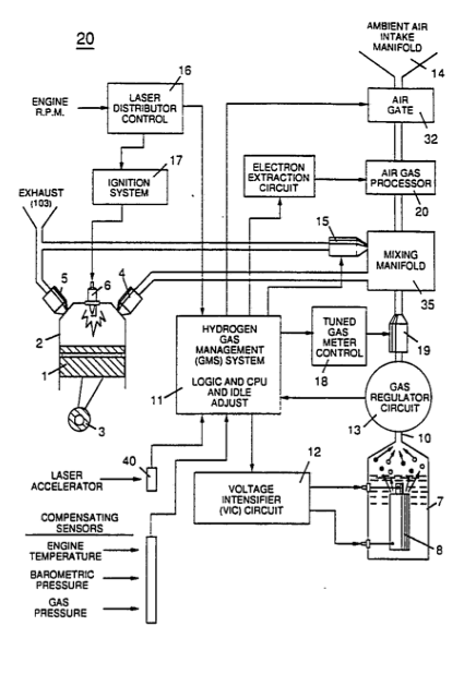 Hydrogen has long been regarded as an efficient, abundant and potentially non-polluting energy source. Yet despite such desirable attributes, hydrogen has not been “widely, Or practically, applied in applications where the use of hydrogen as a fuel is self-evidently desirable, such as in motor vehicles powered by internal combustion engines.
In part, practical use of hydrogen is inhibited by difficulties in the safe transmission of the gas. Hydrogen has an inherent high volatility and a correspondingly rapid dispersion characteristic in other gas mixtures such as the atmosphere, Further, it is difficult to control the distribution of a hydrogen gas fuel and to maintain consistent combustion characteristics for a hydrogen gas fuel, particularly in a motor vehicle internal combustion engine.
It is an object of this invention to overcome such difficulties and to provide a fuel gas management and delivery system for internal combustion engines that utilize hydrogen as a fuel, The system includes a safe and effective distribution means for supplying a hydrogen fuel to an internal combustion engine, means for fuel injection applications of hydrogen fuel in such an engine, means for controlling the burn rate of hydrogen for the efficient use of a hydrogen fuel gas, and means for overcoming prior art problems of engine shut down caused by an over-enrichment of hydrogen in the fuel supply to the engine.
In particular, when hydrogen gas fuel is used in a motor vehicle internal combustion engine, an over-enrichment of the hydrogen component of the fuel gas injected into the engine frequently occurs and results either in (1) an engine shut down, because of the narrow combustion window (a term defined hereinafter) for hydrogen, or (2) a significant waste of the “over-enriched" portion of the fuel not combusted--the fuel is expelled in the engine exhaust. In prior art attempts, mechanical meters, valves and switches that were conventionally used in engine fuel systems for petroleum based, fossil fuels were too Slow to adapt to engine conditions. Similarly, prior art system included processors that were intended to control the engine in view of predetermined operating parameters with little regard for engine effects caused by the injection of a hydrogen fuel.
As a result over-enrichment of hydrogen in the fuel/combustion mixture consistently remains a problem in the development of a hydrogen fueled internal combustion engine. Conventional hydrogen fueled engines are prone to shut down and do not Smoothly operate over the extended range of engine speeds considered desirable and necessary in a motor vehicle.
It is accordingly an object of this invention to provide a £uel distribution system for a hydrogen fueled internal combustion engine that reduces the problem of fuel over-enrichment and provides a smooth operating characteristic for engine speeds required in conventional use.
It is also an object to provide a "tuned" combustion system, adaptable not only for hydrogen, but also to other fuel stocks by which optimum combustion characteristics are Maintained for the fuel over the operating range of the engine,
And it is a further object to provide an integrated operating system including fuel generation and control means for a hydrogen fueled internal combustion engine.
These and other objects of the invention will become evident to those of skill in the art when the following description of the preferred embodiment is considered in conjunction with the drawings in which:
Figure 1 shows the combustion envelope of hydrogen compared to the combustion envelope of gasoline and illustrates a goal achieved by the invention in maintaining an optimum and uniform combustion rate for hydrogen throughout the effective range of engine RPM. As used herein, the "combustion envelope" refers to the range within which combustion of a fuel gas is possible, given a predetermined quantity of combustible fuel and its ratio to the combustion media, i.e. oxygen.)
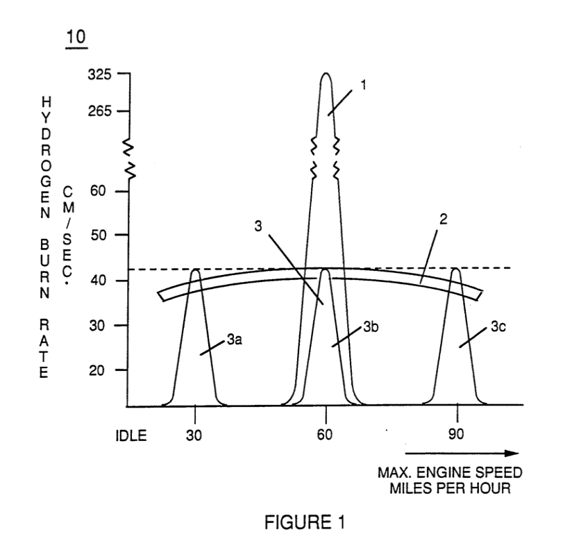
Figure 2 is a block diagram of a combustion management system for a hydrogen containing fuel gas mixture that is injected into a combustion chamber, showing the interrelationship of system Management controls with various engine parameters.
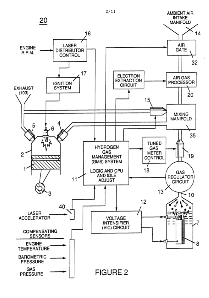
Figure 3 illustrates the physical arrangement of a hydrogen fuel gas control means and injection system for the regulation of fuel gas transmitted to an engine combustion chamber.

Figure 4 shows an air gas processor useful in the system of the invention in a cross-sectional side view; Figure 4A shows a top plan view; and Figure 4B is a bottom view.
|
|
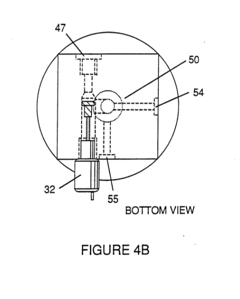 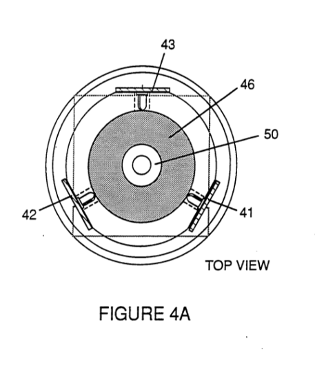 |
Figure 5 shows a “quenching conduit" for the safe distribution of a hydrogen fuel in the engine environment, and Figures 5A and 5B shows alternative cross section configurations for said conduit.
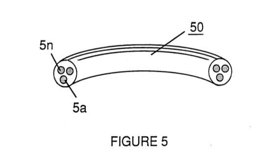
|
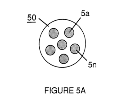
|
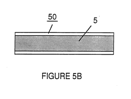 |
Figure 6 figuratively represents the modulating effect upon hydrogen gas characteristics of other non-combustible gases included in a fuel gas mixture containing hydrogen in accord with the invention and its fuel gas management system.
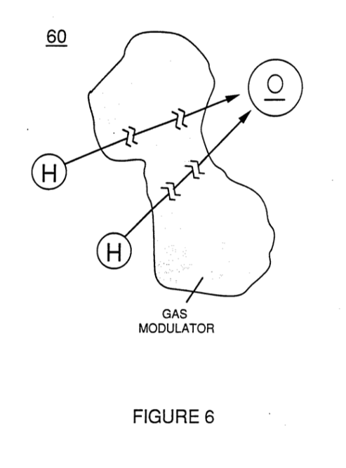
Figure 7 shows the electron extractor circuit used in the air processor section to ionize and maintain the ionization of introduced air gas.
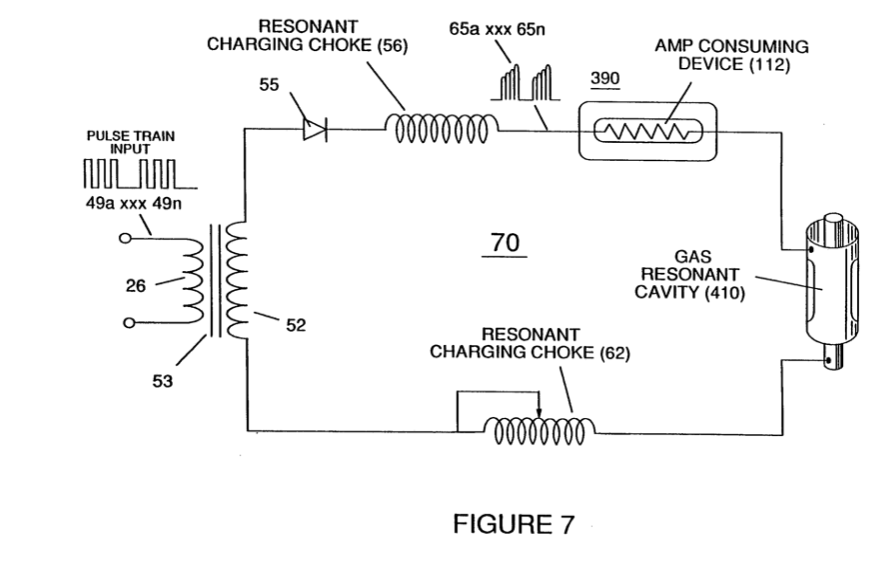
In my prior United States Letters Patents, I have, inter alia, described means for the production of a fuel gas mixture having a hydrogen component, United States Letters Patent No. 4,936,961; means for the enhancement of the energy output of a fuel gas, United States Letters Patent No. 4,826,581; and an electrical circuit control system for a hydrogen fuel gas generator, United States Letters Patent No. 4,798,661.
In my present application, I describe an integrated fuel gas management system that enables hydrogen to be efficiently, reliably and safely used as a fuel gas in an internal combustion engine having a configuration derived from conventional engines fueled by a fossil fuel, such as gasoline, diesel or other petroleum or hydrocarbon derivative.
In the prior art, Significant effort directed towards the utilization of hydrogen as a vehicle fuel has attempted to devise a hydrogen powered internal combustion engine that emulates the characteristics of a conventional hydrocarbon fueled (gasoline, diesel, propane, methanol, etc.) engine System.
While such an extension of an existing technology to a hydrogen fuel appears logically proper, such prior art techniques have not fully considered:
(1) that the . volatility, or "burn rate", of hydrogen is many times greater than that of a fossil fuel, and
(2) that the combustion “window” for hydrogen in an oxygen containing atmosphere is exceedingly narrow, and is considerably narrower than that of a fossil fuel. A fuel such as gasoline or diesel oil will satisfactorily perform and Support combustion over a wide range of fuel mixtures having different proportional quantities of oxygen. Hydrocarbon fuels typically support engine speeds over a wide range in an internal combustion engine because of its broad combustion envelope; hydrogen in contrast, will combust Satisfactorily only when a hydrogen/oxygen mixture in the ratio of 2:1 is present. This factor makes combustion cycle development for hydrogen fuel a critical art in which the hydrogen burn rate (equated to power output of the engine) and the combustion mixture containing the hydrogen fuel must be carefully regulated over the entire RPM operating range - of an engine so that combustion is efficiently supported over the range.
The invention herein provides a gas fuel for an internal combustion engine comprising a mixture of gases including hydrogen, oxygen, and other gases that are not combustible with hydrogen in which the mixture includes a proportion of hydrogen to oxygen of approximately 2:1 and a predetermined density of hydrogen within the mixture gases such that the burn rate of the mixture approximates that of a fossil fuel. There is further management system provided for a fuel gas mixture containing hydrogen that is introduced as a fuel to an internal combustion engine that consists of means and process for monitoring the composition of a fuel gas mixture introduced into the engine such that the proportion of hydrogen to oxygen in the mixture is approximately 2:1; and means and process for modulating the density of the hydrogen component of the introduced fuel gas mixture by the addition of other non-combustible gases to the mixture such that the burn rate of the fuel gas mixture approximates that of a fossil fuel.
In the management system, apparatus for the distribution of the fuel gas mixture containing a hydrogen gas component is utilized which is formed from a plurality of conduits having an internal diameter of .015 to .025 inch intrinsically formed in an otherwise solid member.
In addition, the system includes a means and process for the mixing of a proportion of the exhaust gas of the engine into the fuel gas mixture introduced into the engine to provide modulation for the hydrogen in the fuel mixture. Thus, in a further aspect the invention is an improvement to a hydrogen fueled internal combustion engine that includes means and process for modulating the density of the hydrogen component of a fuel gas mixture introduced into the engine such that the burn rate of the fuel gas mixture containing hydrogen is reduced to the approximate burn rate of a fossil fuel. This means and process includes mixing a hydrogen containing fuel gas with at least one of ambient air and exhaust gas from the engine. These features of the invention are explained herein with reference to the figures.
With reference to Figure 1, it is an object of the invention to regulate a hydrogen fuel gas mixture that is introduced into the engine combustion chamber such that the burn rate of the hydrogen fuel gas remains constant regardless of engine RPM. As used herein, "burn rate" is an arbitrary measure of the relative volatility of a fuel gas (in contrast with the rate at which a given fuel is consumed, e.g., miles per gallon). Thus, it is an object to regulate the combustion "window" of hydrogen in a gas mixture so that optimum combustion is achieved, regardless of engine speed.
With reference to Table I, the extreme volatility of hydrogen in the atmosphere (burn rate: 325-265 cm/sec) is shown in contrast with the relatively equivalent burn rates of several known hydrocarbon and fossil fuels
(burn rates: 45-35 cm/sec):
TABLE I - Relative Burn Rates of Various Fuels
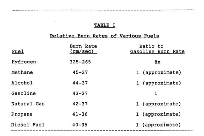
Image Text: Burn Rate Ratio to Fuel (cm/sec) Gasoline Burn Rate Hydrogen 325-265 8x Methane 45-37 1 (approximate) Alcohol 44-37 1 (approximate) Gasoline 43-37 1 Natural Gas 42-37 1 (approximate) Propane 41-36 1 (approximate) Diesel Fuel 40-35 l (approximate)
The combustion characteristics and high volatility of hydrogen can be charted with reference to an axis correlated to the running speed of an internal combustion engine, as illustrated by the narrow combustion envelope for hydrogen, shown in Figure 1 at 1 in contrast with the combustion envelope, for example, in gasoline, 2.
Typically, in the tuning of an engine for either optimum performance or efficiency, the low volatility and the wide combustion envelope of a fossil fuel permits an engine to be tuned, for example, to an optimum speed corresponding to 60 MPH, without concern for significant adverse effects or need for adjustment over the remaining engine operating range.
The narrow combustion envelope of hydrogen, however, prevents such broad tuning and consequently results in fuel over-enrichment and the engine operation difficulties noted above, passim.
In the invention, the burn rate of the hydrogen fuel gas is adjusted to be equivalent to that of a fossil fuel by the introduction into the hydrogen fuel of other non-combustible gases that serve as a modulator of the inherent volatility of the hydrogen. In addition, the hydrogen/oxygen ratio of 2:1 which represents the optimum combustion ratio for a hydrogen fuel is uniformly maintained in the modulated fuel mixture over the engine operating range, e.g. at speeds represented by 3a, 3b, 3c. The combustion window of hydrogen at a modulated given volatility remains in the same 2:1 hydrogen:oxygen ratio. Thus, the modulated burn rate of the hydrogen fuel gas, adjusted downward to 43-37 cm/sec, is maintained uniformly in the range of speeds from idling to maximum RPM, in contrast with conventional engine design based on typical gasoline burn rate, which is not usually adjusted. Nevertheless, because of the wide combustion window for gasoline, optimum tuning at 60 MPH as shown at 2 in Figure 1 will allow Satisfactory engine operation to other speeds. In the prior art, use of un-modulated hydrogen allowed engine operation only in the narrow envelope figuratively shown in curve 1.
In the invention, a processed gas mixture including a hydrogen fuel component having a uniform, predetermined volatility is generated by the system and introduced into the engine in a proper mixture to insure optimum combustion throughout the range of engine operating speeds.
Figure 2 shows a block diagram of a complete hydrogen gas management system. For explanation and illustration purposes, one cylinder of an engine is shown, however, it is appreciated that adaptations of the system to multiple cylinder engines are within the skill of the art.
In the system diagram of Figure 2, there is shown a conventional reciprocating piston internal combustion engine configuration including piston 1 and cylinder 2 connected to a rod and crankshaft mechanism 3, fuel intake valve 4, exhaust valve 5, and spark plug 6. Valves 4 and 5 and spark plug 6 are operatively interconnected to the management system of the invention.
One aspect of an overall system provides a source of fuel gas including hydrogen, such as a water fuel cell, 7, described in my United States Letter Patent No. 4,936,961 including water capacitor 8 immersed in a volume of water 9 which produces a source of a hydrogen/oxygen and non-combustible gas mixture 10 that is operatively interconnected with the gas management system 11 through regulator 13. Preferably the gas management system 11 includes a logic module and central processing unit interconnected to sensors and controllers in the.system.
The voltage intensifier circuit 12 regulates voltage amplitude, pulse frequency and gated pulse frequency associated with operation of the fuel cell 7. (See U.S. Letters Patent 4,936,961, Figure 1, and U.S. Letters Patent 4,798,661.) and is operatively interconnected to the gas management module.
The gas pressure regulator 13 is included proximate the exit orifice of the cell to maintain a consistent back pressure (optimally 15 psi in the preferred embodiment) in the fuel delivery system.
The gas management system logic module 1l determines the mixing of the hydrogen fuel gas mixture 10 produced by the cell with other modulating gases such as ambient air, introduced through manifold 14 and/or exhaust gas introduced through gate 15: The management system module includes inputs from sensors relating to air and engine temperature, engine RPM, gas pressure and the vehicle accelerator or engine speed control 40 which determines the speed at which the engine operates.
A distributor control 16, as in a conventional internal combustion engine, determines ignition system function 17 and additionally provides an input signal for a tuned gas meter control 18 that is operatively interconnected to the injector port 19 so that a uniform quantity of modulated fuel gas is injected through valve 4 into the cylinder upon each operating cycle of the cylinder, Air gas processor 20 is also included for treatment of gas derived from ambient air introduced in the system through the intake manifold.
(See Figures 3, 4, 4A, 4B and discussion, infra.)
|
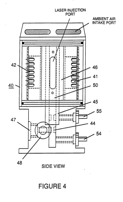 |
 |
|
Figure 3 illustrates an appropriate mechanical configuration adapted to the overall system shown in Figure 2. An intake manifold (not shown) directs ambient air 101 to air filter assembly 31 operatively interconnected to an inlet vaive 32 which is regulated by the management module and controls the flow of air into air processor 33 which produces a source of ionized non-combustible gases 102, that in turn may be mixed with non-combustible cylinder/engine exhaust gases 103 introduced at exhaust gate 15. These gases are mixed in the intake manifold 35 with gas from the fuel cell 7, introduced at injector port 19 whereupon the modulated combustion mixture having the hydrogen fuel component in the correct proportion with oxygen is delivered to the cylinder at a burn rate equivalent to that of a fossil or hydrocarbon fuel. An oil inlet port 110 for lubrication is optional. Thus, in the air processor ambient air 101 is ionized and the ionized gas 102, and other modulating gas such as the exhaust gas 103 is mixed until the fuel gas 10 for introduction to the cylinder at the modulated burn rate. Lubricating oil mist is shown at 111.
Appropriate sensors for monitoring air pressure, RPM and engine temperature are operatively interconnected with the management module and controllers regulate various fuel source or fuel gas mixture parameters such as the proportional air mixture introduced in the fuel gas or the proportional exhaust mixture introduced in the fuel gas at respective gates. Idling, low temperature operation adjustments or other calibration adjustments for normal ambient conditions are made by trim pots on other means included in the management module.
In a preferred mode, air gas processor shown at 20 in Figure 2 and in greater detail in Figures 4, 4A and 4B is operatively interconnected with a hydrogen fuel cell gas generator operated in accordance with the method of my United States Letters Patent No. 4,936,961. Shape and size of the resonant cavity such as described in my Letters Patent 4,936,961 may vary. Larger resonant cavities and higher rates of consumption of water in the conversion process require higher frequencies such as up to 50 KHz and above. The pulsing rate, to sustain such high rates of conversion must be correspondingly increased. As noted above in the preferred embodiment of Figure 2, the pulse generating circuit of the method is interconnected with the Management module such that fuel gas is generated by the fuel cell gas generator on demand and such that the fuel cell operation is also responsive to sensed parameters and control signals generated. Other sources of a hydrogen fuel gas may be used, as well as other types of fuel: the system of the invention manages the combustion characteristics of the engine fuel and the delivery regardless of source.
|
|
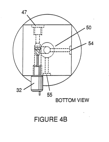 |
Figure 4, 4A and 4B show a side frontal cross-section and plan view from the top and bottom of a type of air gas processor such as 20 shown in Figure 2. In essence, the processor 40 of Figure 4 and its operation essentially correspond to the method and apparatus shown and described in my United States Letters Patent No. 4,826,581, (incorporated herein by reference), however, as used in the system of the present invention, the ambient air gases (not the combustible gas produced by the fuel cell), on a reduced scale, are charged and ionized and otherwise enhanced in energy before the ambient air gases are mixed with the fuel gas.
In the processor 40 shown in Figures 4, 4A and 4B a treatment chamber 50 is provided that encloses a set of batteries 41, 42, 43 of solid state lasers, e.g. 42, a, b, c, gd, etc., that are concentrically mounted around a charging cell formed from positively and negatively charged concentric rod 44 and cylinder rod 45 which are connected to an ionizing voltage source through terminals 54 and 55. Optical lens 46 concentrates the laser output to the gas flowing through the processor which also includes outlet port 47 for the energized air gas and a gas meter control 48. The electron extraction circuit 7 ionizes the incoming ambient air gases and consumes the electrons ejected from the gas atoms while the injected laser energy energizes the ionized gases to prevent the processed ambient air gases from reverting back to stable-state, as illustrated by Figure 7.
In the preferred embodiment of the invention a hydrogen fuel gas mixture is generated by the method of my aforesaid Letters Patent No. 4,936,961. That gas comprises a mixture of hydrogen, oxygen and other formerly-entrapped gases dissolved in water. It is the purpose of this invention, beginning with the hydrogen component of a fuel gas, to adapt hydrogen gas to the approximate burn rate of a fossil fuel for use in an internal combustion engine and to maintain the ratio of hydrogen to oxygen in the mixture at the most efficient 2:1 ratio. The system of the invention modulates the hydrogen component of the overall gas mixture such that the burn rate of the hydrogen-containing fuel mixture approximates that of a fossil fuel as illustrated in Figure 1.
While the invention of my Letters Patent No. 4,936,961 Produces a gas mixture including hydrogen, oxygen and all other gases that were formerly dissolved and entrapped in the water from which the hydrogen/oxygen gas mixture released by the process was formed, further modulation of the burn rate of this hydrogen fuel gas mixture occurs in the system of the present invention as a result of mixing with processed ambient air and the water vapor produced as a combustion exhaust product of the engine. In this regard, the rate of gas production in a water fuel cell introduction of hydrogen per se into the system if a water fuel cell is not used as a fuel source) determines the amount, per se, of hydrogen introduced into the system, but in the manner in which the hydrogen fuel is modulated, mixed with oxygen, and injected in optimal quantities and mixtures into the engine cylinder.
The regulation of the burn rate of the hydrogen fuel, which is of crucial importance in a hydrogen fueled internal combustion engine according to the system of the invention, is determined by the relative proportion of the mixture of the hydrogen containing fuel gas with ambient air or exhaust gas including water vapor that is recycled into the engine. The fuel gas mixture produced by the fuel cell intrinsically includes the optimum 2:1 ratio of hydrogen to oxygen. The mixture of hydrogen and non-combustible gas that modulates the burn rate of the hydrogen fuel mixture to that equivalent to gasoline must be achieved by the addition of the non-combustible gases and maintained uniformly over the range of engine operating speeds. This is accomplished by correlating the rate of fuel gas production from the water fuel cell with the introduction to the gas mixture of other non-combustible gases. This can be accomplished in a simplified engine by manual control involving manually sensed "look, touch and hear" impressions, as well as by complex electronic control means for more sophisticated engines. Maintenance of the consistency of the mixture by the management module prevents overloading of the engine with hydrogen and permits smooth running of the engine regardless of engine RPM or power load. The distributor and ignition system operates in a conventional mode to provide spark ignition of the fuel and oxidant mixture in the cylinder at the appropriate time in a piston reciprocating cycle that is otherwise also related to fuel intake and exhaust outlet sequences in the cycle. In the invention, however, two aspects of the injection of the fuel gas mixture into the cylinder at the intake cycle are controlled: (1) the 2:1 proportion of hydrogen to oxygen to "non-combustible" gases in the fuel intake mixture is maintained at a predetermined proportion such that the “burn rate” is maintained at the lowered predetermined rate corresponding to that of a fossil fuel; and (2) the quantity of the fuel mixture introduced to the cylinder at the intake of the cycle is the same per cycle regardless of engine RPM. Thus, although the rate of hydrogen production by the fuel cell must increase with higher engine RPM, the consumption of hydrogen, per cycle, remains constant. This constancy is maintained by the tuned gas meter control 18, 19 and by variation of the rate of gas production in the fuel cell as controlled by the gas management system CPU, ll. The gas meter control which provides the uniform delivery of the fuel gas mixture is determined by pulse signals generated by the distribution corresponding to each cycle of the engine.
Figure 6 represents the modulating effect on hydrogen density in a gas mixture, that the other large (non-combustible) gas molecules have in the hydrogen fuel gas that is accomplished by the invention. To wit, other gases dilute the hydrogen concentration in a given volume; the dilution in turn reduces the burn rate of the hydrogen per se component and enables the burn rate of the overall fuel gas mixture produced by system to approximate that of a fossil hydrocarbon fuel. As this modulation of the burn rate occurs, however, it is necessary to maintain the overall ratio of hydrogen to oxygen in the mixture as close to 2:1 aS possible to prevent overenrichment of the hydrogen in the fuel and the consequent shut down problems that result from an excess of hydrogen. Thus, inert water vapor exhaust gas, (¢.g., from valve 5 in Figure 2), as well as ambient air, is used as a dilutent. The introduction of ambient air may result in a proportional excess of oxygen in the mixture over the preferred ratio; however, excess oxygen insures complete combustion of the hydrogen component; to the extent that oxygen is in excess, it is a non-combustible dilutent. Too much of an oxygen excess may result in the production of undesirable NO, exhaust gases; however, this is not a significant problem and may be resolved in the engine system of Figure 2 by the introduction of more exhaust gas rather than air as a dilutent. When the burn rate of hydrogen is, however, reduced to that of a fossil fuel, the production of nitrogen oxides is reduced because the combustion temperature and rate is reduced.
Sensors of the system of Figure 2 monitor air pressure and temperature which affect the dilution of the hydrogen fuel. The management module CPU and controllers appropriately adjust the gas mixture components to maintain a uniform burn rate for the fuel mixture regardless of engine speed. For example, if the burn rate is not Maintained at a constant, the introduction of additional hydrogen by throttling the engine would disrupt the narrow combustion window of the gas resulting in engine inefficiency, roughness or shut down because of the overenrichment.
Distribution of the hydrogen gas (or the fuel gas mixture produced by the means of my aforesaid Letters Patent) within the engine system may be accomplished by an appropriately configured circuit of “quenching tubes", such aS. are shown in Figures 5 and 5B. The quenching tubes comprise a conduit of discrete small volumes such as formed in an open cell porous material formed in an otherwise solid, extending member. Typically, a plurality of conduits of microcell type material from .015 to .025 inch in diameter may be formed in a solid length having an outer diameter of approximately .378 inch in the manner shown in Figure 5. The conduit size specified is appropriate for a fuel gas having a burn rate equivalent to gasoline. Conduit diameters may be proportionately larger or smaller if the hydrogen concentration is further diluted or increased. The quenching tube prevents burn-back or flash-back of hydrogen in its delivery tube. Flash-back, a serious problem in conventional hydrogen gas transport systems, is eliminated by the quenching circuit tubes of the invention.
|
|
In the control system of the invention, all parameters are adjusted to maintain a uniform burn rate of the hydrogen containing fuel gas, which is the key to smooth engine operation. In the mechanical system shown in Figure 3, the characteristics of the hydrogen fuel are modified to adapt to load conditions, and the system works in a manner comparable to that of a conventional carburetor in a fossil fueled engine.
When used with a water fuel cell and the method of my aforesaid Letters Patent No. 4,936,961, a preferred management system includes a pulse generator for fuel gas production and includes a phase lock loop circuit that detects and scans a resonant frequency in the fuel cell generator and maintains that frequency. Such a system is described in my anticipated co-pending application.
From the foregoing description of the preferred embodiment, other variations and modifications of the system disclosed will be evident to those of skill in the art.
WHAT IS CLAIMED IS:
1. A gas fuel for an internal combustion engine comprising a mixture of gases including hydrogen, oxygen, and other gases that are not combustible with hydrogen in which the mixture includes a proportion of hydrogen to oxygen of approximately 2:1 and a predetermined density of hydrogen such that the burn rate of the mixture approximates that of a fossil fuel.
2. A management system for a fuel gas mixture containing hydrogen that is introduced as a fuel to an internal combustion engine consisting of:
means for monitoring the composition of a fuel gas mixture introduced into the engine such that the proportion of hydrogen to oxygen in the mixture is approximately 2:1; and
means for modulating the density of the hydrogen component of the introduced fuel gas mixture by the addition of other non-combustible gases to the mixture such that the burn rate of the fuel gas mixture approximates that of a fossil fuel.
3. The system of claim 1 in which the means for modulating includes a means for the mixing of a proportion of the exhaust gas of the engine into the fuel gas mixture introduced into the engine.
4. In a hydrogen fueled internal combustion engine, the improvement comprising: means for modulating the density of the hydrogen component of the fuel gas mixture such that the burn rate of the hydrogen is reduced to the approximate burn rate of a fossil fuel.
5. The improvement of Claim 4 which the modulating means includes means for mixing a hydrogen containing fuel gas with at least one of ambient air and exhaust gas from the engine.
6. Apparatus for the distribution of a fuel gas mixture containing a hydrogen gas component comprising a plurality of longitudinally extending conduits having an internal diameter of .015 to .025 inch intrinsically formed in an otherwise solid matter.
7. The apparatus of Claim 6 in which the conduit comprises a porous open celled foam.
8. A process for maintaining combustion in an internal combustion engine that is fueled by a fuel gas mixture containing hydrogen that is introduced as a fuel to consisting of:
monitoring the composition of a fuel gas mixture introduced into the engine such that the proportion of hydrogen to oxygen in the mixture is approximately 2:1;
modulating the density of the hydrogen component of the introduced fuel gas mixture by adding other non-combustible gases to the mixture such that the burn rate of the fuel gas. mixture introduced to the engine approximates the burn rate of a fossil fuel; and
Maintaining the volume of the introduced fuel gas mixture at a predetermined quantity for each operating cycle of the engine, regardless of engine operating speed.
9. The process of Claim 8 in which the step of modulating includes mixing a proportion of the exhaust gas of the internal combustion engine into the fuel gas mixture introduced into the engine.
10. The process of Claim 8 including the step of ionizing ambient air gases and introducing said ionized gases to the fuel gas mixture.
11. In a process for maintaining combustion in a hydrogen fueled internal combustion engine, the improvement comprising modulating the density of predetermined hydrogen component in a mixture of gases fed as fuel to the engine such that the burn rate of the hydrogen in the mixture is reduced to the approximate burn rate of a fossil fuel.
12. The process of Claim 11 including the mixing of a hydrogen containing fuel gas with at least one of ambient air and exhaust gas from the engine.