Japanese Patents
- Full Patent List
- JP 58-202352 - Hydrogen Gas Injection Apparatus for Internal Combustion Engine
- JP58207610A - Electric Particle Generator
- JP59038525A - Water/Hydrogen Gas/Oxygen Gas Generator with Controlled Flame of Hydrogen Gas
- JP59059889A - Apparatus for generating hydrogen gas and related gases from water
Full Patent List
JP 58-202352 - Hydrogen Gas Injection Apparatus for Internal Combustion Engine
Japanese Patent Office (JP)
Publication Number: JP 58-202352 (A)
Publication Date: November 25, 1983International Classification (Int. Cl.): F 02 M 21/02
Application Number: JP 258-23867
Filing Date: February 15, 1983
Priority Claim: US February 17, 1982 (US) 349185Title: Hydrogen Gas Injection Apparatus for Internal Combustion Engine
Applicant:
Stanley A. Meyer
3792 Broadway, Grove City, Ohio, USAInventor:
Stanley A. Meyer
3792 Broadway, Grove City, Ohio, USAAgent:
Law Firm: Nakamura & Associates (with 4 additional attorneys)
PDF Download: SMeyer-JP58202352A.pdf
Scope of the Claims:
(1) A housing for storing compressed gas, wherein the gas includes a natural gas mixture. This housing contains a pair of electrodes with non-conductive properties. These electrodes are arranged to apply direct current or high-voltage electric charges to the gas mixture in the housing. The system is designed to dissociate molecules of hydrogen and oxygen from the gas molecules. The residual gas is then collected and stored.
A method to extract hydrogen gas from the housing by controlling the pressure within the housing.
A mechanism to collect hydrogen gas generated within the housing through an outlet connected to the fuel combustion chamber.
A method to separate undesirable gas components from the gas generated, and return the remaining components to the housing.
A system to control the air-fuel mixture entering the combustion chamber by adjusting the volume of undesirable gas released.
(2) A device as described in (1), wherein the housing contains a variable valve to control the air pressure and the amount of hydrogen gas introduced to the combustion chamber.
(3) A method for separating hydrogen gas and oxygen gas within the housing, and transferring the gas through separate outlets.
(4) A system to use the separated hydrogen gas in combination with another fuel to create an air-fuel mixture suitable for combustion.
(5) A combustion device, wherein the rod mechanism connected to the tape-equipped rotating structure described above, and the port to which the tape-equipped rotating structure is connected, causes the displacement of said tape-equipped rotating structure.
(6) The gas mixture chamber, where it includes a hydrogen-oxygen gas injection device and also a non-explosive gas mixing device.
(7) The gas mixture chamber includes a trapping area in the upper and lower sections, and the hydrogen-oxygen gas mixture portion is stored in the trapping area.
(8) The surrounding air intake device includes a control mechanism, and a combustion device as described in claim (1), wherein the surrounding air and non-explosive gas mixture are directed into the chamber.
(9) ???
(10) The surrounding air intake device in claim (8), which allows the combustion chamber to intake oxygen and hydrogen gas into the trapping area for combustion.
(11) The combustion device in claim (1), wherein a control device is provided to connect the burner and the hydrogen-oxygen gas supply device, which controls the on/off operation of the burner to control the flow of gas.
(12) The combustion device in claim (1), wherein the control mechanism connected to the burner is pressure-regulated.
(13) A housing that surrounds the mixture chamber, having a first opening in the housing for air intake and a second opening in the housing to allow hydrogen gas captured in the mixture chamber to release into the atmosphere.
(14) The upper part of the hydrogen-oxygen gas generator includes a sealing area, wherein the hydrogen gas contained in it is stored at a predetermined amount.
(16) The method for connecting hydrogen-oxygen gas to the mixture chamber includes a directional valve as stated in claim (11) of the combustion system.
(17) The method for connecting hydrogen-oxygen gas to the mixture chamber, which includes an emergency device as stated in claim (11) of the combustion system.
(18) The gas burner described in claim (11) is an internal combustion engine, and the non-combustible exhaust gases are expelled through the engine's exhaust as stated in claim (11).
(19) The oil supply device, the multiple oil supply sources, and the oil spray are equipped as stated in claim (10) for supplying oil to the mixture chamber.
This invention relates to a new combustion device.
In U.S. Patent No. 4,302,807, issued on September 6, 1983, a hydrogen generation system is described, where water is dissociated into hydrogen and oxygen gas. The system passes water between two electrically non-conductive and non-oxidizing metallic plates, applies direct current voltage/electric fields of low energy to the water, causing the water molecules to dissociate into hydrogen and oxygen atoms. This process involves non-combustible, non-reactive electrolysis at low voltages, encouraging sub-atomic reactions. This system includes mechanisms that can separate hydrogen and oxygen gases from the water.
Additionally, in U.S. Patent No. 4,724,644, issued on May 5, 1987, a hydrogen-air gas treatment device is described. This patent discusses a system where hydrogen gas, along with non-combustible exhaust gases, is controlled to prevent combustion.
The "Hydrogen Air Purification Processing System" (Hydrogen Air-dation Processor System) is utilized to measure, mix, and compress gases. This system employs a rotary-type mechanical gas conversion device. When gas is converted, air is passed through an open-volume combustion chamber, and impurities and other substances from the existing gas are removed. Following this, the system adjusts the ratio of non-combustible gases and ensures the correct mixture by removing impurities, preparing the exact quantities of hydrogen gas and other combustible gases needed. In this manner, the system creates a new synthetic gas mixture. The volume of this synthetic gas is then measured, and the appropriate gas mixture for combustion is determined to ensure the correct amount of water gas is introduced to the combustion chamber. Additionally, the rotary mechanical gas conversion device regulates the exact volume of the synthetic gas to be produced.
The hydrogen-air gas treatment device described in U.S. Patent is a highly useful and practical system for a variety of purposes. Additionally, other U.S. Patents related to this system demonstrate a unique and simple hydrogen gas generation system.
This invention was filed on October 8, 1984.
In U.S. Patent No. 3,594,945, a mechanically operated device that can be applied to a combustion device has been disclosed. This combustion device is useful, for example, in the operation of a piston engine in an automobile. This disclosure relates to a hydrogen gas generator device that produces hydrogen and non-combustible gases (e.g., oxygen and nitrogen). The water gas and the non-combustible gases generated by the water gas production apparatus pass through a purification process and are then mixed together with non-combustible gases and air that are drawn into the combustion chamber by a control device. Following this, the mixed gas enters the combustion chamber where it is ignited. After combustion, the gas enters the mixing chamber, where the non-combustible gases are combined with flammable gases and vapor. As this occurs, a combustion process is formed, and this patent describes the practical application of this system, along with other examples of usage.
Now, the purpose of the current invention is to provide a combustion device that uses hydrogen and non-combustible gases.
The objective of this invention is to provide a combustion device that controls the temperature by regulating the mixture of hydrogen and non-combustible gases in advance.
Other objectives and features of the present invention will become apparent from the following description.
The preferred embodiment of the present invention is a combustion device that uses hydrogen gas, particularly in an automotive engine that operates the piston.
The hydrogen gas generator device used in this invention produces hydrogen gas, which is mixed with non-combustible gases and sent to the combustion chamber. Additionally, air is introduced into the mixing chamber, where it is further mixed with the hydrogen gas. This mixture is controlled in such a way that the combustion process is stabilized, and the combustion of hydrogen gas is controlled to adjust its burning speed and emission amount. By regulating the flow of hydrogen gas into the combustion chamber, and controlling the mixing of air and other gases, the combustion process can be optimized, and non-combustible gases can be utilized efficiently.
The hydrogen gas generator supports the ignition source for the combustion process.
The hydrogen gas generator includes a tank and is equipped with a pressure detection switch in the combustion chamber, as well as a position switch operated by other devices. Additionally, it has an electrical switch that operates when activated from a position different from other functions.
The simplified structure incorporates safety valves and emergency shutdown devices. This combination forms a complete system that can safely convert a hydrogen gas mixture into fuel for automotive engines, gasoline engines (or other fuel engines).
Below, the diagrams are used to explain the present invention.
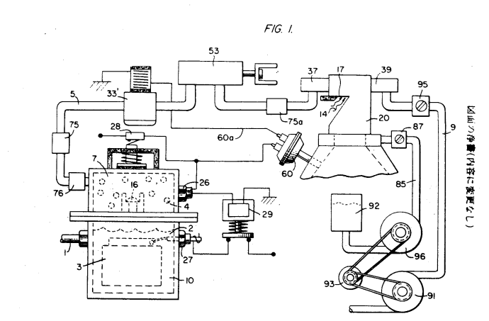
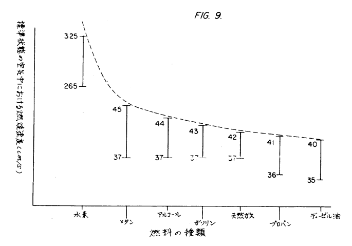
FIG. 1 illustrates the overall system of gas mixing and combustion in a combustion engine, particularly an automotive engine.
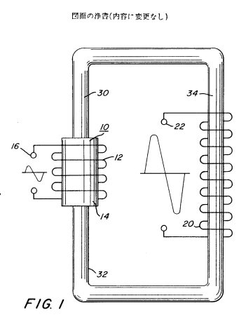
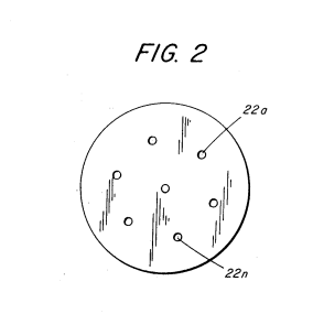
FIG. 2 shows the hydrogen supply source, which corresponds to the hydrogen gas generator 10 mentioned in the applicant’s prior U.S. patent publication. The device 10 contains storage components.
In FIG. 2, components related to the plates disclosed in the prior U.S. patent application are clearly displayed. At point 8 in FIG. 3, the direct current voltage/flow regulator is shown.
The upper part of the device 10, portion 7, is the hydrogen storage section, where the appropriate amount of hydrogen is kept under pressure.
In this way, during the start-up, water vapor generated by the hydrogen gas is supplemented with consumed water. The generator device is equipped with a conventional water replenishment pump. Additionally, the exhaust gas generator is constructed similarly to the one described in the applicant's previous patent application.
Safety valve 28 releases the excess gas generated. Additionally, switch 26 activates the hydrogen gas generator when the gas volume decreases, maintaining the required gas pressure level by operating the pressure switch.
The generated hydrogen gas is sent one way through the check valve 16 and pipe 5 to the gas mixing chamber 8, where it mixes with the combustible gas and is sent to the combustion chamber 9 through the supply pipe.
However, if the pipe 75 malfunctions and causes the hydrogen gas generator 10 to disconnect, a spark could ignite and trigger combustion in the generated hydrogen. In such cases, the spark is suppressed, and the combustion is extinguished.
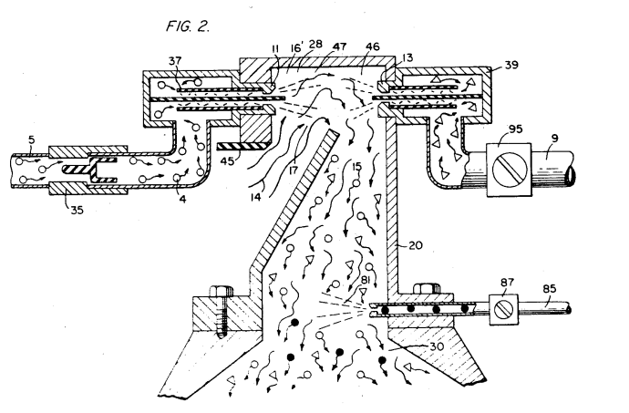
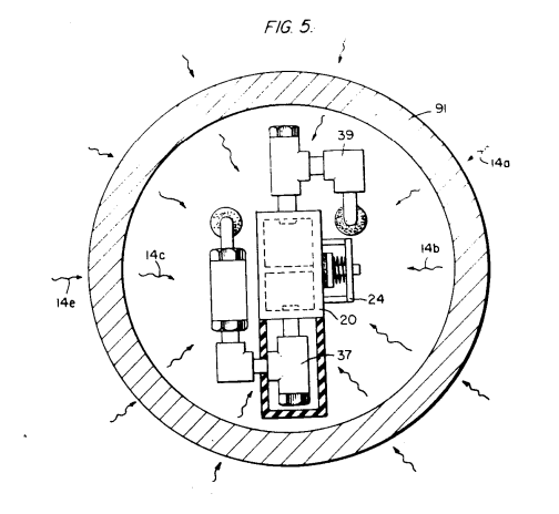
As explained with reference to figure 2, the hydrogen gas is sent through pipe 5, and the combustible gas is sent through pipe 9. Then, the mixed gas is conveyed to the mixing chamber 20 via the ejector or other mixing mechanisms, where atmospheric air intake section 14 is also set up.
The hydrogen gas passes through nozzle 11, through spray 16, and reaches the trap area 46 within the mixing chamber 20. Nozzle 11 is equipped with a small hole at the opening of the cooling device 37 to prevent any sparks from causing a flashback.
The non-combustible gas passes through nozzle 13 and is injected into the trap area 47 in the mixing chamber 20 as jet spray 17. The ignition device 39 works in conjunction with the emergency valve 37.
When the gas is generated, it activates the combustion in the combustion chamber. Additionally, the gas exhaust pipe within the exhaust system releases the non-combustible gas along with the exhaust gas, which ensures safe operation.
At first, oxygen and/or non-combustible gas can be supplied independently or simultaneously to ensure a constant supply. Furthermore, referring to figure 2, the trap area 47 for gas has a suitable size for the nearby section. When hydrogen gas is introduced into the air, the hydrogen rises and is captured within area 47. The size of area 47 ensures that, during the start of the combustion engine, the temporarily generated spark will collect a sufficient amount of hydrogen gas to ignite.
The introduction of hydrogen gas into the trap area 47 helps prevent ignition delays. Hydrogen gas rises at a much faster rate than oxygen (or non-combustible gas), rising at a rate three times faster or even more. This allows hydrogen gas to enter the trap area (liquid section) much quicker, making it easier to rise into the air, compared to other heavier gases.
In the configuration with the ejector system, hydrogen gas is strongly ejected downward toward the air intake section 15. At the same time, as hydrogen gas rises strongly upwards, it mixes thoroughly in the turbulence created by this combination of downward and upward flows.
Non-combustible gas and sealed air (oxygen) passing through passage 9 have a controlled ratio suitable for each engine. The amount of non-combustible gas is adjusted by regulating valve 45, and adjusting the amount of sealed air allows for the proper combustion mixture to be determined and maintained. The system ensures that non-combustible gas is controlled by the engine's exhaust gas, and the intake air volume is regulated according to the engine, thereby maintaining the non-combustible gas supply relative to the engine's acceleration.
The sealed air and non-combustible gas mixture becomes a carrier for hydrogen gas. That is, hydrogen gas is mixed with the sealed air/non-combustible gas combination. By adjusting the volume of hydrogen gas mixed with sealed air/non-combustible gas, the engine's revolution rate is controlled.
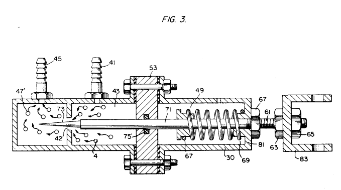
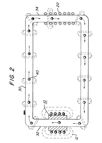
Referring to figure 3, the details of the control mechanism for regulating the combustion mixture is clearly demonstrated in paragraph 53.
Hydrogen gas 4 enters the system through gas inlet 41 and moves to tube 43.
Hydrogen gas passes through valve 43, enters chamber 43, and then goes through port 42 into chamber 47. The amount of gas flowing from chamber 43 to chamber 47 is regulated by controlling the opening of port 42.
The opening of the port is controlled by inserting pin 73 into the wedge-shaped groove. Pin 73 is fixed at the end of rod 71. Rod 71 passes through support 5, moves through housing 30, and reaches the manual driving mechanism 83 through manual control system 81.
Spring 49 holds rod 71 and pin 73 in place relative to the opening 42. When the mechanism 83 operates, pin 73 is pulled away from the opening 42, allowing more gas to flow from chamber 43 into chamber 47.
Stoppers 67 and 69 hold spring 49 in the default position. The fixed position of pin 73 relative to the opening 42 is connected to nut 13 attached to rod 61, which is fixed by stoppers 67 and 69. This mechanism controls the idle speed and regulates combustion under low-load operation by adjusting the size of the wedge.
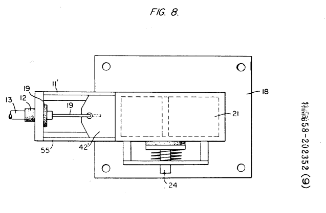
Gas flows from chamber 43 to chamber 47. In the diagram, the air volume control device for regulating the amount of air sent to chamber 20 is illustrated. Plate 21 is attached to board 18, and its end is fixed to port 11. Control plate 42 is equipped with an automatic return spring. The position of control plate 42 relative to port 12 is controlled by the control device connected to lever 19. If an abnormal combustion condition occurs in chamber 20, safety valve 24 is activated.
As shown in Figure 6, when hydrogen gas passes through chamber 20 at high pressure, any water collected at filter 34 will be discharged through line 36, and the remaining hydrogen gas will be safely released into the atmosphere.
When an abnormal combustion condition is detected inside chamber 20, safety valve 33 is activated, and any hydrogen remaining is expelled from the system to prevent further combustion.
The gas control system illustrated regulates the flow of hydrogen (combustible gas) to the burner. In the case of a burner, a gas control valve 53 (gas inlet) is provided to regulate the flow of hydrogen gas to the burner. The details of valve 53 are explained in Figure 3. The air intake section 14, as explained in Figure 8, is controlled by an air control valve 55 that regulates the flow of air. This mechanism allows proper air supply to the burner.
To maintain a stable pressure in the hydrogen storage tank during the engine's on/off operation, the gas control valve works in conjunction with vacuum-operated switch 33'. This ensures stable gas supply during startup and normal operation, as well as during periods when the engine is running.
Switch 33' operates in connection with vacuum control switch 60, which is activated when the engine is in operation. If the vacuum falls during engine idle, switch 33' responds accordingly.
When switch 60 is released, switch 33' is activated, stopping the flow of hydrogen gas to the control valve 53. When safety valve 28 detects a low pressure, solenoid 29 is activated. The solenoid works through pressure switch 26 and restricts the backflow of hydrogen gas by controlling the pressure at the rear end of the hydrogen generator. When the solenoid 29 is activated by electric power, hydrogen gas flows out of control valve 16, through pipe 5, and is supplied to the burner.
The differential pressure of the hydrogen gas relative to the gas mixture chamber is approximately 0.5 to 0.7 kg/cm² (30 pounds per square inch or 5 psi). When the hydrogen generator 10 reaches a critical level, pressure switch 26 starts regulating the pressure supply to the hydrogen generator. If the pressure exceeds a certain level, safety valve 28 will activate, and the power supply will be shut down to prevent any hazards, shutting down the entire system for safety.
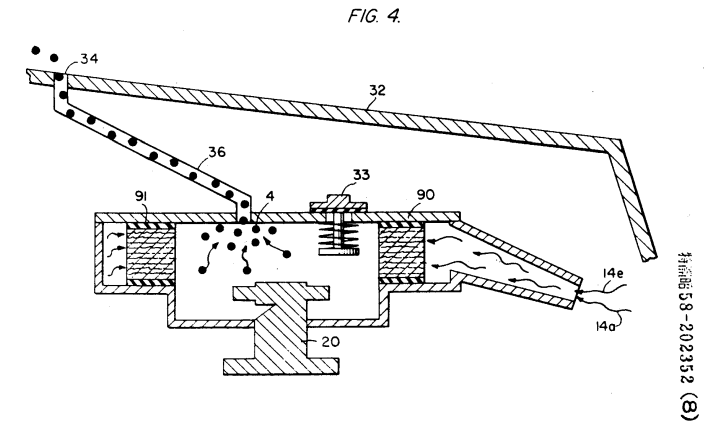
Figure 8 shows a four-stage enclosed combustion system with an upper lid separating the internal combustion chamber.
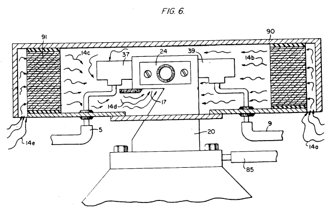
In this preferred embodiment, the apparatus is equipped with housing 90, which contains the air intake sections 14a and 14b. The air passes through filter 91 attached to sections 14b and 14c and then flows into the intake section 14d of the mixing chamber 20. Water flows through pipe 5 and passes through cooling device 37 before entering the mixing chamber 20. The non-combustible gas from the combustion chamber passes through cooling device 39 and then enters the mixing chamber 20.
Note: Figure 8 illustrates the mechanical details of the components inside mixing chamber 20, which are also shown in another diagram.
Returning to Figure 3, in this diagram, valve 93, which is activated by the engine, regulates the flow of non-combustible gas through passage 91. Attached to valve 93 is filter 95, and also a lever 98 that is mechanically linked to throttle 92. Additionally, pipe 87 connects to mixing chamber 20, regulating the flow of non-combustible gas during engine operation.
The oil supply valve 85 regulates the flow of the oil atomizer, delivering it into chamber 20 for combustion.
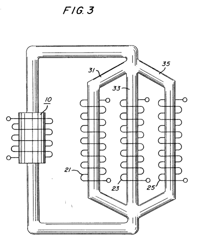
Now, examining the characteristics of hydrogen gas, the system's operation, and safety, several research papers provide important insights. One such paper is "Selected Properties of Hydrogen (Engineering Design Data)" published in February 1981 by the National Bureau of Standards.
This research primarily discusses the high cost of hydrogen generation and its challenges. Additionally, the papers explain that hydrogen gas poses safety concerns when used in industrial applications, especially regarding its low ignition energy.
Figure 9 compares the ignition energy of hydrogen with that of other fuels such as alcohol, propane, butane, methane, and diesel oil. It demonstrates that hydrogen's ignition energy is significantly lower than that of other fuels.
In order to achieve a high combustion speed with hydrogen gas, traditional researchers have not considered hydrogen as a replacement fuel. Furthermore, even if engines were designed to handle such high combustion speeds, safety concerns regarding explosion hazards make it impractical for commercial use.
This invention, as mentioned earlier, solves the above-mentioned problems when hydrogen is used in conventional commercial engines. First, by referring to the U.S. Patent documentation, the cost of hydrogen gas production is low. Additionally, as shown in the prior art, hydrogen gas combustion is controlled, thus allowing safe use. The U.S. Patent documentation explains that this control is achieved through methods, showing a feasible and practical approach.
Thus, this invention offers a suitable application for industrial engines using hydrogen fuel by solving the previously noted safety concerns.
A practical device for applying hydrogen gas generators to combustion engines has been developed. This invention regulates the flow of hydrogen gas in a controlled manner, sends the reduced hydrogen gas mixture to the combustion chamber, and minimizes the combustion speed. Thus, using this device ensures the same level of safety as when using other fuels.
Furthermore, as an experimental advantage, this device can be adapted to work with any type of internal combustion engine, regardless of its design or fuel type, by operating exclusively on hydrogen gas. Hydrogen gas, unlike chemical compounds, is very low pressure and lightweight. The combustion speed of hydrogen gas is lower than that of typical fuel combustion systems. Above all, all the previous considerations, with safety features in mind, guarantee that this system operates safely, even when using hydrogen gas in conventional automatic systems.
The above explanation applies equally to both combustible and non-combustible gases. The system ensures safety by controlling the gas flow in a simple and safe manner.
As mentioned earlier, regarding the hydrogen storage area labeled as region 7, the term "storage" does not imply long-term storage in the academic sense. In fact, this region is more accurately described as a temporary retention area. Region 7 holds sufficient hydrogen for the initiation of combustion when needed.
Other applications and examples related to this invention have been explained in the previous sections. It is important to understand that the described invention is not limited to these technical boundaries but can undergo various modifications within the scope of the claims.
Explanation of Figures
Figure 1 is a block diagram showing a general practical embodiment of the device described in this invention.
Figure 2 illustrates a special hydrogen radiation device featured in the practical embodiment of the invention.
Figure 3 shows a configuration diagram of a fuel injection control device, which is also part of the special embodiment of the invention.
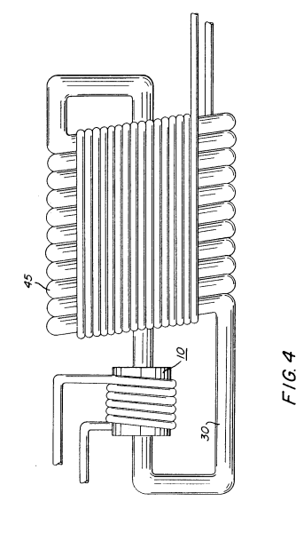
Figure 4 depicts the invention applied to an automatic combustion system using non-combustible fuel.
Figure 5 shows the plan view of the fuel injection device used in this invention.
Figure 6 shows the side sectional view of the fuel injection device of this invention.
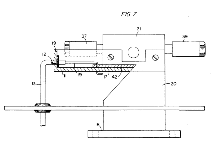
Figure 7 shows the side sectional view of the fuel mixing chamber used in this invention.
Figure 8 shows the sectional view of the fuel mixing chamber, which includes an air intake.
Figure 9 is a graph illustrating the combustion efficiency of various fuels for reference.
List of parts:
1... Water supply source 3... Plate (injector plate) 4... Hydrogen gas 7... Hydrogen storage area 10... Hydrogen gas generation device 20... Gas mixing chamber
Procedural Amendment Document (Form)
Date: Showa 58 (1983) June 30Patent Office Notice:
Case Number:
Showa 58 Year Application No. 23667Title of the Invention:
Internal Combustion Engine Hydrogen Gas Injection DeviceApplicant (Person making the correction):
Relationship to the case: Applicant
Name: Stanley A. MeyerAgent:
Address: Tokyo, Chiyoda-ku, Kanda-Jinbocho 3-1-1 (Phone: 211-8741)
Name: Attorney Nakamura (Attorney Number: 58906)Date of Correction Order:
Showa 58 (1983) May 31Scope of the Correction:
Entire DocumentContent of the Correction:
As indicated in the attached document
[Corrected to read: Internal Combustion Engine Hydrogen Gas Injection Device]
|
|
|
|
|
|
|
|
|
|
|
|
|
|
|
|
JP58207610A - Electric Particle Generator
Japan Patent Office (JP)
Patent Application Publication
(Application A)
Patent Application Publication No.:
Showa 58-207610Patent Application Date:
Showa 58 (1983), December 3Application Number:
Showa 58-23664
February 15, 1983Priority Claim:
1982 April 9, USA No. 367051Title of the Invention:
Electric Particle GeneratorApplicant:
Stanley A. Meyer
Grove City, Ohio 43123, USAAgent:
Attorney Nakamura
Title of the Invention
Electric Particle Generator
Scope of Patent Claims
(1) An electric particle generator equipped with a particle accelerator at the end of a tube through which non-conductive magnetic gas flows, and incorporating ionization elements inserted into the unit, which work together with the particle accelerator.
(2) The electric particle generator described in claim 1, where the ionization element operates with low input voltage in the second chamber, and the voltage/electromagnetic field is used to extract and utilize energy from the gas.
(3) The electric particle generator described in claim 1, wherein a second electrode that extracts the ionized particles from the first chamber is installed and operates to capture the energy released.
(4) The ionization element described in claim 1, wherein the element is solid in structure.
(5) The ionization element described in claim 1, wherein the element is a liquid.
(6) The electric particle generator described in claim 1, wherein the particle accelerator is driven by a magnetic coil.
(7) The electric particle generator described in claim 6, wherein the magnetic coil is designed to generate a low input voltage into the first chamber.
(8) The electric particle generator described in claim 7, wherein the low input voltage and the magnitude of electromagnetic force generated by the second coil control the size of the voltage output.
(9) The electric particle generator described in claim 7, wherein the low input voltage is further enhanced by the ionization process.
An electric particle generator in which the first coil’s input voltage is alternating current and operates at a constant frequency, wherein the magnitude of the input voltage/alternating current is low voltage.
An electric particle generator in which the first coil’s input voltage is pulsating direct current and operates at a low voltage.
An electric particle generator in which the first coil’s input voltage is variable, wherein the magnitude of the input voltage/alternating current is modulated to control the output.
An electric particle generator that includes a second chamber where the input voltage is lower than in the first coil and accelerates the ionized particles.
An electric particle generator in which the chamber is separated into three parts.
Each part is connected in series to a brush, and the second coil is connected to each of the brush terminals, with each coil being phased separately. This creates a three-phase alternating current effect.
An electric particle generator where the ionization element is filled with water and has an ionized structure that contributes to enhanced electromagnetic force.
An electric particle generator that is capable of providing particle acceleration by the mechanism of alternating current and low voltage within the chamber.
An electric particle generator in which the first coil and the electromagnetic force created by it send the ionized particles through a tube to a designated location.
Magnetic Field Generator
The magnetic field generator emits magnetic fields to induce particle ionization, passing through a pipe where ionized particles are accelerated. This system magnifies the effect of ionized particles as they pass through the magnetic field system.
3. Detailed Description of the Invention
According to traditional teachings, a magnetic field induces voltage/electric current when passed through, or by passing the magnetic field to a coil or a second system, voltage generation occurs. The basic principle behind this is detailed.
Additionally, in this invention, the first coil element induces voltage/electric current as it moves and reacts to other attached elements. This method of inducing voltage from a moving coil element can result in further acceleration by causing oscillation between the coils.
Thus, the induced voltage from both primary and secondary coils can be magnified. This magnetic field enhancement technique accelerates the voltage generated between the coils as the first coil moves in relation to the second coil. Other charged particles move in sync with these oscillations, which also produce oscillating voltage/current patterns.
This basic principle is central to the invention. The device utilizes magnetic induction to generate low-voltage input and enhances this through interaction between the first and second coils. The first coil induces a current which is then further accelerated by the second coil's voltage, causing an amplified output that can drive various external components.
However, the specific characteristic of this design is the inclusion of an ionization element, where particles such as ions or electrons are placed in a non-metallic (such as a sealed loop) tube. This element enhances the interaction between magnetic fields and charged particles, leading to the movement and acceleration of particles through the system.
As these particles accelerate, the voltage is further amplified through the reaction between the primary and secondary coils. The result is an increase in the overall electrical potential, allowing for a higher output voltage and the efficient generation of electrical energy.
The objectives of the present invention are as follows:
The first objective of the present invention is to provide a power generation device that can be used in either a single-phase or three-phase electric power system.
The second objective is to provide a device that can generate charged particles via particle acceleration.
The third objective is to provide a device that releases exhaust gases to an external environment only when temporary pressure buildup occurs.
The first and second objectives are achieved by utilizing the first coil’s magnetic field and the particle acceleration element (sensor 10), plasma detection device 14, and voltage detection chip 16. These components are part of a system designed to generate charged particles inside the tube, using the magnetic coil to accelerate particles.
Additionally, the second coil 20 is installed along the outer part of the tube and interacts with the first coil to create a plasma acceleration effect.
By using voltage taps 22, electricity can be induced into the secondary coil 20, making the use of electricity possible.
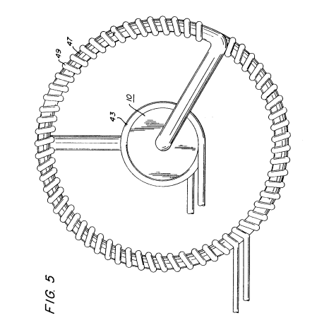
Magnetic element 40 is installed inside pipe 30, as shown in the second figure. This element 40 is free to move. When this element moves, it will float and separate charged particles in the plasma, expelling electrons and ions from the mixture. Additionally, it will further support the transition to the preferred state, ensuring that the particles in the plasma are properly separated.
As the particles move through the coils, acceleration increases, and this magnet accelerates the particles as they transition between different layers. The magnetic element and the particles work together to allow for smooth acceleration.
Furthermore, this movement creates a temperature drop, allowing the particles to reach maximum velocity. The interaction of the electric fields between the particles also changes as the input voltage increases or decreases, influencing the particle’s direction.
As a result, the voltage and current output of the secondary coil 20 will change. The output voltage/current of the secondary transformer coil 20 is influenced by the taps 22.
The only method for configuring this system is to use the loops 1 and 2. The secondary coil circuit in the third figure represents a combination of the charged particles. These particles are shown in the discharge tubes, forming magnetic fields in response to the plasma. Taps 21, 23, and 25 are attached to separate parts of the coil.
The coils with taps 21, 23, and 25 are connected to corresponding parts of the circuit, as shown in the first and second diagrams. The connected pipe releases the input-output energy, combining with the magnetic fields of the secondary coil to form a steady three-phase electric system.
In the fourth figure, the charged particle system causes the charged plasma to be isolated physically in the magnetic fields to enhance the discharge system's overall performance.
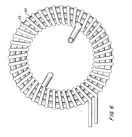
The insulation coating 45 completely covers the entire electric coil and the pipe 30. Figure 4 shows that as the provided electric energy stabilizes, the coil windings increase, and the voltage/current power becomes stronger.
The physical properties of water, such as the dielectric constant and the surface tension of hydrogen, are effectively utilized in this configuration. As a result, large-diameter pipe-based secondary current transformers with multi-turn coil windings are used.
Figure 6 explains the general layout, with the central particle accelerator tube 41 utilizing the entire particle acceleration structure. The device works by using the primary and secondary coils inside a two-phase structure with coil windings. The taps 53, installed in alignment with the coil windings, form a structure of mutual interaction between the coils.
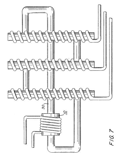
In summary, Figures 1, 2, and 3, combined with particle acceleration tube 41 and pipe-based structures, enhance the entire system’s efficiency. Additionally, coil windings are placed in parallel rows, with each part of the system holding a crucial role in generating power.
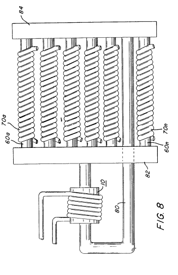
There are three secondary coil windings, and tube 30 passes through all three of these secondary windings in a straight arrangement. Figure 7 illustrates the structural configuration of the coil windings. The windings of the pickup coil are lined up in a straight arrangement, with tube 80 running through them in a linear path. The principle of these windings is based on a numerical setup with 7600–60nC indicating an output capacity of 88 and providing a distance ratio of M84 on the coil. The secondary coil windings 70A and 70B are arranged in series, respectively connected to the device.
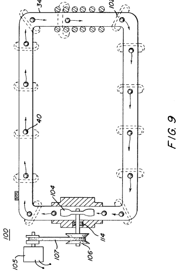
The particle acceleration tube 104 is installed along with its particle accelerator tube 110 to create a primary structure. Figure 9 shows that the particle acceleration device achieves speeds of 1100 meters per second. In this implementation, the particle device 102 is enclosed within the magnet tube 110, and the detector magnet sensor 106 reads the magnetic field produced. The energy acceleration tube 104 increases the power and, through the coupling system, adds frequency modulation using device 112, combined with the recalibration system 114 located at position 102.
When particles rotate around the secondary coil, electrical power/voltage is generated in the secondary coil. This suggests that particles do not just revolve around the coil but also induce electromagnetic cutting in the coil's magnetic field.
As previously explained, pipe 30 is a non-magnetic pipe. This is important as this pipe cannot have magnetic properties. Furthermore, pipe 30 provides the capability to rotate through a certain rotational mechanism. This rotation induces electromagnetism, and these rotating particles are the source of this phenomenon.
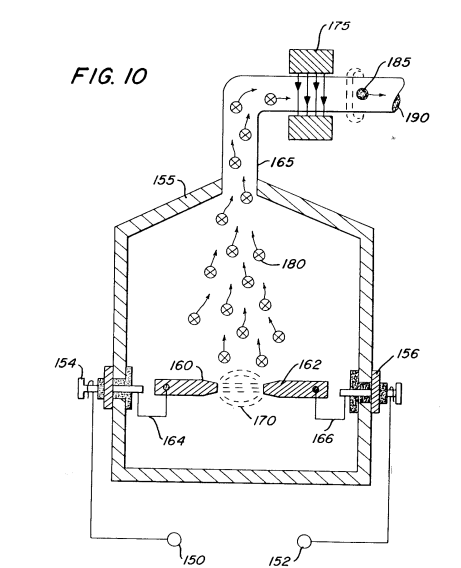
The next part explains various embodiments of the coil winding concept. In one embodiment of this invention, the coil is surrounded by a sealed magnetic tube, which generates electrical power/voltage in the coil. Figure 10 shows the electrical generation and winding process, designed to adjust to various operational steps while increasing the magnetic and inductive capacity.
Channel 155 is made of magnetizable (magnetization-capable) material and serves as the magnetic core.
When voltage 160 is applied to particle 162, the charged magnetic particle escapes from the magnetic pole and moves upward to particle 180. Particle 180 is elevated into a non-magnetic space, and when the magnetic field force is applied to each particle, it passes through magnetic element 175. All the magnetic charges pass through the demagnetizing coil 185, reaching the magnetic generator unit 190.
In the above mentioned embodiment and the simplified illustrations shown in Figures 1 and 2, the rotational acceleration rate is increased by adjusting the input of each particle into the magnetic core. This rotational input is proportional to the secondary voltage/current power output and sent to the voltage power capacitor 200. This is an important feature of the present invention.
The advantage is that voltage conversion is performed depending on whether the input voltage is DC or AC. When the input voltage is DC, the output voltage will also be DC. On the other hand, when the input voltage is AC, the output voltage will be AC. Furthermore, when a pulse voltage is used, a pulse output voltage will be generated. In this way, the present invention adjusts the input voltage and outputs the desired voltage based on the type of input voltage used.
As described in the preferred embodiment above, this invention may vary depending on the scope of the claims and modifications as outlined in section 4.0 below.
Section 4.0 illustrates the principles of the invention through partial diagrams. Figure 1 shows a typical three-phase system circuit configuration of the present invention. In Figure 3, another preferred embodiment of the invention is shown with an extended circuit design. This configuration includes separate systems for each voltage input.
Figure 9 explains a different configuration for the magnetic acceleration device to generate magnetic particles. Figure 10 shows the magnetic particle generator configuration used in the present invention.
Figure 10 Particle Acceleration Device
Tap Method 20, 21, 23, 25, 53, 70 ~ 70n...
Second Coil Winding Line 30, 31, 33, 35, 47...
Non-Magnetic State Coil 102, 180...
Magnetic Element 106...
Particle Acceleration Process 150, 152...
Voltage Power Supply 155...
Channel 160, 162...
Magnetic Material Manufacturing 165...
Pipe 175...
Magnetic Particle Generator
Procedure Amendment Document (Form)
Date: Showa 58 (1983) June 30Patent Office Document Number
Showa 58 Year Application Number 23664
Title of the Invention: Electric Particle GeneratorApplicant for Amendment: Submitter:Name: Stanley A. Meyer
Agent: Address: Tokyo Chiyoda Ward Iidabashi 3-Chome, Number 1-1(Law Firm Name and Phone Number)Name: Attorney Nakamura Tetsu (Registration Number 5995)
Date of Amendment Order: Showa 58 (1983) May 31
Content of Amendment: Full diagram revision
Details of Amendment: As per the attached diagram, the diagram content has been changed.
|
|
|
|
|
|
|
|
|
|
|
|
|
|
|
|
JP59038525A - Water/Hydrogen Gas/Oxygen Gas Generator with Controlled Flame of Hydrogen Gas
Japan Patent Office (JP)
Publication of Patent Application (A)
Publication Number: Showa 59-38525
Publication Date: Showa 59 (1984) March 2
Application Number: Showa 58 (1983) Number 23665
Title of the Invention:
Water/Hydrogen Gas/Oxygen Gas Generator with Controlled Flame of Hydrogen GasApplicant:
Stanley A. Meyer
3792 Broadway, Grove City, Ohio 43123, USAPriority Claim:
Filed on August 25, 1982, in the United States
Application Number: 411977Agent:
Attorney Nakamura Tetsu
(With 4 assistants)
Detailed Description of the Invention
1. Title of the Invention:
Water/Hydrogen Gas/Oxygen Gas Generator with Controlled Flame of Hydrogen Gas
2. Scope of the Patent Claim:
(1) A water/hydrogen gas/oxygen gas generator that produces these gases while controlling and maintaining the flame produced by hydrogen gas. This apparatus uses a low voltage, low current, and low frequency applied to a pair of stainless-steel electrodes positioned in water to separate water into hydrogen and oxygen gases. Moreover, it uses a gas collection mechanism to retrieve the non-combustible materials and water vapor. Additionally, the invention includes a mechanism to mix the hydrogen gas with water vapor and non-combustible gases before introducing them into the combustion chamber. The size and shape of the nozzle determines the amount of gas delivered, and the system incorporates a mechanism to regulate the combustion flame of the hydrogen gas.
(2) A water/hydrogen gas/oxygen gas generator as described in claim (1), wherein the non-combustible gas is compressed and mixed with the hydrogen gas and oxygen gas.
(3) A water/hydrogen gas/oxygen gas generator as described in claim (2), where the gas mixing mechanism further includes a chamber for mixing hydrogen gas, oxygen gas, and non-combustible gases with water vapor and non-combustible gas, allowing for a controlled mixture.
(4) A water/hydrogen gas/oxygen gas generator as described in claim (3), wherein the chamber includes an inlet to control the flow of gases into the chamber and a mechanism for further regulating the mixture to produce an optimal flame.
(5) A water/hydrogen gas/oxygen gas generator as described in claim (4), wherein the nozzle has a specific size and shape to control the output of the gas mixture, and the size of the flame is determined by the nozzle.
(6) A water/hydrogen gas/oxygen gas generator as described in claim (5), where the size and shape of the nozzle is maintained by multiple ports, allowing the flame size to be proportionally enlarged.
(7) A water/hydrogen gas/oxygen gas generator as described in claim (6), where the port size and shape are maintained by multiple ports, enabling the flame to be enlarged in proportion to the size.
3. Detailed Description of the Invention
This invention pertains to a water/hydrogen gas/oxygen gas generation apparatus.
The method described in U.S. Patent 302,807 (dated September 6, 1981), also employed in this invention, involves generating hydrogen and oxygen gases from water.
The method described uses conductive metal plates with non-oxidizing properties to separate hydrogen atoms from water molecules. These metal plates are exposed to low-voltage, low-current, and low-frequency electric fields to destabilize the water molecules, allowing the hydrogen and oxygen atoms to separate. This induces a sub-atomic (sub-atomic) reaction, allowing the release of hydrogen and oxygen atoms from water. The hydrogen atom is separated from the oxygen atom and is then released as hydrogen gas, which is collected by the gas recovery system.
The energy required for this process is supplied by an electric field, where the attraction force acts on the hydrogen gas, drawing it toward the plates. Meanwhile, the separated gas is drawn into the recovery system.
The separated hydrogen gas is then used as a fuel, functioning through the application of low-energy electric fields.
(dynamic) and serves to transform the hydrogen and oxygen atoms into molecules. The excitation from water molecules increases the vibration of the hydrogen and oxygen atoms.
The apparatus disclosed in U.S. Patent 2,662,244 (dated May 1, 1953) describes a water/hydrogen/oxygen gas generation device using a certain method to produce hydrogen and oxygen gases.
In the process, an electric field is applied to water, and the excitation generated allows the hydrogen and oxygen atoms to separate. This method generates a flame and is designed to produce flames by utilizing these separated gases.
When used, the device must ensure that water is constantly replenished to maintain a steady flow of hydrogen gas. The output can be controlled to vary from approximately 3 to 5 cm/sec. This rate can be adjusted based on operational parameters.
The hydrogen gas generated is collected using specific mechanisms to ensure that no unnecessary gases are trapped. Thus, the generated hydrogen gas is systematically fed into the intended systems.
To maintain the flame, it is necessary to carefully control the water flow in order to minimize the presence of excess water vapor.
Water naturally exists in various forms, such as distilled water, brine, seawater, and fresh water, but it is important to know how to prepare water to achieve optimal conditions for the system being used. Additionally, in this case, the mixture should include a sufficient amount of hydrogen and oxygen gases to ensure that the natural properties of water do not interfere with the output from the apparatus.
The generated gas is collected via lines connected to collection channels, ensuring that the size of the hydrogen gas generated is appropriate for the intended applications. This can be achieved by adjusting the input conditions to regulate the size and shape of the gas output.
The primary goal of this system is to utilize water as the primary material for generating hydrogen gas.
In addition to hydrogen and oxygen, this system can also supply fresh water/hydrogen gas generation, making it possible to maintain combustion using these gases.
Another objective of this invention is to provide hydrogen gas and oxygen gas to create a new type of water/hydrogen gas generation system, which helps minimize the combustion of other non-hydrogen gases.
The primary goal of this invention is to provide a means for generating non-hydrogen gas by supplying water and oxygen, and then using the energy produced to maintain combustion.
In the present example, the device described will be explained in detail below. The hydrogen and oxygen generated will be combined to provide a combustible mixture.
In the configuration illustrated in this example, the output from the generating device is introduced into a reaction chamber where the generated gases will be processed. The processed output will then be directed to a nozzle for application.
The power is supplied through the electrodes of the generator, which are connected to the output terminals. In this manner, the hydrogen and oxygen will be combined within a reaction chamber that is located above the electrodes.
Furthermore, the methods of maintaining the combination of hydrogen and oxygen in this chamber are essential, as they need to be continuously supplied to ensure efficient combustion. The system requires specific management of these gases to maintain stability.
Natural water sources, such as rivers, lakes, or oceans, can be utilized in this system. Additionally, the use of a spray atomizer is preferred, which aids in the effective integration of hydrogen and oxygen gases for combustion purposes.
The system described utilizes various methodologies to ensure that the gases are effectively combined and delivered for optimal energy production. Therefore, it is crucial to maintain the specific conditions necessary for the effective operation of this innovative water/hydrogen gas generation technology.
In this way, hydrogen gas and oxygen gas are generated and burned together with the water gas.
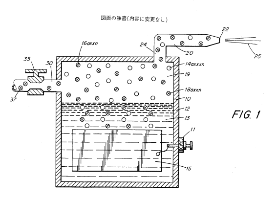
An example of using water is when water is introduced into the reactor at channel 16. Here, hydrogen gas produced in the generator 10 at inlet 18 is mixed with oxygen gas from channel 18.
Next, gas is passed through line 20 and valve 22, allowing it to flow and mixing the gases, yielding a combined gas mixture, which is held under a pressure of approximately 25.
In conjunction with the water flowing through channel 14, the water vapor will further enhance the production of hydrogen gas, effectively increasing the efficiency of the process. The addition of water to the hydrogen gas system within the generator channel 19 assists in reducing impurities in the gas.
The nozzle 20 is connected to the generator 10 through line 24 and channel 19, allowing for gas to be drawn from the reservoir at port 22. The pressure of the gas within the channel 19 is maintained at a considerable level.
However, the amount of gas that can be produced in this manner is limited. Therefore, it is crucial to consider the potential for introducing water vapor. Additionally, if water is allowed to flow into the system, it will carry with it a mixture of gaseous and liquid components.
Moreover, water will enhance the process and facilitate the mixing of gases. The overall effect is that the gas pressure can be increased, thereby improving the efficiency of the gas generation system.
The pressure is directly related to the amount of power generated.
The pressure of the water, which contains the gas in channel 19, can increase. However, the effectiveness of this increase is tied to the capacity of port 22. It is uncertain whether the pressure that can be achieved is sufficient to maintain the desired outcomes. Nevertheless, if the port is reduced, the system can produce a higher concentration of gas.
Additionally, if the pressure increases significantly, it may result in a larger quantity of gas being produced. Ports that have specific targets, such as port 22, are crucial for controlling the flow. If necessary, adjustments can be made to maintain appropriate levels, ensuring that sufficient conditions for gas production are met.
Detailed Description of the Invention
This invention relates to a device that generates hydrogen gas and oxygen gas by electrolysis of water. This invention is related to U.S. Patent No. 302,807 (issued on June 6, 1981), which pertains to methods of generating hydrogen gas and oxygen gas for use in various applications.
In the prior art, methods for generating hydrogen and oxygen gases by electrolysis have been developed, using certain methods that introduce water molecules, thereby separating the two types of gas. The method outlined in this invention uses the above to effectively generate hydrogen and oxygen gas.
The specific components involved in the electrolysis process of water, and the hydrogen and oxygen gases produced from this process are detailed in the following.
- The apparatus includes a basic electrolytic chamber for generating hydrogen and oxygen gas.
- The electrolytic chamber can vary in size and shape and may utilize various types of electrodes.
- It has been shown that using non-ionic water and certain catalysts can improve the efficiency of the process.
- The characteristics of the hydrogen and oxygen gases produced by the method described can vary based on conditions like temperature and pressure.
Supplementary Correction Document (Format)
1. Title of Application: Apparatus for generating hydrogen/oxygen gas from water
2. Document Number: Showa 58 (1983) Special No. 23667
3. Corrected by: Applicant
Name: Stanley Meyer
4. Representative:
Address: 4312, Hawaii, USA, Kaimuki, P.O. Box 9879
5. Date of Correction Request: Showa 58 (1983) March 3
6. Scope of Correction: All illustrations
7. Content of Correction: A detailed description of the content of the illustrations will be provided.
Illustrations
|
|
|
JP59059889A - Apparatus for generating hydrogen gas and related gases from water
Public Patent Report (A)
1. Application Number: Showa 59-59889
2. Title of Application: Apparatus for generating hydrogen gas and related gases from water
3. Application Date: Showa 59 (1984) April 5
4. Application Number: 1983, February 15
5. Applicant: Stanley Meyer
6. Address of Applicant: 4312, Hawaii, USA, Kaimuki, P.O. Box 9879
7. Number of Pages: 8
8. Issue Date: Showa 59 (1984) April 5
9. Patent Reference Number: 23663
1. Title of the Invention:
Apparatus for generating hydrogen gas and related gases from water.
2. Field of the Invention:
(1) This invention relates to an apparatus for generating hydrogen gas and other related gases from water, specifically designed to facilitate the electrolysis of water to produce these gases.
3. Background of the Invention:
(1) In general, the electrolysis process involves using an electrolytic cell, which consists of two electrodes immersed in water to facilitate the separation of water into hydrogen and oxygen gases.
(2) The electrodes are typically connected to an external power supply, which allows for a continuous flow of electricity. The hydrogen gas produced is a vital by-product of this process, and it is collected and stored for further use.
(3) In previous methods, the electrolysis was often inefficient due to poor conductivity and inadequate management of the produced gases, leading to safety and performance issues.
(4) The apparatus includes various modifications to enhance efficiency, reduce energy consumption, and ensure safe handling of the gases generated.
(5) A critical aspect of the design involves managing the pressure within the electrolysis cell to prevent any dangerous buildup of gases, ensuring a stable and controlled operation.
(6) The device has an electrode arrangement designed to ensure that the electrodes are uniformly distributed within the electrolytic cell, allowing for efficient electrolysis. The arrangement includes several electrodes to enhance the reaction surface area, thus improving the efficiency of hydrogen gas production.
(7) The apparatus also features a control mechanism that regulates the output size of the gases generated. This ensures that the production of gases remains stable and consistent, preventing fluctuations that could affect performance.
(8) The main electrodes are constructed with materials that enhance their conductivity, providing a reliable and efficient means of generating hydrogen and other gases through electrolysis.
(9) In some embodiments, the design allows for the adjustment of the electrode spacing to optimize the electrolysis process, improving gas production rates and efficiency.
(10) The system includes safety features to prevent the buildup of gases, maintaining a safe operating environment.