Power Supply Circuits
"Power Supply Circuits" is a comprehensive guide that provides an in-depth exploration of various power supply designs and their applications. The book covers fixed and adjustable voltage regulators, including popular models like the 7805, 7812, and LM317. It provides practical circuit diagrams, detailed explanations, and real-world applications for each type of power supply, including fixed voltage supplies, variable supplies, and regulated circuits. Whether you are a hobbyist or an experienced electronics engineer, this book offers valuable insights into building efficient and reliable power supply systems for a wide range of projects.
Commercial Power Supplies
The ATX - PC Supply
Using PC ATX Power Supplies for Stanley Meyer's Technology
PC ATX power supplies are versatile and reliable sources of power, making them well-suited for use in various experimental setups, including those inspired by Stanley Meyer's technology. These power supplies offer multiple regulated voltage taps, flexibility for different AC input levels, and robust current capacity, making them a convenient option for powering different components of a water fuel cell system or other similar applications.
Overview of ATX Power Supplies
ATX power supplies are typically used to provide power to desktop computers, but their capabilities extend beyond computing. A standard ATX power supply is designed to output multiple regulated voltages, usually including 3.3V, 5V, 12V, -5V, and -12V. This range of voltages can support a wide variety of electronics, making it a great choice for DIY projects. Most ATX power supplies can operate from either 120V or 240V AC mains, providing flexibility for international use.
Voltage Taps and Current Capacities
A typical 300W ATX power supply is capable of providing sufficient power for most DIY applications:
-
+5V Rail: The 5V rail is often capable of delivering between 20A to 30A of current. This makes it well-suited for powering control circuitry, microcontrollers, and other low-voltage electronics in a Stanley Meyer-inspired system. The high current availability ensures stable operation, even for relatively power-hungry components.
-
+12V Rail: The 12V rail usually provides 15A to 20A, and in some cases even more. This rail is ideal for driving power-hungry components, such as transformers, relays, or high-power MOSFETs used in Meyer's resonance circuit designs. The consistent, high-current 12V supply can be leveraged to drive both primary coils and switching components effectively.
-
Negative Voltage Rails: ATX power supplies also include -5V and -12V rails. These rails have much lower current capacities compared to their positive counterparts. Typically, the -5V rail is rated for around 0.5A, while the -12V rail might support up to 1A. Despite the limited current, these negative taps can be used for biasing circuits or other small-signal applications where a negative voltage is required.
Advantages for Stanley Meyer's Applications
One of the primary benefits of using an ATX power supply for Stanley Meyer-inspired work is the convenience of having multiple regulated voltages in one unit. The +5V and +12V rails are particularly useful for powering different stages of Meyer's water fuel cell circuit, including control electronics, pulse-generating circuits, and power switching elements.
Furthermore, ATX power supplies are designed to handle varying AC input voltages, making them adaptable to both 120V and 240V mains. This flexibility is particularly advantageous if you need a portable setup that can be used in different regions. The inclusion of overcurrent and overvoltage protection also ensures the safety of both the components and the operator, making ATX power supplies a reliable choice for experimental work.
Practical Considerations
While ATX power supplies offer many advantages, there are some practical considerations to keep in mind. Firstly, ATX power supplies need a load to operate correctly. Many ATX supplies will not turn on unless they sense a minimum load on one or more of the rails, typically the 5V rail. Adding a power resistor as a dummy load can help ensure stable operation.
Another consideration is the need to properly start the power supply. ATX power supplies are designed to be turned on and off via a signal from the motherboard. To use an ATX power supply independently, you'll need to short the PS_ON pin (usually green) to a ground pin, which will enable the power supply to turn on.
To make using an ATX power supply even more convenient, you can use an ATX breakout board such as the GeeekPi ATX Breakout Adapter Board. This breakout board provides screw terminal connectors for each voltage rail, making it easy to connect to your components without needing to modify the original ATX wiring. The breakout board can be mounted inside a project box, and external switches can be added to control the power supply. This setup allows for a clean and organized power distribution system, complete with easy on/off control for different experimental stages.
Conclusion
PC ATX power supplies are well-suited for projects involving Stanley Meyer's technology due to their regulated voltage outputs, current capacities, and flexibility in AC input voltage. The +5V and +12V rails provide ample current for various experimental components, while the negative voltage rails offer versatility for small-signal applications. By leveraging the features of an ATX power supply, hobbyists and researchers can create efficient, reliable setups to explore water fuel cell technologies and other innovative energy systems.
If you're planning to incorporate an ATX power supply into your own experimental work, make sure to account for proper load requirements and activation procedures to ensure consistent and safe performance.
Buck and Boost Converters
Understanding Floating Grounds and Their Impact on Circuitry
Buck and boost converters are fundamental building blocks in modern electronics, particularly when it comes to managing different voltage levels in DIY projects or experimental setups like those inspired by Stanley Meyer's work. These converters are used to step down (buck) or step up (boost) voltage levels, enabling precise power control for various components. In this article, we'll explore the roles of buck and boost converters, discuss the concept of floating grounds, and examine their impact on circuit design.
Buck Converters
A buck converter is a type of DC-DC converter that steps down voltage from a higher input level to a lower output level. It works by rapidly switching the input voltage on and off using a high-speed transistor, typically a MOSFET, and then filtering the resulting waveform with an inductor and capacitor. This method allows for efficient power conversion with minimal energy losses, making buck converters highly suitable for providing regulated lower voltage to control circuits or microcontrollers in projects.
For example, if you have a +12V rail from an ATX power supply and need to power a microcontroller that requires 5V, a buck converter is an ideal solution. It provides stable voltage with high efficiency, preventing excessive heat generation and ensuring your sensitive components are adequately protected.
Boost Converters
A boost converter, on the other hand, steps up a lower input voltage to a higher output voltage. This type of converter is useful when you need a higher voltage than is available from your power source. Boost converters also use rapid switching, along with inductors and capacitors, to efficiently raise the voltage level.
For applications inspired by Stanley Meyer's technology, a boost converter could be used to step up the 5V or 12V output from an ATX power supply to higher voltage levels needed for driving transformer coils or achieving resonance conditions. By using a boost converter, you can ensure the required voltage is consistently supplied, which is crucial for experiments involving water fuel cells and resonance circuits.
Floating Grounds and Their Impact on Circuitry
Floating grounds refer to situations in which a section of a circuit does not share a common ground reference with the rest of the system. In other words, the ground potential in one part of the circuit is not directly connected to the ground in another part. This can lead to significant challenges, especially when dealing with multiple voltage levels or converters.
In circuits involving buck and boost converters, floating grounds can impact the way current flows through different parts of the system. For instance, when a boost converter is used to step up the voltage, the output voltage is typically referenced to a different potential than the input voltage. If proper grounding is not maintained, floating grounds can cause erratic behavior, such as unexpected voltage offsets, oscillations, or even damage to components.
To prevent issues arising from floating grounds, it's essential to design the circuit with careful consideration of grounding paths. One effective approach is to tie all grounds together at a single point—often referred to as a star ground. This configuration ensures that all parts of the circuit share a common reference point, minimizing potential differences that can lead to floating ground problems.
In some cases, intentionally creating floating grounds can be advantageous. For example, isolating different parts of a circuit can help prevent noise or interference from affecting sensitive components. In such cases, optocouplers or transformers are often used to transfer signals across isolated grounds without creating a direct electrical connection.
Practical Considerations for Buck, Boost, and Grounding in Stanley Meyer's Applications
When using buck and boost converters in Stanley Meyer-inspired projects, it is crucial to understand the requirements of each circuit stage. The +5V and +12V outputs from an ATX power supply can be adapted to meet specific needs using buck or boost converters. However, ensuring a stable ground reference throughout the system is key to achieving reliable and consistent results.
For instance, if you are powering a resonance circuit and control electronics from the same power supply, it's important to manage grounding carefully to avoid interference. A floating ground between the high-voltage resonance circuit and the low-voltage control electronics can lead to signal corruption or improper triggering of components. Using a common ground reference and filtering techniques can help maintain stability.
Conclusion
Buck and boost converters provide a versatile means of managing voltage levels in experimental projects, especially those involving Stanley Meyer's technologies. Whether stepping down voltage with a buck converter or stepping up voltage with a boost converter, these components allow for precise control and efficient power management. However, understanding the concept of floating grounds and their impact on circuitry is crucial to ensure stable and reliable operation.
By taking appropriate measures to manage grounding—whether by tying grounds together or isolating sensitive components—you can prevent many common issues and ensure that your experimental setups operate as intended. Proper use of buck and boost converters, along with careful attention to grounding, will help you achieve consistent and efficient results in your projects.
Custom Power Supplies
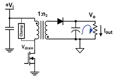
Basic Flyback Converter Circuit
VIC comparison to the SMPS Flyback Converter
| The SMPS Flyback Converter | The VIC |
 |
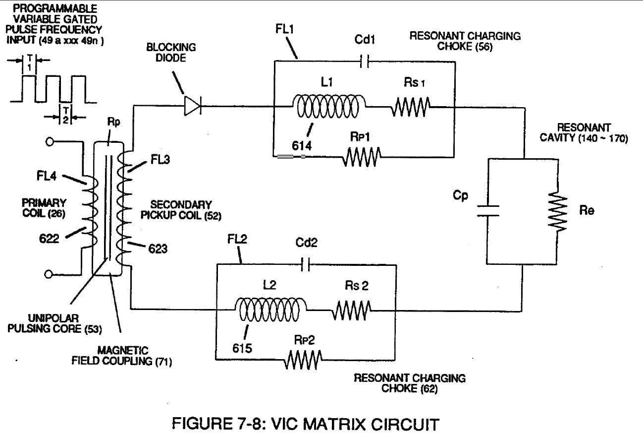 |
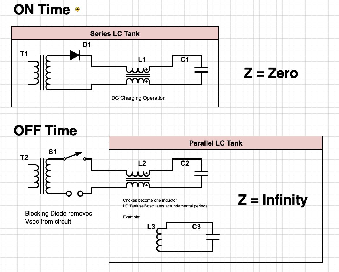
Suggested VIC circuit operation ON vs OFF states.
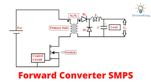
Basic Forward Converter Mode
The VIC compared to a basic Forward Converter
 |
|
LM317 as a Variable Power Supply: 0-35V Adjustable Voltage
7805 and 7812 Voltage Regulators: Building 5V and 12V Power Supplies
 The 7805 and 7812 are popular and reliable voltage regulators used to create stable 5V and 12V outputs, making them ideal for low-power electronics and microcontroller circuits. These voltage regulators are widely used because of their simplicity, efficiency, and capability to provide steady output voltages regardless of input variations. In this article, we will explore how to set up both 7805 and 7812 voltage regulator circuits, as illustrated in Stanley Meyer's schematic, to create regulated 5V and 12V power supplies.
How the 7805 and 7812 Voltage Regulators Work
The 7805 and 7812 are three-terminal voltage regulators that provide fixed output voltages of 5V and 12V respectively. They are capable of handling input voltages between 7V and 35V for the 7805 and 14V and 35V for the 7812. These regulators output stable voltages suitable for powering most small electronic circuits. The three pins on both regulators are:
-
Input (Vin): The input voltage, which needs to be greater than the desired output by at least 2V.
-
Ground (GND): The common ground for both the input and output.
-
Output (Vout): The regulated output voltage, fixed at 5V for the 7805 or 12V for the 7812.
Both regulators have internal current limiting and thermal shutdown features, which make them reliable options for most low-power electronics projects.
Setting Up the 7805 and 7812 as Power Supplies
To create reliable 5V and 12V power supplies, you'll need a few components in addition to the 7805 or 7812 voltage regulators:
-
Step-Down Transformer: A transformer to step down the AC voltage from 110V to around 12V AC for the 7805 or 15V AC for the 7812.
-
Bridge Rectifier (B1): A full-wave bridge rectifier to convert the AC voltage to DC.
-
Filter Capacitors (C1, C2, C3): These capacitors are used to smooth out the DC voltage after rectification, typically 1000μF, 35V capacitors.
-
Input Capacitor (C4, 0.1μF): This capacitor helps stabilize the input voltage to the regulator.
-
Heat Sink (optional): To prevent the regulator from overheating, especially if the current draw is significant.
Here is how to wire the 7805 or 7812 as a regulated power supply:
-
AC to DC Conversion: Start by connecting the step-down transformer (T3) to the 110V AC input to step down the voltage to 12V AC (for 7805) or 15V AC (for 7812). The AC output is then fed to the full-wave bridge rectifier (B1), which converts the AC into DC voltage.
-
Filtering the DC Voltage: Use the filter capacitors (C1, C2, C3), each rated at 1000μF, 35V, to smooth out the DC voltage. These capacitors help reduce the ripple and ensure a steady DC voltage is provided to the voltage regulator.
-
Voltage Regulation: Connect the output from the filter capacitors to the Vin pin of the 7805 or 7812. Add an input capacitor (C4, 0.1μF) between the Vin pin and ground to stabilize the input. The GND pin is connected to the common ground, and the Vout pin provides the regulated 5V (for 7805) or 12V (for 7812) output.
-
Output Filtering: To ensure a stable output, you can add a small capacitor (typically 0.1μF) between the Vout pin and ground. This helps filter out any high-frequency noise.
Practical Considerations
-
Heat Dissipation: When there is a large difference between the input voltage and the regulated output (e.g., 15V input to 12V output), the regulator will dissipate excess energy as heat. To prevent overheating, attach a heat sink to the regulator.
-
Current Capability: Both the 7805 and 7812 can supply up to 1A of current, but this depends on the input voltage and the ability to dissipate heat. If the current requirement is higher, consider using a switching regulator or adding a more efficient cooling solution.
-
Input Voltage: Ensure that the input voltage is at least 2V higher than the desired output. For the 5V output, the input should be at least 7V, and for the 12V output, the input should be at least 14V to maintain proper regulation.
Using the 7805 or 7812 in a Project Box
To create practical 5V or 12V power supplies, you can mount the 7805 or 7812 circuit in a project box. Add an external on/off switch, input and output terminals, and consider adding a fuse on the input for safety. This can provide a versatile power source for your electronics projects.
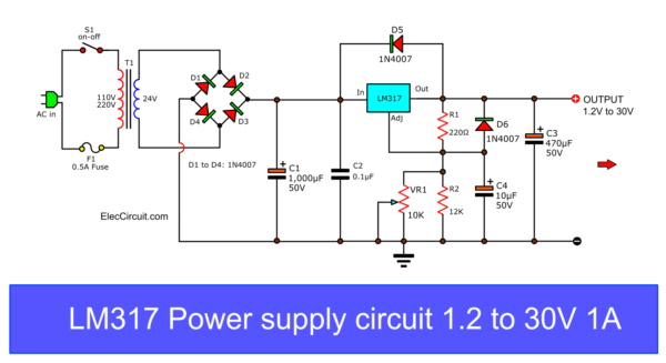
LM317 as a Variable Power Supply
The LM317 is another popular voltage regulator that can be used to create a variable power supply with an adjustable output ranging from 1.25V to 35V. This makes it suitable for projects requiring a flexible voltage source.
To wire the LM317 as a variable power supply, follow these steps:
-
Input Voltage: Connect the input voltage source (e.g., 12V-40V DC) to the Vin pin of the LM317. A 0.1μF capacitor can be added between the input and ground to stabilize the input voltage.
-
Output Voltage: Connect the Vout pin to the positive terminal of your load. Add a 1μF capacitor between the output and ground to improve stability and reduce ripple.
-
Adjust Pin and Voltage Divider: To control the output voltage, connect a 240Ω resistor between the Vout and Adjust pins. Then, connect a potentiometer (typically 5kΩ or 10kΩ) between the Adjust pin and ground. The potentiometer acts as an adjustable resistor that allows you to vary the voltage.
The output voltage (βVoutβ) can be calculated using the following formula:
Vout = 1.25V × (1 + R2 / R1) + Iadj × R2
Where:
-
R1 is the fixed resistor (typically 240Ω).
-
R2 is the resistance of the potentiometer, which varies as you adjust it.
-
Iadj is a small adjustment current (typically ignored for most practical purposes).
Conclusion
The 7805, 7812, and LM317 voltage regulators are easy and reliable solutions for creating regulated power supplies. Whether you need a fixed 5V or 12V output or a variable output using the LM317, these components offer simple setups suitable for a wide range of electronic applications. The addition of heat sinks and careful consideration of input voltages ensure that the regulators operate effectively without overheating. These power supply designs are versatile and can be used to power anything from microcontrollers to sensors, providing stable sources for your DIY electronics projects.
9XD: The 7805/7812 Voltage Regulator Supply
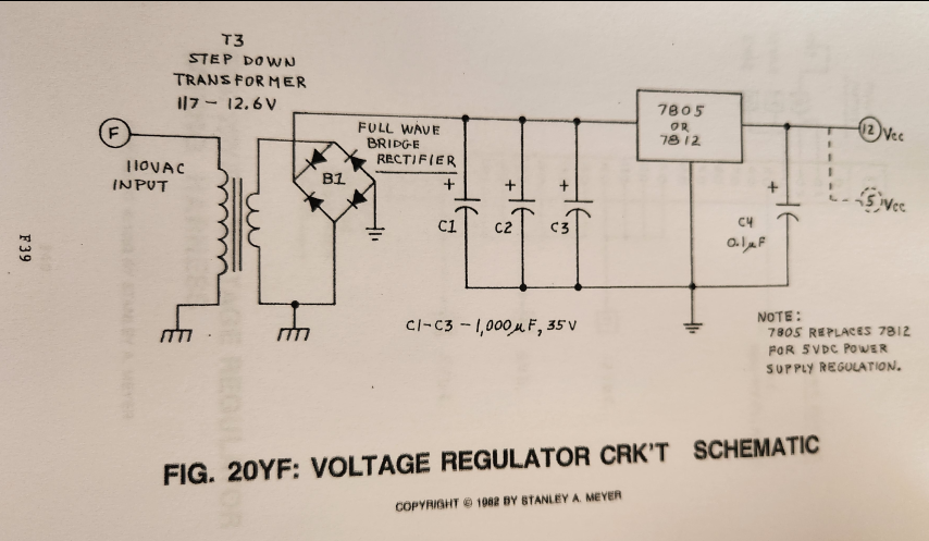
The 7805 and 7812 are popular and reliable voltage regulators used to create stable 5V and 12V outputs, making them ideal for low-power electronics and microcontroller circuits. These voltage regulators are widely used because of their simplicity, efficiency, and capability to provide steady output voltages regardless of input variations. In this article, we will explore how to set up both 7805 and 7812 voltage regulator circuits, as illustrated in Stanley Meyer's schematic, to create regulated 5V and 12V power supplies.
How the 7805 and 7812 Voltage Regulators Work
The 7805 and 7812 are three-terminal voltage regulators that provide fixed output voltages of 5V and 12V respectively. They are capable of handling input voltages between 7V and 35V for the 7805 and 14V and 35V for the 7812. These regulators output stable voltages suitable for powering most small electronic circuits. The three pins on both regulators are:
-
Input (Vin): The input voltage, which needs to be greater than the desired output by at least 2V.
-
Ground (GND): The common ground for both the input and output.
-
Output (Vout): The regulated output voltage, fixed at 5V for the 7805 or 12V for the 7812.
Both regulators have internal current limiting and thermal shutdown features, which make them reliable options for most low-power electronics projects.
Setting Up the 7805 and 7812 as Power Supplies
To create reliable 5V and 12V power supplies, you'll need a few components in addition to the 7805 or 7812 voltage regulators:
-
Step-Down Transformer: A transformer to step down the AC voltage from 110V to around 12V AC for the 7805 or 15V AC for the 7812.
-
Bridge Rectifier (B1): A full-wave bridge rectifier to convert the AC voltage to DC.
-
Filter Capacitors (C1, C2, C3): These capacitors are used to smooth out the DC voltage after rectification, typically 1000μF, 35V capacitors.
-
Input Capacitor (C4, 0.1μF): This capacitor helps stabilize the input voltage to the regulator.
-
Heat Sink (optional): To prevent the regulator from overheating, especially if the current draw is significant.
Here is how to wire the 7805 or 7812 as a regulated power supply:
-
AC to DC Conversion: Start by connecting the step-down transformer (T3) to the 110V AC input to step down the voltage to 12V AC (for 7805) or 15V AC (for 7812). The AC output is then fed to the full-wave bridge rectifier (B1), which converts the AC into DC voltage.
-
Filtering the DC Voltage: Use the filter capacitors (C1, C2, C3), each rated at 1000μF, 35V, to smooth out the DC voltage. These capacitors help reduce the ripple and ensure a steady DC voltage is provided to the voltage regulator.
-
Voltage Regulation: Connect the output from the filter capacitors to the Vin pin of the 7805 or 7812. Add an input capacitor (C4, 0.1μF) between the Vin pin and ground to stabilize the input. The GND pin is connected to the common ground, and the Vout pin provides the regulated 5V (for 7805) or 12V (for 7812) output.
-
Output Filtering: To ensure a stable output, you can add a small capacitor (typically 0.1μF) between the Vout pin and ground. This helps filter out any high-frequency noise.
Practical Considerations
-
Heat Dissipation: When there is a large difference between the input voltage and the regulated output (e.g., 15V input to 12V output), the regulator will dissipate excess energy as heat. To prevent overheating, attach a heat sink to the regulator.
-
Current Capability: Both the 7805 and 7812 can supply up to 1A of current, but this depends on the input voltage and the ability to dissipate heat. If the current requirement is higher, consider using a switching regulator or adding a more efficient cooling solution.
-
Input Voltage: Ensure that the input voltage is at least 2V higher than the desired output. For the 5V output, the input should be at least 7V, and for the 12V output, the input should be at least 14V to maintain proper regulation.
Using the 7805 or 7812 in a Project Box
To create practical 5V or 12V power supplies, you can mount the 7805 or 7812 circuit in a project box. Add an external on/off switch, input and output terminals, and consider adding a fuse on the input for safety. This can provide a versatile power source for your electronics projects.
Conclusion
The 7805 and 7812 voltage regulators are easy and reliable solutions for creating fixed 5V and 12V power supplies. By using a step-down transformer, bridge rectifier, filter capacitors, and the 7805 or 7812 itself, you can build regulated power supplies suitable for a wide range of electronic applications. The addition of heat sinks and careful consideration of the input voltage ensures the regulator operates effectively without overheating. These simple power supply designs can be used to power anything from microcontrollers to sensors, providing stable 5V or 12V sources for your DIY electronics projects.