Rahm & Zeit (Time & Space)
Articles published in both the German and US periodicals from Raum&Zeit (Time & Space) magazines.
- US Edition
- ENERGY of the FUTURE - R&Z - Vol 2 No. 3, 1991
- ENERGY of the FUTURE - R&Z - Vol 2 No. 1, 1990
- ENERGY of the FUTURE - R&Z - Vol 1 No. 6, 1990
- German Edition
US Edition
ENERGY of the FUTURE - R&Z - Vol 2 No. 3, 1991
ENERGY of the FUTURE
WATER FUEL CELL Copyright © 1990 by Stanley A. Meyer - Rahm & Zeit
WFC Hydrogen Gas Management System - Part I
The WFC Hydrogen Gas Management System encompasses many processing patents into a full system-engineering approach to help give a viable answer to the energy problem...by using "Water" as a new Fuel-Source.
The WFC Hydrogen Gas Management (GMS) System not only economically produces "Hydrogen-Fuel" on demand from water but, also, renders Hydrogen-Fuel safer than natural gas allowing existing cars, trucks, or even jets to run on or be powered by Water.
The WFC Hydrogen Gas management (GMS) System is systematically activated and performed in the following way as a retrofit energy-system...defining "Mode of Operability"...on how to use "Water" Fuel.
Related Patents: 4,265,224, 1,213,671, 4,465,455, 4,798,661, 4,826,581, 4,613,304, 1,235,669, 4,275,950 , 1,234,774, 3,970,070 , 1,234,773
WFC Hydrogen Gas Management (GMS) System
Notice Of Technology All rights reserved. Printed in the United States of America. Except in the case of brief quotations embodied in critical articles or review, no part of this WFC tech-brief may be reproduced in any form or by any means, or stored in a databank or retrieval system without express written permission of inventor Stanley A. Meyer. For written approval, fax (614) 871-8075 or send request to 3792 Broadway, Grove City, Ohio 43123.
All graphic illustrations were created and registered under international UCC copyright laws by Stanley A. Meyer.
National Security Laws Patent security is enforced by National Security Laws of each participating country. Do "not" make, sell, or utilize a patented process and/or device without inventor written consent and approval. International patent and copyright laws mandate the same "usage" restrictions.Foreign Grant License Notice: U.S. Government has allowed the WFC technology to go forward into the interna- tional market place by granting foreign grant license No. 492680 issued July 10,1989 and foreign grant license No. 490606 issued Nov. 15, 1989 to Stanley A. Meyer as so specified and required under the Patent Cooperation Treaty (PCT) Act. Both U.S. & Foreign patents laws impose heavy fines & imprisonment on anyone who falsely claims to have participated in the development of any invention. Under the PCT Treaty Act, a declaration of Oath must be signed, certified, and registered prior to the filing of any PCT patent. Add after section titled "National Security Laws."
Illustrations
 |
 |
 |
 |
 |
 |
 |
 |
 |
 |
 |
 |
 |
 |
 |
 |
Water Fuel Cell
(4) which is a component part of Laser Accelerator Assembly (20) of Figure (9kses a GaAs infrared emitting diode (of figure (8) to trigger a SDP8611 Optoschmitt light receiver (2) of Figure (S) from quiescent state (output logic high. B-) (13) to on-state (the mini- mum irradiance that will switch the output low) which switches or triggers the Optoschmitt (2) output to ground state (zero (12). The peak wave- length (3) of Figure (8) being transmit- ted from the infrared emitting diode (ed) (1) to the Optoschmitt receiver (2) is typically (935 nm) and allows the Optoschmitt (2) clock frequency (the speed by which the Optoschmitt changes logic state) to be (100 khz). Optical lens (4) of Figure (9) redirects and focuses the transmitted light source
|
 |
(3) of Figure (8) (traveling infrared light waves) to the Optoschmitt (2) by pass- ing the light source through a series of concentric lenses (40 xxx 4n) of Figure (9) which become progressively smaller from the outer peripheral lens surface (4a) to the inner lens surface (4n). The spatially concentric lenses (4a xox 4n) of Figure (9) causes the beam angle of the light source to trigger the Optoschmitt (2) beyond the minimum irradiance that is needed to switch the Optoschmitt from quiescent state (high logic state/B+) to on-state (output changing to zero volts).
The Derate linearly of light intensity is approximately 125mW/degree C above 25 degree C at a spatial distance of 500 inches between the two infra- red devices (1X2) of Figure (8) as to Figure (9). Transmitted light source (3) is turned-on when an electrical power source of 5 volts is applied to the led () through dropping resister (5) by way of voltage regulator (6) connected to the car electrical system (7). Together, the matched infrared devices (1X2) with optical lens (4) forms optical circuit (8) of Figure (8). Grouping additional opt- cal circuits (8a xxxx 8n) in an in-line or linear arrangement, now, forms Led Pickup Circuit (10) of Figure (8), as shown in Figure assembly (20) of Fig- ure (9).
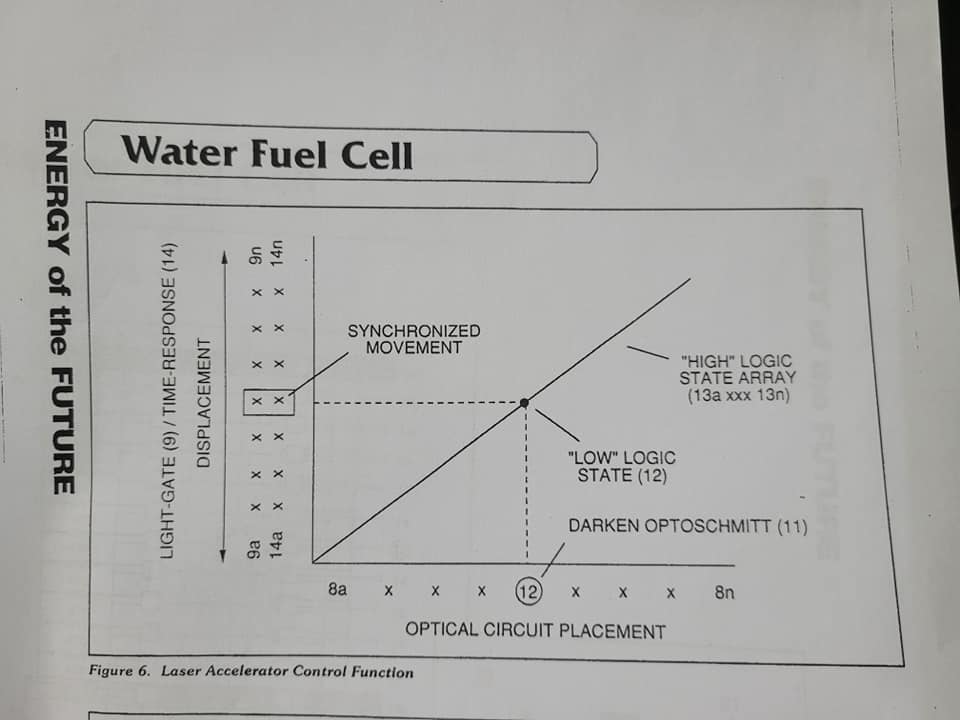
To perform a switch-logic function, light-gate (9) of Figure (8) as to Figure (9) is inserted between the matched infrared devices (1X2) and moved in a linear displacement from one optical circuit (8x) to another optical circuit (8xx), as illustrated in Figure (8)(9) as to Figure (6). Once light-gate (9) blocks and prevents traveling light-bear (3) from reaching the matched Optoschmitt (8xx), the darken Optoschmitt (11) (non-energized) changes output state since the irradiance energy level (3) isreduced to, or below the release point...triggering opposite logic state (12). As light-gate (9) advances to the next optical circuit (8xxx) a new and separate low-state logic function (12) occurs while the previous optical circuit (8xx) reverts back to high-state logic (13). Advancing light-gate (9) still further performs the same opposite (alternate) logic-state switching in a sequential manner until the advancing light-gate (9) reaches the last optical circuit (8) Reversing the movement of light gate (9) performs the same high to low logic witch function but in reverse sequential order. Reversing the direction of the light gate (?) once again reinstates the original sequential switching order, as illustrated in Figure (6) and Figure
Longevity and reliability of component life is typically 100,000 hours since led pickup circuit (10) of figure (8) utilizes no mechanical contacts to perform the sequential logic switch function. Light gate (9) integrated with led pickup circuit (10) make up Laser Accelerator assembly (20), as shown in Figure (9) Light-gate (9) of Figure (9) is mechanically linked to the car acceleration pedal by way of cabling hookup (22)
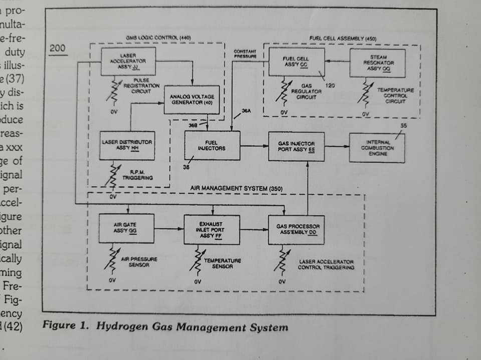
Opposite placement of the matched infrared devices (1)(2) prevents bogus or false triggering of "low" logic state (12) during light-gate displacement (9a xxx 9n) of Figure (6)(7) and (8). If light emitting diodes (led) (la xxxx ln) of figure (8) are electrically disconnected from DC power supply (6), then Led Pickup Circuit (10) outputs are switched to "low" logic state (12a xxxx 12n) which disallows "low" logic state signal (12), resulting in a "shut-down" condition to Hydrogen Gas Control Circuit (200) of Figure (1) Disconnection of power supply (6) to Optoschmitt array (2a ox 2n) of Figure (8) results in a similar "shut down" condition to control cir cult (200), as further shown in Figure (1). This "shut-down" or "Switch-off" condition helps provide a fail-safe operable Fuel Cell (120) of Figure (19) by negating acceleration beyond driver's control.
Acceleration Control Circuit (30)
Moving light gate (9) of figure (8) in direct relationship to the physical placement of optical circuits (8a xxx 8n), sets up a time variable (14a xxx 14n) of Figure (6) from optical circuits (8x) to another optical circuit (8xxx) and/or (8xxxx) or to (8n) since the triggered low logic state (12) of Figure (6) and (7) moves in direct relationship to the displaced light-gate (9), as illustrated in Figure (11). Deflecting (moving) the light-gate (9) to position (8n) takes longer in response-time (14) than deflecting the light-gate to position (8x) and/or (8xx) or (8xxxx). This variable response-time (14axx...12...xx14n) or signal output (15) is now electrically transmitted to Acceleration Control Circuit (30) of Figure 4 since Laser Accelerator Assembly (20) of figure (9) converts mechanical deplacement (9a xx 9n) to electrical time-response (14a xxx 14n) of Figure (6) by linearly moving (forward and/or reverse direction) "low" logic state signal (12) in an array of "high" logic state output signals (13a xxx 13n), as further illustrated in Figure (7) and Figure (11). In some case reverse signal-logic (12axxx...13...xx12n) is applicable by using SDP8601 Optoschmitt which switches logic state from Quiescent static (low" to "high" logic state when de-energized.
Since Led Pickup Circuit (10) of Figure (8) operates up to 100 Khz range or above, electrical sensitivity of Opto-circuit (8) provides an instantaneous response to Driver's acceleration, de-acceleration, or cruise control demands.
As signal output (15) of figure (4) (14 xxxx1214n) is being received by acceleration control circuit (30) of Figure (4) as to Figure (11), circuit (30) converts incoming timeresponse signal (140 x 12 x140) into a vari able time-base unipolar pulse (16), as shown in Figure (7) Circuit (30) electronically and automatically scans out put signal-array (14axxx 12 xx14) (15) until circuit (30) locates, momentarily registers, and translates response- time (14a oxx... 12) into a variable unipolar pulse (17/18) of Figure (7) The sweeping action of the scanning circuit (30) always starts from position (9a) and moves point (8ax) to point (8axxx) of Figure (8)(11) until logic-point (12) is detected. Once logic signal (12) is detected, the sweeping action toggles and recycles back to start position (9a). This toggling (flip back) action elec tronically determines variable time-response (14a xxx) regardless of wherever logic point (12) is being momentarily displaced within circuit array (13a xxx 13n). Toggling action at full-scale deflection (13a xxxx 13n) occurs in the range of (10) Khz or above and thus, allows instant response to Driver's acceleration demands.
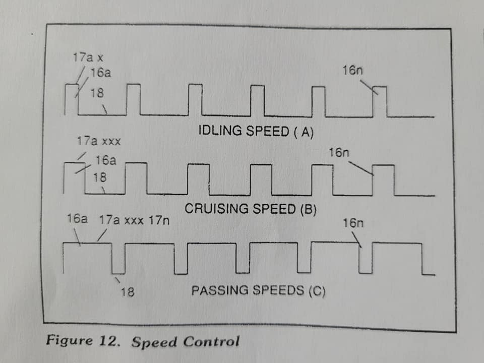
Toggling-time (scanning-time) is directly synchronized to light-gate (9) displacement which, in turn, circuit (30) further sets up and establishes a given pulse shape (16) of Figure (7). Circuit (30) continues to increase pulse width (170) of Figure (7) as the moni- tored (detected by scanning) toggling-time (14a xxxxx.12) Increases when toggle-point (12) moves farther away from start-position (9a) to stop-position (9n), as further shown in Figure 12 as to Figure (11). Pulse width (17a xxx 17n) diminishes when logic-point (12) reverses direction to start position (9a). Finally, circuit (30) reproduces the variable controlled tube-shape (16) in a continuous repetitive manner (16a xxxx 16n) of Fig- ure (12) and electrically transmits the resultant pulse-train signal (19) to Ana- log Voltage Circuit (40), as shown in Figure (4).
In retrospect to engine performance (gas pedal attenuation) (21) of Figure 19), a wider pulse width (17a xxx) of Figure (120) increases (accelerates) engine R.P.M.; whereas, smaller pulse-width (17ax) reduces ide accelerates) engine R.P.M. Cruising speed (128) of Figure (12) is simply accomplished when pulse width re- mains constant
Incoming clock pulse (21a xxx 21n) of Figure (15) originating from Pulse Fre quency Generator (70) of Figure (4) sets up the scan rate (toggling) by which signal input (15) of Figure (4) is elec tronically scanned by circuit (30). The resultant clock pulse (21) of Figure (15) as to Figure (4) is always adjusted to exceed driver's response time to allow for instant acceleration control
Analog Voltage Generator (40)
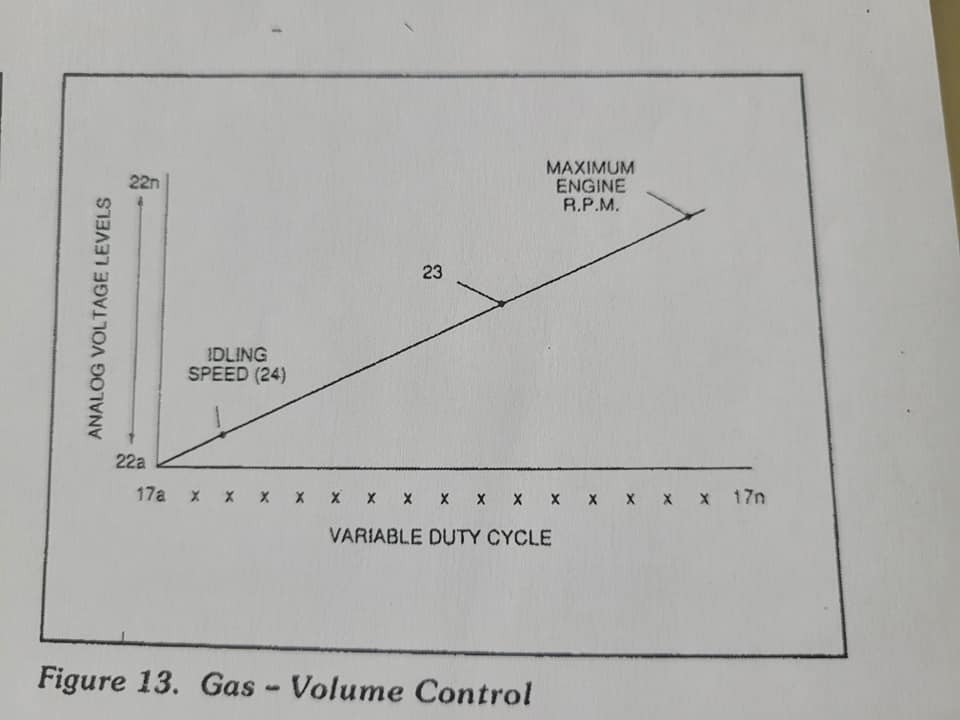
The generated digital signal (19) being electrically transmitted from accelerated control circuit (30) of Figure (4) is, now,electronically detected, translated, and converted into a analog voltage signal (22) which is continuously proportionate to Input signal (19) by ana- log voltage Generator Circuit (40) of Figure (4). The newly formed analog signal (22) of Figure (13) is a voltage level signal that varies continuously in both time and amplitude to produce a voltage level which is directly propor- tional to the physical change in pulse train (16a xxx 16n) of Figure (12). As pulse width (17ax) of signal (19) changes so does analog voltage level output (23) of Figure (13). Widening pulse width to stop-position (17a xxxxx 17n) of Figure (12) causes analog signal (22) to increase to higher voltages levels; whereas, analog voltage level (22) drops (become lower in value) in voltage level when pulse width decreases to start-position (17a). The resultant and varied voltage level (22a xx) varies smoothly over a continuous range of voltage valves (22a xxx 22n) rather than in discrete steps, as illustrated in linear graph (23) of Figure (13).
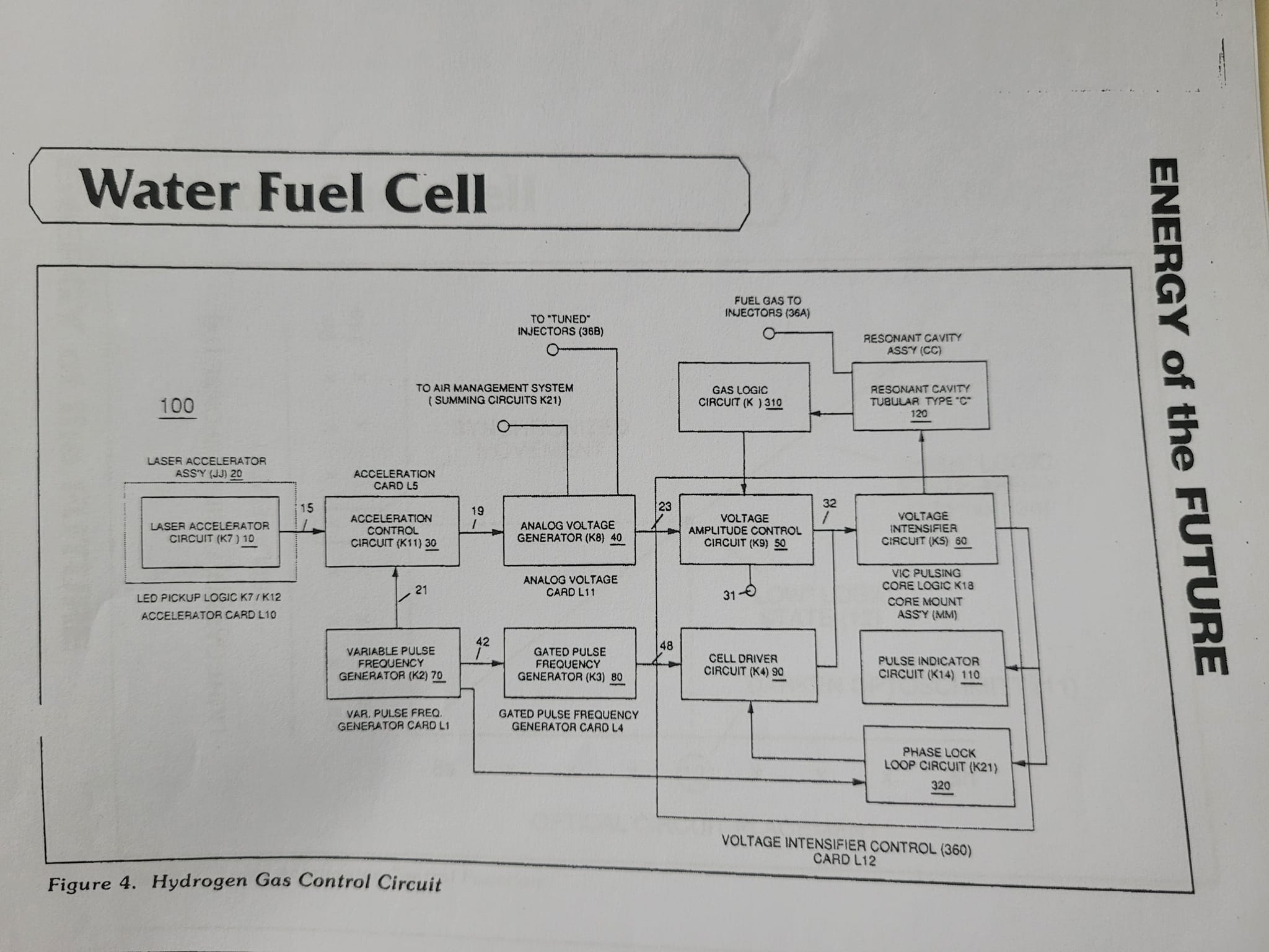
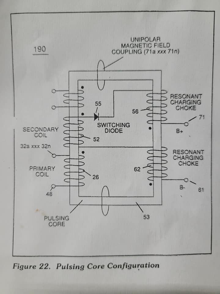
In terms of functionalability and purpose, analog circuit (40) of Figure (4) provides a variable (controlled) voltage output (23) in direct relationship to light-gate (9) displacement which, in turn, sets up and controls Resonant Action (160) of Figure (22) that pro- duces Fuel Gases on demand. Analog circuit (40) also calibrates both engine response). Idling speed (22ax) and maximum en- gine R.P.M. (22a xxx 22n) by adjusting and maintaining a predetermined or given low (24) and high voltage levels respectively, as further illustrated In Figure (13). Voltage valves or levels (22a xxx 22n) simply controls the ap- plied voltage potential across Reso- nant Cavity Assembly (120) of Figure (21) through voltage amplitude control circuit (50) of Figure (4) which is electri cally linked to primary coil (26) of Figure (20) of Voltage Intensifier Cir- cuit (60) of Figure (4).
Voltage Amplitude Control Circuit (50)
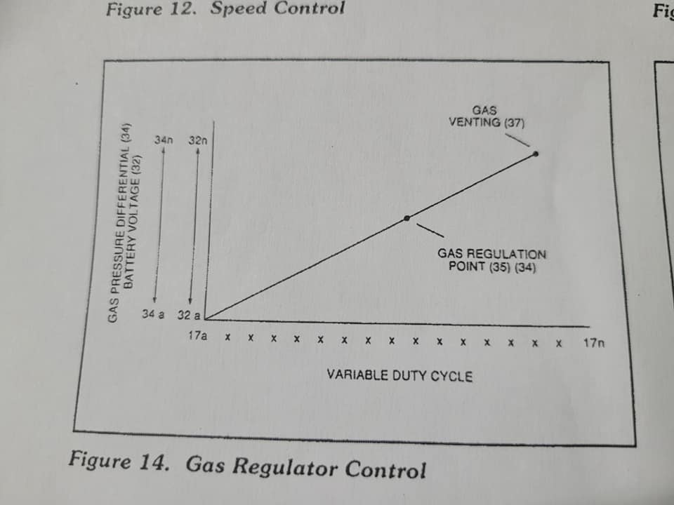
Voltage amplitude control circuit (50) of Figure performs several functions simultaneously. First, regulates car bat tery electrical voltage potential (32) of Figure (14) being applied to primary coll (26) of Figure (20), and secondly, regulates gas pressure of Fuel Cell(120) of Figure (21), as graphically depicted in Figure (14). Each regulatory stage(27) and (28) works separately and independent of each other but are electronically linked or coupled together to produce a common analog signal (32) having a predetermined voltage level (32a xx), as further shown in Figure (14)
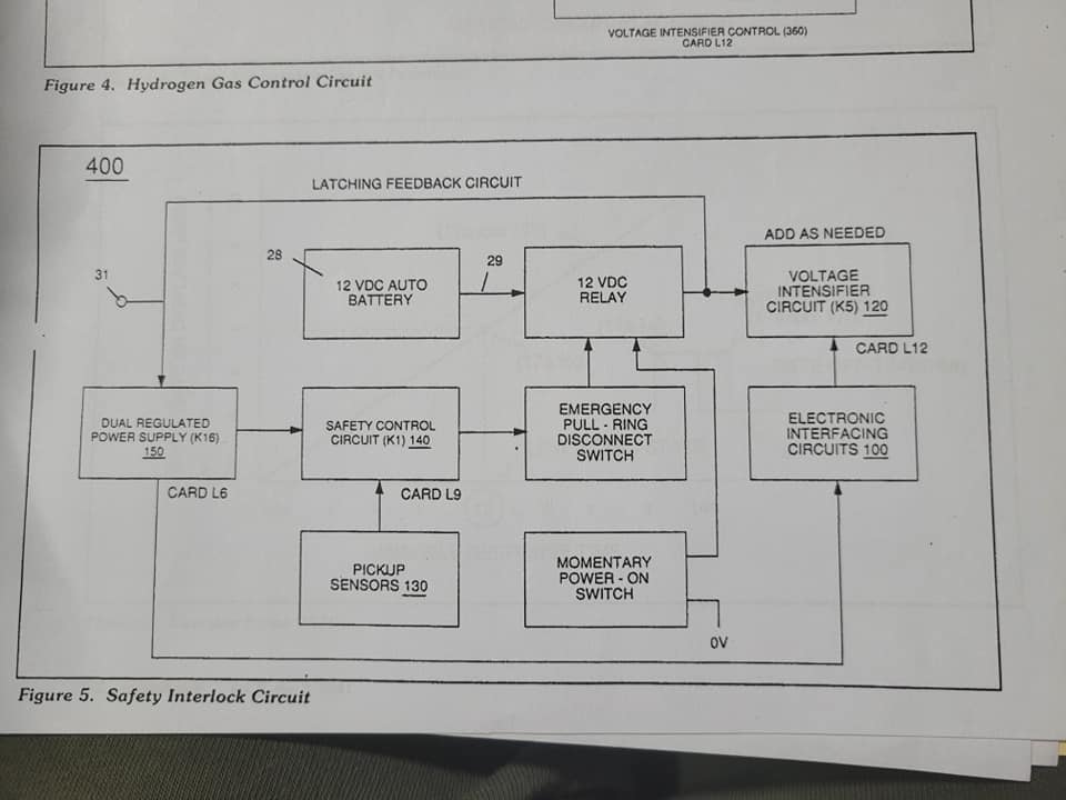
Regulator stage (27) of circuit (50) converts battery voltage potential (29) of Figure (5) via electrical terminal (31) of Figure (4) as to Figure (5) Into an analog voltage signal (32) of Figure (14) which corresponds to but is electrically isolated (crossover voltage from two separate power supplies) from incoming gas volume signal (23) of Figure (13), as shown in Figure (4). Variable voltage range (32a xxx 32n) from one (1) up to twelve (12) volts (regulating battery voltage) is applied across primary coil (26) of Voltage Intensifier Circuit (60) of Figure (20). Second regulator stage (28) simply acts and function as a gas regulator (33) by preventing Fuel Gas production beyond a predetermined gas pressure level (34) of Figure (14) during Fuel Cell operations and, as such, maintains constant gas pressure to Fuel Injectors (36) of Figure () regardless of engine performance (R.P.M.
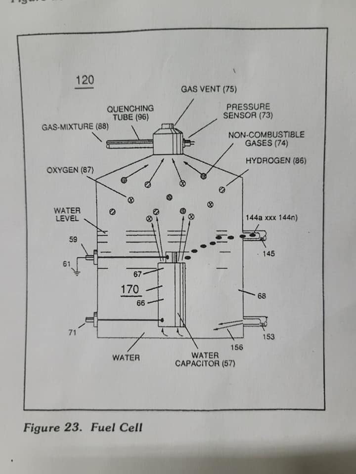
If for example, Fuel Gas production is greater than demand, then, analog signal (32) is reduced to proper voltage level (35) (voltage level directly deter mines gas pressure via Resonant Action) required to maintain gas pressure (34). Conversely, analog signal (32) is always allowed to exceed voltage level (35) during injection (36) of Figure () until gas-point (34) is reached. In cases where linear voltage (32) drops (descending value) below gaspoint (35) then gas regulator stage (28) Increases voltage amplitude (32a xxx 32n) (analog volt- age) to voltage point (35). If gas pres sure (34a xx) should exceed gas point (35) during injector offtime, gas pressure release valve (75) of Figure (23) (gas venting 37 of Figure 14) expels Fuel gases (88) until gas point (34) is either reached or a delay timing circuit activates Safety Control Circuit (14) of Figure (5) which, in ham, switches off or disconnects applied electrical power (28) to Fuel Cell electrical system (400) of Figure (5)
Gas logic circuit (310) of Figure (4) supplies logic function to Voltage amplitude control circuit (50) to maintain proper gas pressure to gas injector (36) of Figure ) by electronically monitoring achieved gas pressure via pressure sensor (73) of Figure (23) In terms of operability, Laser Accelerator Assembly (20) of Figure (4) is, now, attenuating battery voltage potential (32a xxx 32n) which is electrically connected to voltage Intensifier Circuit (60) of Figure (4).
Variable Pulse Frequency Generator (70)
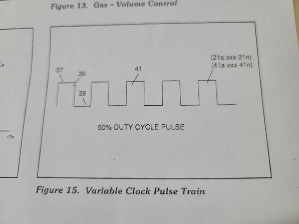
Circuit (70) of Figure (4) is a multi pulse-frequency generator which produces several clock pulses (simultaneously) having different pulse-frequency but maintaining a 50% duty cycle pulse (39) configuration, as illustrated in Figure (15). Pulse on-time (37) and pulse off-time (38) are equally dis- placed to form duty pulse (39) which is duplicated in succession to produce pulse train (41) of Figure (15). Increasing the number of duty pulses (39a xxxx 39n) up to pulse frequency range of 10Khz or above now forms clock signal (21) of Figure (4) which, in tum, per- forms the scanning function of Acceleration Control Circuit (30) of Figure (4) Circuit (70) also produces another Independent and separate clock signal (41a xxx 41n) which is electrically transmitted to and become incoming clock signal (42) for Gated Pulse Frequency Generator Circuit (80) of Fig. ure (4). In both cases, pulse frequency range of each clock signal (21) and (42) can be altered or changed (controlled Independent of each other) to obtain peak performance of Fuel Cell System (100) of Figure (4).
Gated Pulse Frequency Generator (80)
Gated Pulse Circuit (80) of Figure (4) switches "off" and "on" sections of Incoming clock signal (42) to form gated pulse (45) which is, in turn, duplicated in succession to produce gated pulse train (46a xoox 46n) of Figure (16). Together pulse train (44a xxxx 44n) and pulse off-time (43) forms gated pulse duty cycle (45). Pulse train (44a xxx 44n) is exactly the same as pulse train (41a xxxx 41n) and its established pulse frequency (number of pulse cycles per unit of time) changes uniformly when pulse generator (70) of Figure (4) is calibrated and adjusted for system operations.
Newly formed gated duty pulse (45) is proportional to the physical change in pulse train (44 xxx 44n) when circuit (80) is adjusted for calibration purposes. Pulse train (440 xxx 44n) be- comes widen while pulse off-time width (43) becomes smaller, simultaneously Conversely, opposite pulse shaping occurs when circuit (80) of Figure (4) is calibrated in reverse order.
Cell Driver Circuit (90)
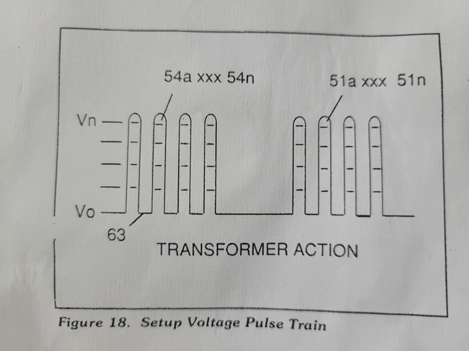
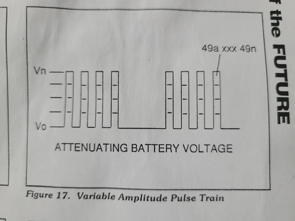
In either case, the resultant or varied pulse train (47a xxx 47n) (calibration of 448 xxx 44n) becomes incoming gated pulse signal (48) of Figure (4) to cell driver circuit (90) of Figure (4) which performs a switching function by switching "off" and "on" electric ground being applied to opposite side (48) of primary coil (26) of Figure (18). The resultant pulse wave form (49a xxxx. 49n) of Figure (17) superimposed onto primary coil (26) is exact duplicate of proportional pulse train (47a xxxx 47n). However, each pulse train (47) (49) are electrically isolated from each other. Only voltage cross-over from regulated power supply (150) of Figure (5) to battery supply (28) occurs, as illustrated in Figure (5).
ENERGY of the FUTURE - R&Z - Vol 2 No. 1, 1990
WATER FUEL CELL Quenching Circuit Technology on how to Render Hydrogen Safer than Natural Gas
by Stanley A. Meyer, 3792 Broadway, Grove City, Ohio 43123
Copyright © 1981 By Stanely A. Meyer
© under UCC 1987 By Stanley A. Meyer
|
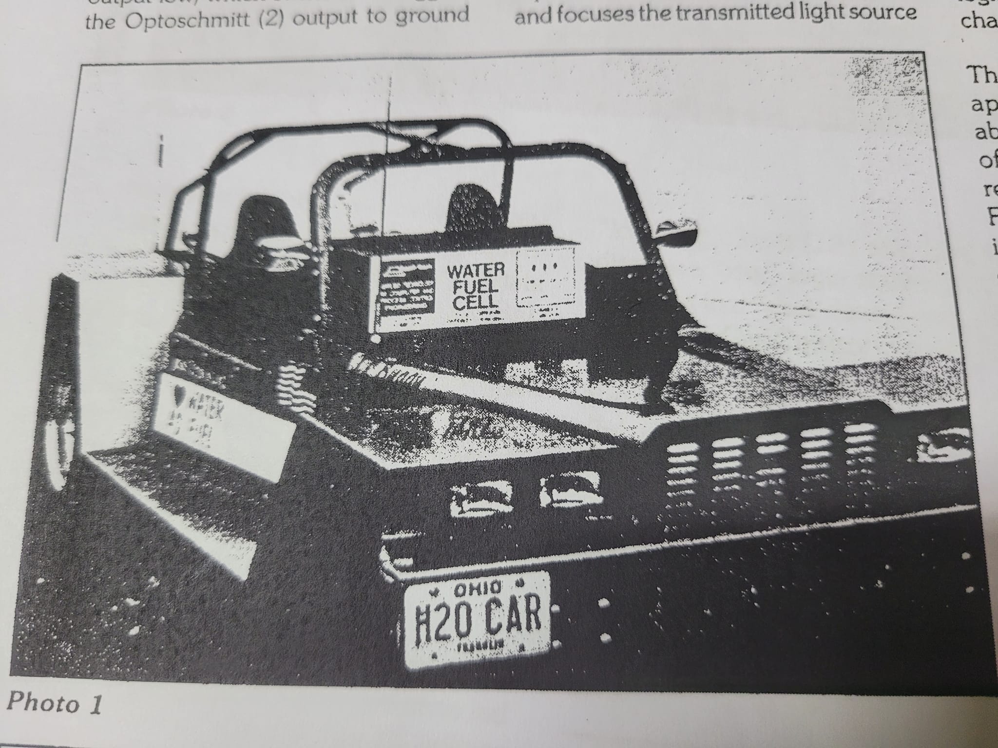
Interview: Cell now ready for existing cars There was an urgency in Stan Meyer's voice, booming into the raum&zeit office on Sept. 7, 1990. Chrystyne Jackson had switched on the intercom and Jeane Manning took notes. "We're finalizing pre-engineering of the (hydrogen-powered) car... to head off the Mideast crisis, Meyer said. If a war starts and chemical weapons are used, he added, oil from the Mideast could be contaminated. Pressure in oil wells internationally is dropping, so even without a war, "we have less than 15 years' supply of oil coming out of the Mideast." The economic base of the world would collapse quickly, if no new source of fuel replaces oil, he added. Therefore a massive international program-similar to the Manhattan Project in level of priority accorded it is needed to develop a hydrogen-based economy. Meyer referred to the Swiss Association for Free Energy conference last year, where he was a guest speaker. When he listened to scientists there talk about alternative energy possibilities, he was shocked. There was apparently no systems engineering approach, other than his water fuel cell. The final patent for his water fuel cell technology - the patent on the electrical polarization process-has now been completed. Pre-engineering is "85 percent finalized", and he planned to run his dune buggy powered by the water fuel cell in the November 1990 solar race in Australia. His technology is to be unveiled to representatives of 176 nations this fall in Sweden. Much information needs to be communicated. Most people think of hydrogen as a volatile fuel. However, Meyer's process "renders hydrogen safer than natural gas". Following is a memo from Stanley A. Meyer (of Grove City, Ohio), describing his Quenching Circuit Technology, He explains that this technology breakthrough allows the water fuel cell technology to be retrofitted to an existing engine without engine change! |
Quenching Circuit TechnologyThe quenching circuit technology is an combination and integration of several Gas-Processes that uses noncombustible gases to render hydrogen safer than natural gas. The "Non-Burnable" gases are used to adjust hydrogen "Burn-Rate" to Fuel- Gas burning levels... recycled to stabilize Gas-Flame temperatures... inter- mixed to sustain and maintain a hydrogen Gas-Flame... and used to prevent Spark-Ignition of supply gases, The utilization and recycling of the non-combustible gases allows the Water Fuel Cell to become a Retrofit Energy System. The Quenching Circuit Technology is systematically activated and performed In the following way. Data Reference: WFC Tech-Brief Method: Using Non Combustible Gases to render Hydrogen safer than Natural Gas Operational ParametersSpark Ignition Tube Spark-Ignition Tube (b) is a tubular test apparatus (1/8 diameter) that deter mines and measures the "Bum-Rate" of different types of Burnable Gases intermixed with Ambient Air, as illustrated in Figure 1.1 |
Water Fuel Cell
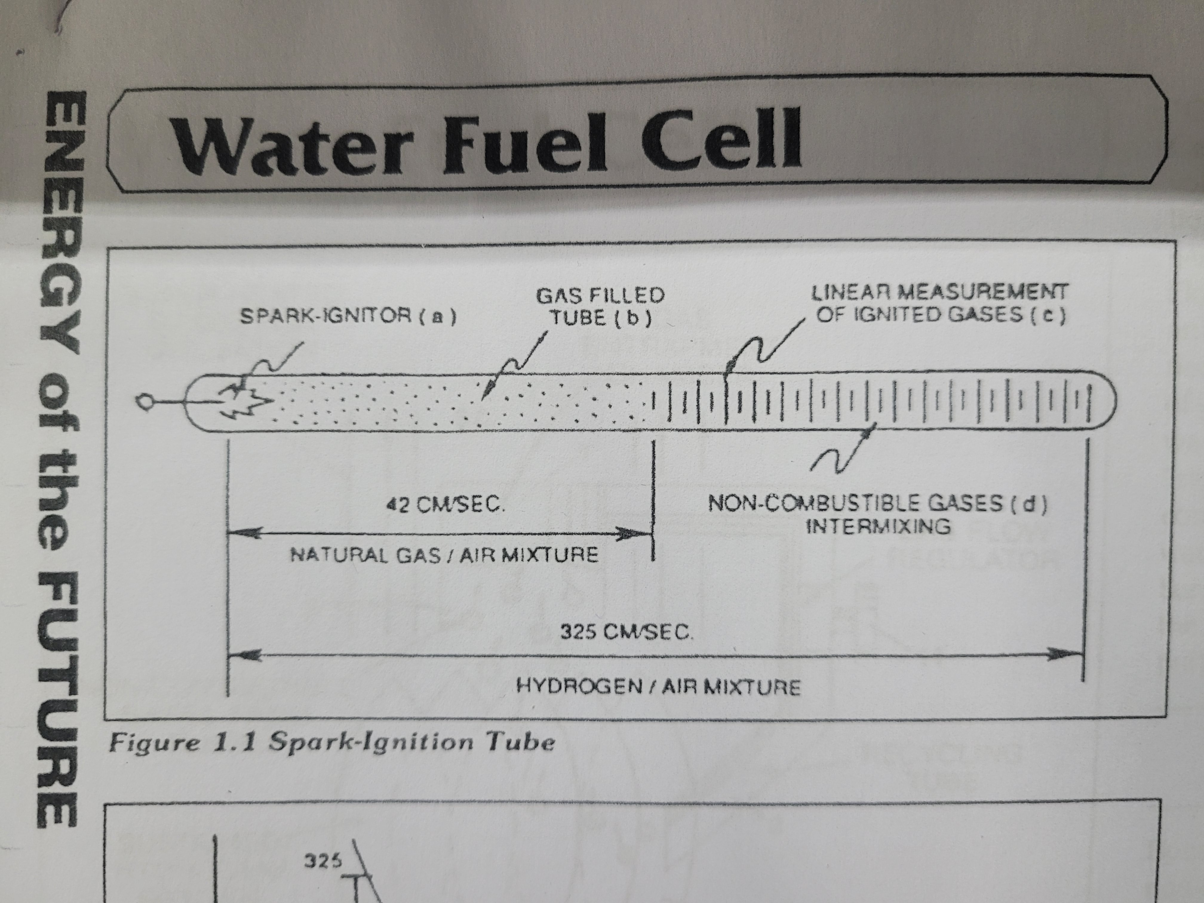 Spark-Ignitor (a) causes and starts the Burnable Gas Mixture (b) to undergo Gas-Ignition which, in turns, supports and allows Gas Combustion to take place...forming and sustaining a Gas- Flame. The expanding and moving Gas-Flame travels (away from spark-ignitor) the linear length of the gas filled tube (c) and is "detected" and "measured (length between spark-ignitor and light-detector) in one second after gas-Ignition, The Gas-Ignition Process, now, establishes the "Burn-Rate" of a Burnable Gas Mixture in centimeters per second (cm/sec.), as illustrated in Figure 23.
Different types of "Burnable" Gas-Mixtures exposed to the Gas-Ignition Process were tested, measured, recorded and systematically arranged as to cm/ sec. length, see vertical bar Graph 23 again The Gas-Ignition Process was performed several times to establish the "average" Burn-Rate of the Fuel- Gases which, in turn, establishes the length of the vertical bars.
Figure 1.1 Spark-Ignition Tube
 Gas Injection Process
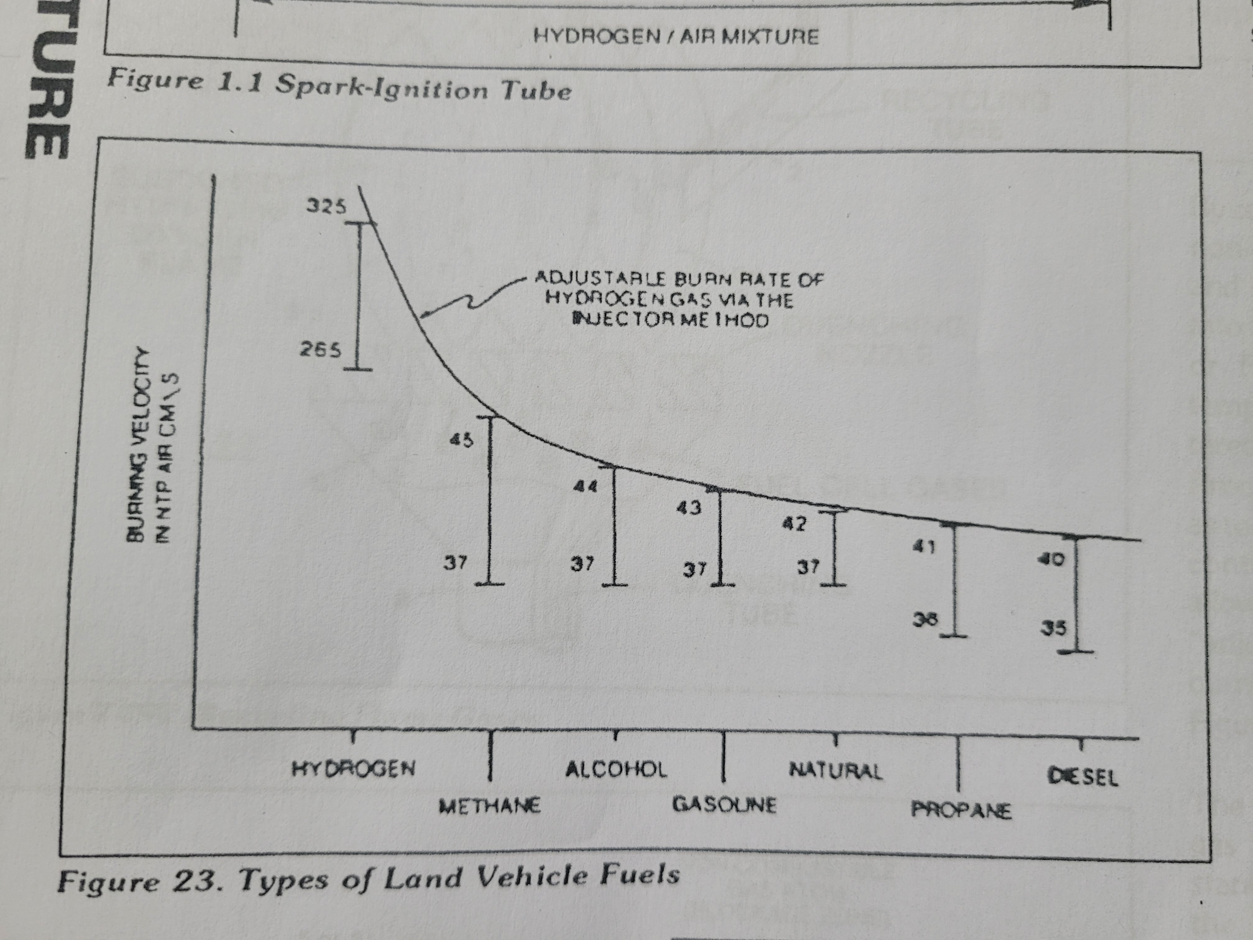
Injecting and Intermixing an Non- Combustible Gas (d) (non-burnable gas) with the "Burnable Gas-Mixture (b) "changes" or "alters" the gas-mixture "Burn-Rate". Increasing the volume-amount of Non-Combustible Gas (d) diminishes and/or lowers the "Bum- Rate" of the Gas Mixture (b/d) still further. Progressive and controlled intermixing of the non-combustible gases (b/d) allowed the "Burn Rate of Hydrogen to be "lowered" or "adjusted" to "match" or "co-equal" the "Burn-Rate" of other Fuel-Gases, see curve line in Figure 23.
Figure 23. Types of Land Vehicle Fuels
In terms of operational performance, the Non-Combustible gas (d) does "Not support the Gas Combustion Process: since the Non Burnable Gas (d) "restricts or "retards the speed at which the Oxygen Atom unites with Hydrogen Atoms to cause Gas Combustion. The "Gas Retarding Process" is, of course, applicable to any type or combination of Burnable Gases or Burnable gas mixture.
Figure 24. Rendering Hydrogen Safer than Natural Gas
 Gas Mixing Regulator
Inherently, the WATER FUEL CELL allows the "Burn-Rate of Hydrogen to be changed" or "adjusted" from 325cm/sec. to 42cm/sec. (Co-equal- ling Natural Gas burning levels) since Non-Combustible Gases (such as Nitrogen, Argon, and other non-burn- able gases) derived from Ambient Air dissolved in natural water performs the Gas Retarding Process... sustaining and maintaining an Open-Air Flame beyond 5,000 degrees F, as illustrated in Figure 24.
Natural water acts and performs as an "Gas Mixing Regulator" when the Fuel Cell is electrically energized by way of voltage stimulation (Electrical Polarization Process) producing an uniform gas-mixture (b/d) regardless of the Gas Flow-Rate of the Fuel-Cell... producing an uniform gas-mixture (b/d) only when needed. In quiescent-state, the supply of gases (b/d) being released from the water bath is "terminated" and "stopped when the Fuel Cell becomes "de-energized".
The unused water, of course, remains as an non- burnable liquid. The gases (b/d) above the water bath is "vented" for safety purposes.
 Flame-Temperature Adjustment
By capturing and recycling the expelled non-combustible gases (d) (derived from and supplied by the water bath) back into the sustained hydrogen gas-flame or Fuel-Cell causes the gas flame temperature to be "changed" or "altered" by way of the Gas Retarding Process, as illustrated in Figure 24SC as to Figure 24. The recycling gases (d) controlled by an Gas Flow Regulator allows the gas flame-temperature to be "adjusted" or "calibrated" to any gas burning level (s), as so illustrated in Figure 23.
The "newly formed and established gas flame-temperature remains constant regardless of the gas flow-rate of the Fuel Cell. Continual feedback of non-combustible gases (d) is, hereinafter, called The Gas Combustion Stabilization Process". Automatically, the Gas Combustion Stabilization Process changes the "Burn-Rate" of the Fuel Cell gases (b/d) when obtaining the desired gas. flame temperature.
Figure 24SD. Preventing Gas Ignition
 Quenching Circuit
Spark-Ignition of the Fuel-Cell gases (b/d) is prevented when the "Gas Retarding Process" is used in conjunction with an "Quenching Circuit", as illustrated in Figure 24, 24SB, 245C, and 24SD.
The non-combustible gases (d) separates and prevents the hydrogen atoms to unite with oxygen atoms to "bring-on" or "initiate" Gas-Ignition. The narrow passaway (at least 1/8 inch long and having an .015 diameter) prevents the moving gas atoms from "Re-Grouping".
The alignment of the Fuel Cell gases (b/d) inside the tubular-passaway is, hereinafter, called "The Quenching Circuit" The Quenching Circuit "Anti- Spark technique" is "Independent" of Gas-Velocity.
Figure 245A. Catalytic Block Asss'y
 Quenching Nozzle
Additional Quenching Circuits arranged In an Disc-shape configuration forms an "Quenching Nozzle" when attached to an "Quenching Tube", as illustrated In Figure 24SC as to Figure 245B, The Multi Gas-Port Disc compensates for increased Gas-Velocity while "preventing" spark-Ignition of the Fuel-Cell gases. The overlapping Flame-Pattern re-ignites the expelling hydrogen gas mixture (b/d) should Flame out occur. Ceramic material is used to form the "Quenching Disc" to "prevent" hale- size enlargement due to gas-oxidation.
The non-combustible gases (d) keeps the Ceramic Material "cool-to-the- touch by projecting the Gas-Flame beyond and away from the disc- surface...the Quenching Disc remains "cool" even if the Gas-Flame Temperature exceeds the melting-point of the disc-material.
 Quenching Tube
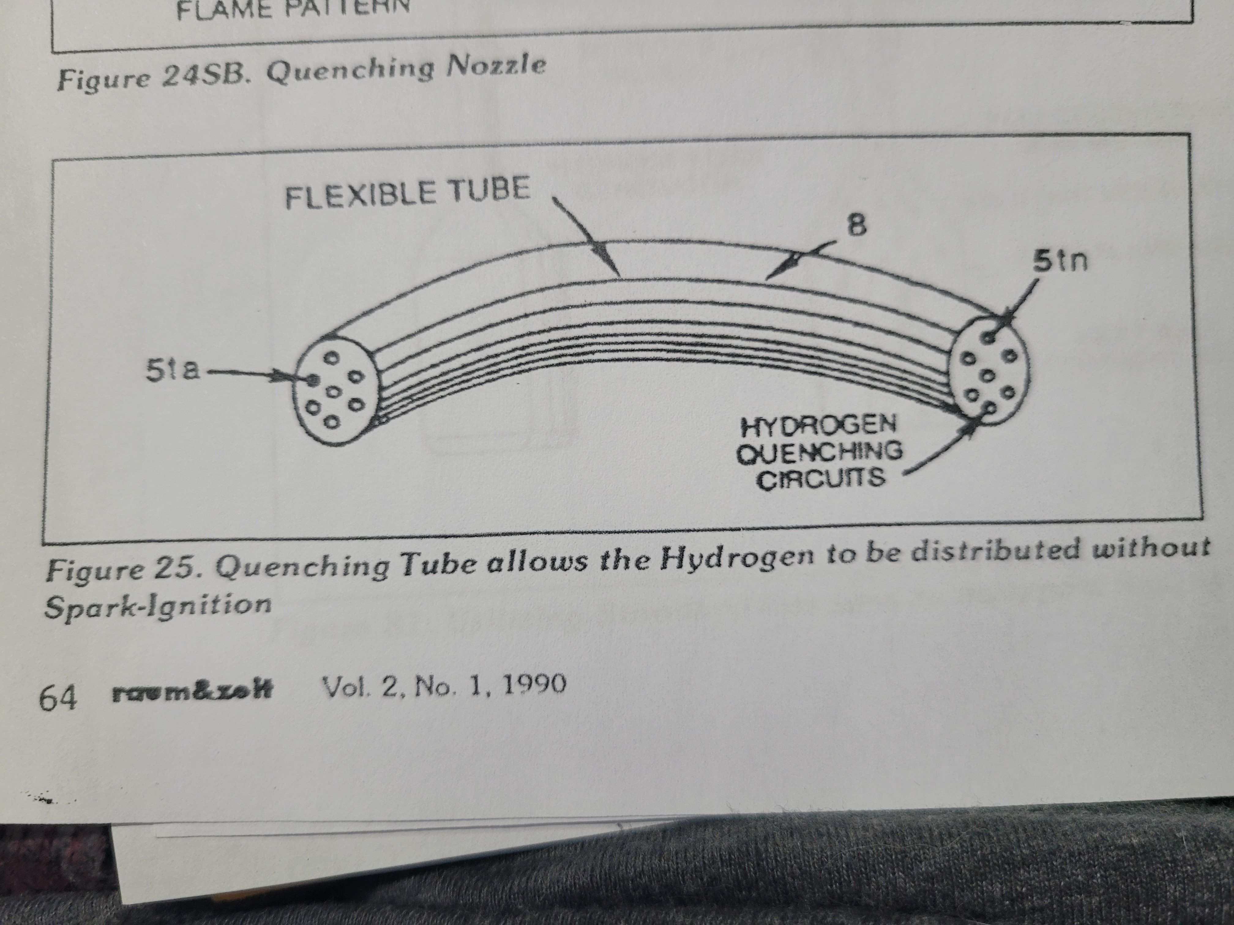
The Quenching Disc is extended into an Flexible Tube to transport the Fuel- Cell gases safely over long distances, as illustrated in Figure 25. The Spark- Arresting Gas-line is, hereinafter, called "The Quenching Tube".
Figure 25. Quenching Tube allows the Hydrogen to be distributed without Spark-Ignition
Catalytic Block Assembly
An inverted hemispherical cavity placed on top of and in space relationship to the "Quenching Disc" insures total gas- combustion by recycling any "escaped" or "unused burnable gases back into the gas-flame for Gas-Ignition... preventing Gas-Oxide formation, as illustrated in Figure 24SA as to Figure 24SC.
Internal Combustion Engine
The Gas Combustion Stabilization Process (recycling non-combustible gases) is also applicable to operating an Internal Combustion Engine without changing Engine Parts since the Gas Retarding Process allows the hydrogen "Burn-Rate" to "equal" the "Burn-Rate" of Gasoline or Diesel-Fuel, as illustrated in Figure 23. The engine pro
Vol 2. No 1, 1990 raum&zelt
ENERGY of the FUTURE - R&Z - Vol 1 No. 6, 1990
Energy of the Future
Raum & Zeit Vol 1. No. 6. 1990
R&Z HFP_Page1.pdf , R&Z HFP_Page10.pdf , R&Z HFP_Page2.pdf , R&Z HFP_Page3.pdf , R&Z HFP_Page5.pdf , R&Z HFP_Page4.pdf , R&Z HFP_Page7.pdf , R&Z HFP_Page6.pdf , R&Z HFP_Page8.pdf , R&Z HFP_Page9.pdf
Hydrogen Fracturing Process
Copyright 1983 in U.S.A. by Stanley A. Meyer under 1987 by Stanley A. Meyer
Over the years man has used water in many ways to make his life on Earth more productive. Why not, now, use water as fuel to power our cars, heat our homes, fly our planes or propel spaceships beyond our galaxy? Biblical prophecy foretells this event. After all, the energy contained in a gallon of water exceeds 2.5 million barrels of oil when equated in terms of atomic energy. Water, of course, is free and abundant. The Hydrogen Fracturing Process dissociates the water molecule by way of voltage stimulation, ionizes the combustible gases by light exposure and, then, prevents the formation of the water molecule during thermal gas ignition...releasing thermal explosive energy beyond "normal" gas burning levels under controlled state.
Circuit Component Interaction:
Pulsing Transformer
The pulsing transformer (a/g) steps up voltage amplitude or voltage potential during pulsing operations. The primary coil is electrically isolated (no electrical connection between primary and secondary coil) to form Voltage Intensifier Circuit (AA). Voltage amplitude or voltage potential is increased when secondary coil (a) is wrapped with more turns of wire. Isolated electrical ground (j) prevents electron flow from input circuit ground.
Blocking Diode
Blocking diode (b) prevents electrical "shorting" to secondary coil (a) during pulse-off time since the diode "only" conducts electrical energy in the direction of the schematic arrow.
LC Circuit
Resonant Charging Choke (c) in series with Excitor-Array (E1/E2) forms an inductor-capacitor circuit (LC) since the Excitor-Array (ER) acts or performs as a capacitor during pulsing operations. The dielectric properties (insulator to the flow of amps) of natural water (dielectric constant being 78.54 @ 25c) between the electrical plates E1/E2) forms the capacitor (ER). Water now becomes part of the VIC in the form of "resistance" between electrical ground and pulse-frequency positive-potential...helping to prevent electron flow within the pulsing circuit (AA) of Figure 1-1.
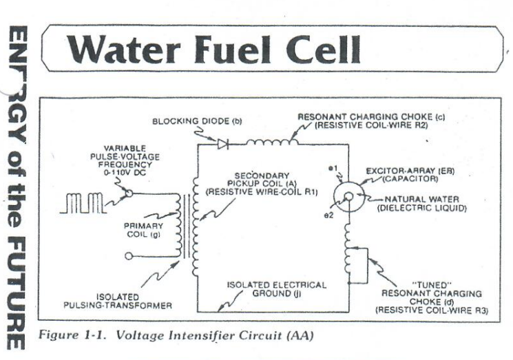
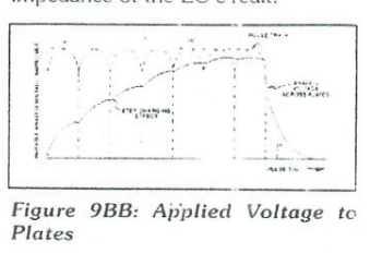
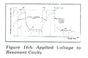
The inductor (c) takes on or becomes a Modulator Inductor which steps up an oscillation of a give charging frequency with the effective capacitance of a pulse-forming network in order to charge the voltage zones (E1/E2) to a higher potential beyond applied voltage input. The inductance (c) and Capacitance (ER) properties of the LC circuit is therefore "tuned" to resonance at a certain frequency. The Resonant Frequency can be raised or lowered by changing the inductance and/or the capacitance values. The established resonant frequency is, of course, independent of voltage amplitude, as illustrated in Figure 9BB as to Figure 16A.
The value of the Inductor (C), the value of the capacitor (ER), and the pulse-frequency of the voltage being applied across the LC circuit determines the impedance of the LC circuit.
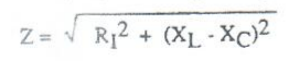
The impedance of an inductor and a capacitor in series, Z is given by:
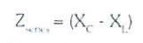
Where:
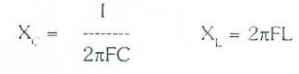
The Resonant Frequency (F) of an LC circuit in series is given by:
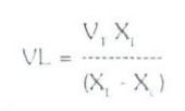
Ohm's law for LC circuit in series is given by:

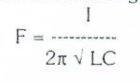
LC Voltage
The voltage across the inductor (c) on capacitor (ER) is greater than the applied voltage (h). At frequency close to resonance, the voltage across the individual components is higher than the applied voltage (h), and, at resonant frequency, the voltage Vt across both the inductor and the capacitor are theoretically infinite. However, physical constraints of components and circuit interaction prevent the voltage from reaching infinity. The voltage (Vl) across the inductor (C) is given by the equation:
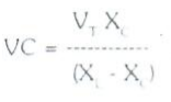
The voltage (Vc) across the capacitor is given by:
During resonant interaction, the incoming unipolar pulse-train (h) of Figure (1-1) as to Figure (9B) produces a step-charging voltage-effect across Excitor-Array (ER), as illustrated in Figure (9BB) and Figure 16A. Voltage intensity increased from zero "ground-state" to a high positive voltage potential in a progressive function. Once the voltage-pulse is terminated or switched-off, voltage potential returns to "ground-state" or near ground-state to start the voltage deflection process over again. Voltage intensity of level across Excitor-Array (ER) can exceed 20,000 volts due to circuit (AA) interaction and is directly related to pulse-train (h) variable amplitude input.
RLC Circuit
Inductor (C) is made of or composed of resistive wire (R2) to further restrict D.C. current flow beyond inductance reaction (XL), and is given by:
Dual Inline RLC Network
Variable inductor-coil (d), similar to inductor (C) connected to opposite polarity voltage zone (E2) further inhibits electron movement or deflection within the VIC. Moveable wiper arm fine "tunes" "Resonant Action" during pulsing operations. Inductor (d) in relationship to inductor (C) electrically balances the opposite voltage electrical potential across voltage zone (E1/E2).
VIC Resistance
Since pickup coil (A) is composed of or made of resistive wire-coil (R1), then total circuit resistance is given by:
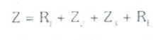
Where, Re, is the dielectric of natural water
Ohm's law as to applied electrical power, which is: E = I*R
Where P = E*I
Electrical power (P) is linear relationship between two variables, voltage (E) and amps (I).
Voltage Dynamic
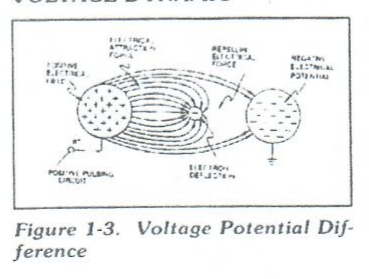
Voltage is "electrical pressure" or "electrical force" within an electrical circuit and is known as "voltage potential". The higher the voltage potential, the greater "electrical attraction force" or "electrical repelling force" is applied to the electrical circuit. Voltage potential is an "unaltered" or "unchanged" energy-state when "electron movement" or "electron deflection" is prevented or restricted within the electrical circuit.
Voltage Performs Work
Unlike voltage charges within an electrical circuit set up an "electrical attraction force" whereas, like electrical charges within the same electrical circuit encourages a "repelling action". In both cases, electrical charge deflection or movement is directly related to applied voltage. These electrical "forces" are known as "voltage fields" and can exhibit either a positive or negative electrical charge.
Likewise, ions or particles within the electrical circuit having unlike electrical charges are attracted to each other. Ions or particles mass having the same or like electrical charges will move away from one another, as illustrated in Figure 1-3.
Furthermore, electrical charged ions or particles can move toward stationary voltage fields of opposite polarity, and, is given by Newton's second law:
A = F / M
Where the acceleration (A) or a particle mass (M) acted on by a net force (F). Net force (F) is the "electron attraction force" between opposite electrically charged entities, and, is given by Coulomb's Law:

Difference of potential between two charges is measured by the work necessary to bring the charges together, and is given by:
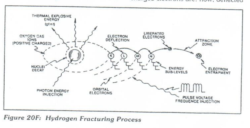
The potential at a point due to a charge (q) at a distance (R) in a medium whose dielectric constant (e).
Atomic Interaction To Voltage Stimulation
Atomic structure of an atom exhibits two types of electrical charged mass-entities, orbital electrons having negative electrical charges (-) and a nucleus composed of electrons and protons having positive charges (+). In stable electrical state, the number of negative electrically charged electrons equal the same number of positive electrically charged protons...forming an atom having "no" net electrical charge.
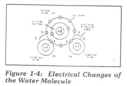
Whenever on or more electrons are "dislodged" from the atom, the atom takes on a net positive electrical charge and is called a positive ion. If an electron combines with a stable or normal atom, the atom has a net negative charge and is called a negative ion. Voltage potential within an electrical circuit (see VIC as to Figure 1-1) can cause one or more electrons to be dislodged from the atom due to opposite polarity attraction between unlike charged entities, as shown in Figure 20F (see Figure 1-3 again as to Figure 1-5) as to Newton's and Coulomb's Laws of electrical force (RR).
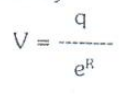
The resultant electrical attraction force (qq') combines or joins unlike atoms together by way of covalent bonding to form molecules of gases, solids, or liquids. When the unlike oxygen atom combines with two hydrogen atoms to form the water molecule by accepting the hydrogen electrons (aa' of Figure 1-4), the oxygen atoms become "net" negative electrically charged (-) since the restructured oxygen atom occupies 10 negative negatively electrically charged electrons as to only 8 positive electrically charged protons. The hydrogen atom with only its positive charged proton remaining and unused, now, takes on a "net" positive electrical charge equal to the electrical intensity of the negative charges of the two electrons (aa') being shared by the oxygen atom...satisfying the law of physics that for every action there is an equal and opposite reaction. The sum total of the two positive charged hydrogen atoms (++) equaling the negative charged oxygen atoms forms a "no" net electrical charge molecule of water. Only the unlike atoms of the water molecule exhibits opposite electrical charges.
Voltage Dissociation of the Water Molecule
Placement of a pulse-voltage potential across the Excitor_Array (ER) while inhibiting or preventing electron from within the VIC (AA) causes the water molecule to separate into its component parts by momentarily, pulling away orbital electrons from the water molecule, as illustrated in Figure 1-5.
The stationary "positive" electrical voltage-field (E1) not only attracts the negative charged oxygen atom but also pulls away negative charged electrons from the water molecule. At the same time, the stationary "negative" electrical voltage field (E2) attracts the positive charged hydrogen atoms. Once the negative electrically charged electrons are dislodged from the water molecule, covalent bonding (sharing electrons) ceases to exist, switching off or disrupting the electrical attraction forces (qq') between the water molecule atoms. Dissociation of the water molecule by way of voltage stimulation is herein called "The Electrical Polarization Process".
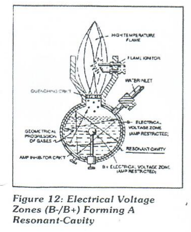
Subjecting or exposing the water molecule to even higher voltage levels causes the liberated atoms to go into a "state" of gas ionization. Each liberated atom taking on its own "net" electrical charge. The ionized atoms along with free floating negative charged electrons are, now, deflected (pulsing electrical voltage fields of opposite polarity) through the Electrical Polarization Process...imparting or superimposing a second physical force (particle-impact_ unto the electrically charged water bath. Oscillation (back and forth movement) of an electrically charged particle by way of voltage deflection is hereinafter called "Resonant Action", as illustrated in Figure 12.
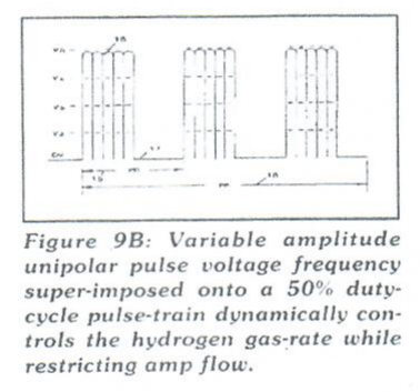
Attenuating and adjusting the "pulse-voltage amplitude" with respect to the "pulse voltage frequency" now, produces hydrogen gas on demand while restricting amp flow.
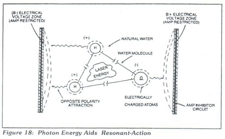
Laster Interaction
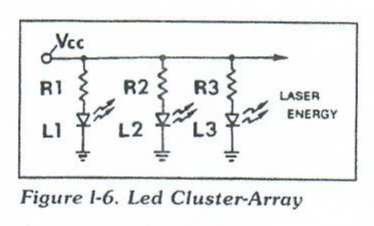
Light Emitting Diodes (LEDs) arranged in a cluster array provides and emits a narrow bank of visible light energy into the voltage stimulated water bath, as illustrated in Figure 19 as to Figure 18. The absorbed laser energy (electromagnetic energy) causes many atoms to lose electrons while highly energizing the liberated combustible gas ions prior to an during thermal gas-ignition. Laser or light is linear with respect to the forward current through the LEDs, and, is determined by
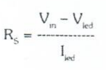
Where I(led) is the specified forward current (typically 20mA, per diode); V(led) is the LED voltage drop (typically 1.7 volts for red emitters). Ohm's Law for LED circuit in parallel array, and, is given by:

Where I is the forward current through LED cluster-array; Vcc is the volts applied (typically 5 volts). Whereby, laser or light intensity is variable as to duty cycle on/off pulse-frequency from 1Hz to 65Hz and above is given by:
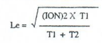
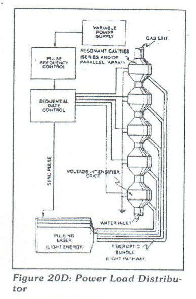
Le is light intensity in watts: T1 is current on time; T2 is current off time; and (ION) = RMS value of load current during on period. Injecting laser energy into the Electrical Polarization Process and controlling the intensity of the light-energy causes the combustible gases to reach a higher energy-state (electromagnetically priming the combustible gas ions) which, in turn, accelerates gas production while raising gas-flame temperatures beyond "normal" gas-burning levels. Injecting "Electromagnetically Primed" and "Electrically Charged" combustible gas ions (from water) into other light-activated Resonant Cavities further promotes gas-yield beyond voltage/laser stimulation, as illustrated in Figure 20D as to Figure 20.
Electron Extraction Process
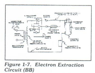
Exposing the displaced and moving combustible gas atoms (exiting water-bath and passing through Gas Resonant Cavity (T), Figure 20JX as to Figure 20H to another or separate pulsing laser energy-source (V) at higher voltage levels (E3/E4) causes more electrons to be "pulled away" or "dislodged" from the gas atoms, as illustrated in Figure 1-8 as to Figure 20F. The absorbed laser energy "forces" or "deflects" the electrons away from the gas atom nucleus during voltage-pulse off time. The recurring positive voltage-pulse (k) attracts (qq') the liberated negative electrically charged electrons to positive voltage zone (E3). While, at the same time, the pulsating negative electrical voltage potential (E4) attracts (qq') the positive electrical charged nucleus. The positive electrical voltage field (E3) and negative electrical voltage field (E4) are triggered SIMULTANEOUSLY during the same duty-pulse. Electron Extraction Circuit (BB) of Figure 1-7 removes, captures, and consumes the "dislodged" electrons (from gas atoms) to cause the gas atoms to go into and reach "Critical State", forming highly energized combustible gas atoms having missing electrons. Resistive values (R4, R6, R7 and dielectric constant of gas Rg) and isolated electrical ground (W) prevents "electron flow" or "electron deflection" from occurring within circuit (BB) during pulsing operations (at resonant frequency) and, therefore, keeps the gas atoms in critical-state by "NOT" allowing electron replacement to occur or take place between the moving gas atoms. The "dislodged" negative charged electrons are "destroyed" or "consumed' in the form of "heat" when Amp Consuming Device (S) (such as a light bulb) is positive electrically energized during alternate pulsing operations. Laser activated or laser primed gas ions repels or "dislodged" electrons being consumed, as illustrated in Figure 20F as to Figure 20G. The Electron Extraction Process (BB) is, hereinafter, called "The Hydrogen Gas Gun" and is placed on top of a Resonant Cavity Assembly, as illustrated in Figure 20JX as to Figure 20H.
Thermal Explosive Energy
Exposing the expelling "laser-primed" and "electrically charged" combustible gas ions (exiting from Gas Resonant Cavity) to a thermal-spark or heat-zone causes thermal gas-ignition, releasing thermal explosive energy (gtnt) beyond the gas-flame stage, as illustrated in Figure 20E as to 20H.
Thermal atomic interaction (gtnt) is caused when the combustible gas ions (from water) fail to unite or form a covalent link up or covalent bond between the water molecule atoms, as illustrated in Figure 1-9.
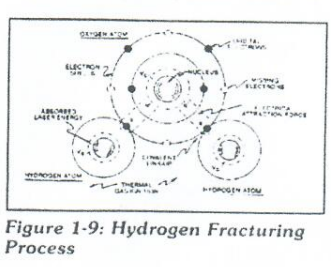
The oxygen atom having less than four covalent electrons (Electron Extraction Process) is unable to reach "stable-state" (six to eight covalent electrons required) when the two hydrogen atoms seek to form the water molecule during thermal gas ignition. The absorbed laser energy (Va, Vb, and Vc) weakens the "electrical bond" between the orbital electrons and the nucleus of the atoms. And, electrical attraction-force (qq'). Being stronger than "normal" due to the lack of covalent electrons, "Locks Onto" and "Keeps" the hydrogen electrons. This Atomic Thermal-Interaction between combustible gas ions is now called "The Hydrogen Fracturing Process". By simply attenuating or varying voltage amplitude in direct relationship to voltage pulse-rate determines Atomic Power-Yield under control-state.
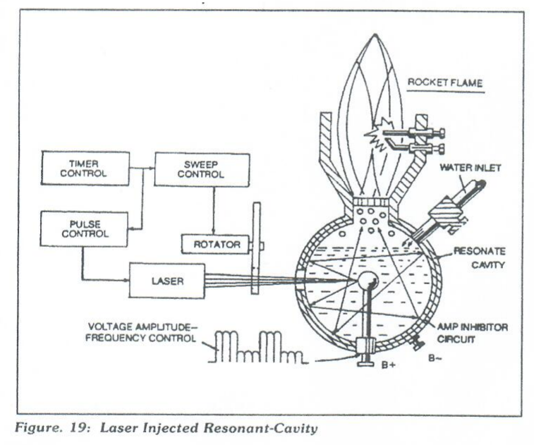
Rocket Propulsion
Add-on resonant cavities (placed beneath the Hydrogen Gas Gun Assembly) arranged in parallel to vertical cluster-array increases the atomic energy-yield of the Hydrogen Fracturing Process undergoing thermal gas-ignition, as illustrated in Figure 17 as to Figure 20. This cluster-assembly or cluster-form is, hereinafter, called "the water power rocket engine".
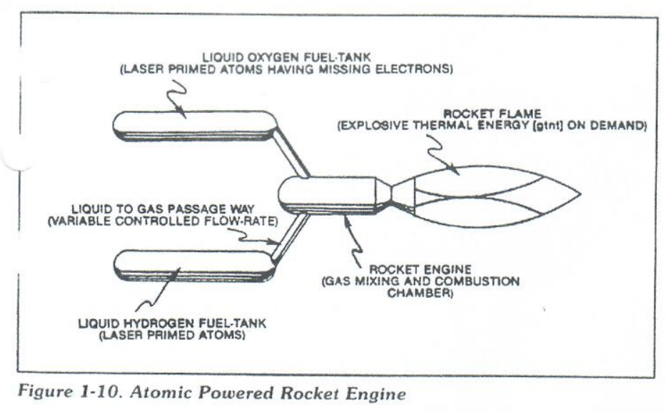
Prolong-rocket-flight carrying heavier payloads is achieved by liquifying the "specially treated" combustible gas ions (laser primed oxygen gas atoms having missing electrons and laser primed hydrogen gas atoms) under pressure in separate fuel tasks affixed to a Rocket Engine, as illustrated in Figure 1-10. Rocket thrust is now, controlled by the flow rate of the combustible ion gases entering the combusting chamber of the rocket engine once gas-ignition occurs.
In Summation
The Hydrogen Fracturing Process simply triggers and releases atomic energy from natural water by allowing highly energized sub-critical combustible gas ions to come together during thermal gas ignition. The Voltage Intensifier Circuit brings on the "Electrical Polarization Process" that switches off the covalent bond of the water molecule without consuming amps. The Extraction Circuit not only decreases the mass size of the combustible gas atoms, but, also and at the same time produces "electrical energy" when the liberated electrons are directed away from the Hydrogen Gas Gun Assembly. The Hydrogen Fracturing Process has the capability of releasing thermal explosive energy up to and beyond 2.5 million barrels of oil per gallon of water under control state...which simply prevents the formation of the water molecule during thermal gas ignition...releasing thermal explosive energy beyond the normal gas combustion process. The Hydrogen Fracturing Process is environmentally safe. The Hydrogen Fracturing Process is design variable to retrofit to any type of energy consuming devise since the Hydrogen Gas Gun can be reduced to the size of an auto spark plug or a gas injector port of a fighter aircraft or enlarged to form a rocket engine. Prototyping determines operational parameters. The Hydrogen Fracturing Process is registered under and certified under the patent cooperation treaty act via foreign grant license #492680 issued July 10, 1989 and foreign grant license #490606 issued Nov. 15, 1988 by the USA as a U.S. patent #4,826,581 issued May 2, 1989. other PCT patent application are pending allowances worldwide.
German Edition
Stan Meyers Wasser-Zellen-Technik
Original source is from Raum Und Zeit magazine, located in Germany.
Raum & Zeit original article: Stan-Meyers-Wasserzellentechnik.pdf
Site Link: Raum-Und-Zeit 1990, Volume #44
New Page
Original article belongs to Raum-Und-Zeit magazine, located in Germany.
Original Article: Stan-Meyer-ermoeglicht-Wasser-als-Brennstoff.pdf
Site Link: Raum-Und-Zeit 1991, Volume #50
New Page
Original article belongs to Raum-Und-Zeit magazine, located in Germany.
Original Article: Wasserzellentechnik-jetzt-fuer-jedes-Auto.pdf
Site Link: Raum-Und-Zeit 1990, Volume #48
New Page
Original Article: SAFE-Kongress-Metaphysik-in-Einsiedeln.pdf
Site Link: Raum-Und-Zeit 1989, Volume #43