**SECTION ONE OVERVIEW:**
[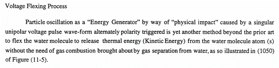](https://stanslegacy.com/uploads/images/gallery/2022-11/vstVa3uq3jjXTc2H-image-1669256512537.png) [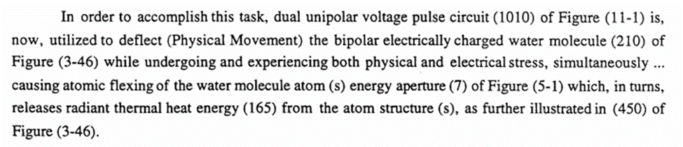](https://stanslegacy.com/uploads/images/gallery/2022-11/F50tJVan945QDzXw-image-1669256519139.png) [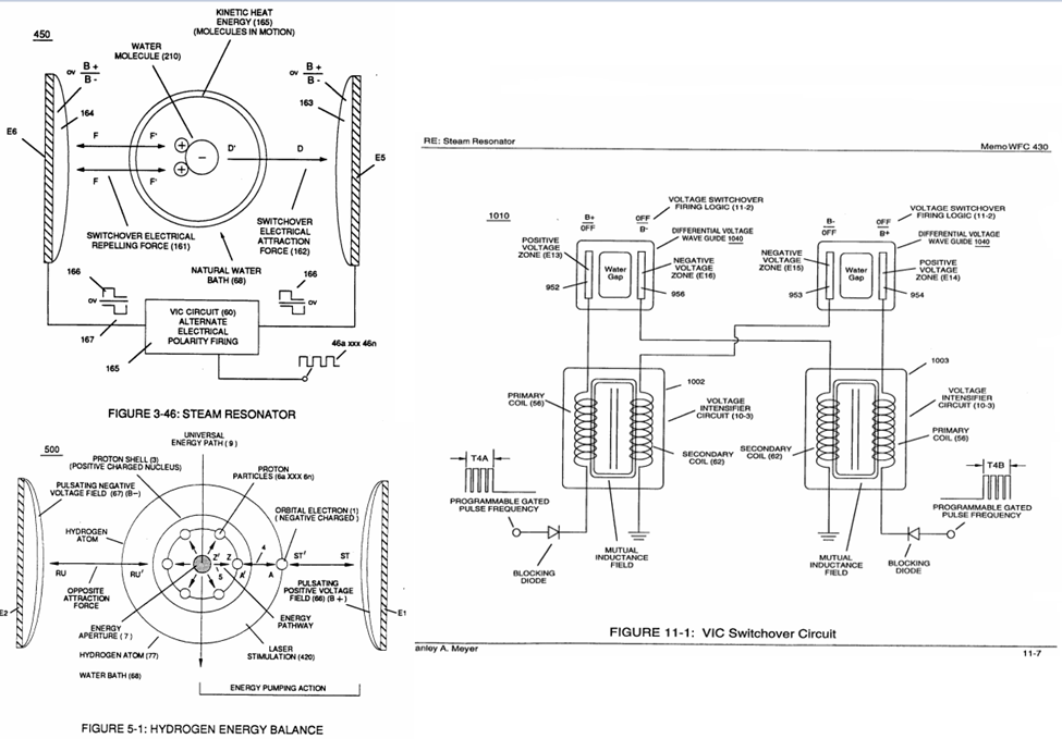](https://stanslegacy.com/uploads/images/gallery/2022-11/NaGMPcaHJ8cKDCWj-image-1669256525795.png)**SECTION ONE NOTES:**
Stan mentions: “a singular unipolar voltage pulse wave-form alternately polarity triggered” is yet another way to release thermal energy from the water molecule. 1. This statement indicates that only one pulse train is utilized, but has electronics that controls the polarity by connection to VIC coil array. The pulse train diagram referenced matches up when superimposed to provide clarity. It appears the T3A/T3B are the transition delay times of the switching between primary coils. [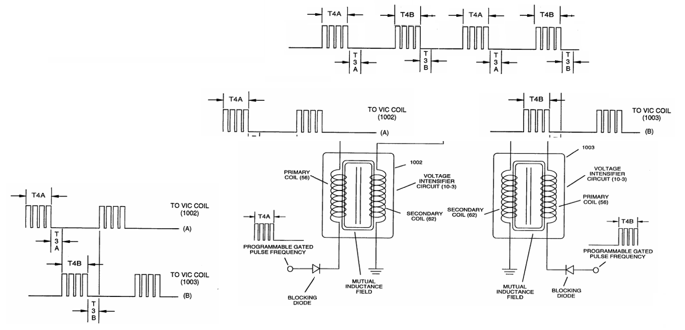](https://stanslegacy.com/uploads/images/gallery/2022-11/2QVkk1Fodiuemdob-image-1669256590714.png) Figure 3-46 shows a setup that indicates bipolar pulse train applied (noticing the voltage is diagrammatically shown in reference to 0v, or ground). This would provide a greater difference of potential, being that the total electric field gradient would be the summation of peak-to-peak voltages. The waveform above could be utilized still. The change being the orientation of VIC primaries, to 180 degrees out of phase with one another, and provide a center tap for 0v.**SECTION TWO OVERVIEW:**
[](https://stanslegacy.com/uploads/images/gallery/2022-11/JfnNkx75FN0xdCUw-image-1669256660670.png) [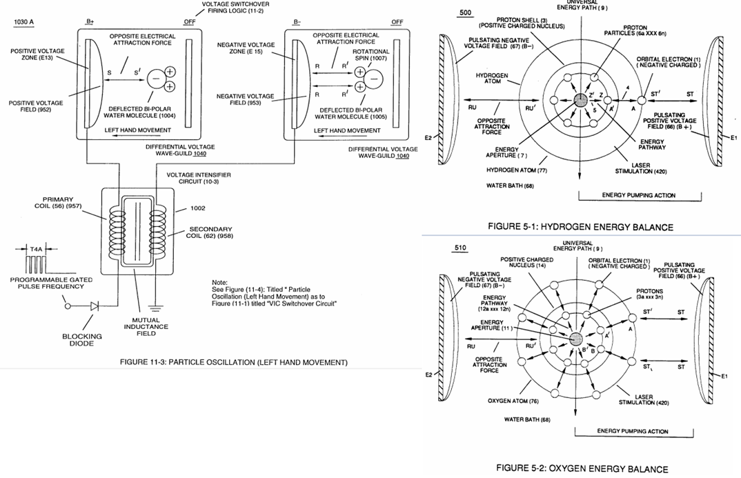](https://stanslegacy.com/uploads/images/gallery/2022-11/4b1RTM5x8hyrHp5F-image-1669256666348.png)**SECTION TWO NOTES:**
Meyers mentions: “causing atomic flexing of the water molecule atom(s) energy aperture (7) of Figure (5-1) which, in turns, releases radiant thermal heat energy (165) from atomic structures. While Meyer doesn’t expressly mention this diagram (Figure 5-10), it is helpful to understand the inter-atomic actions. We can see that “Oscillating Energy Aperture” is designated as (7). This correlation to above excerpt cannot be ignored. Clearly, Meyers is talking about the electrical field causing a flexing or elongation of the atom down to nuclear level. Should also remember that radiant thermal energy is in the form of photons (according to physics). These are the exchange of electromagnetic energy, or heat. Flexing orbital pathways may cause photon emission as electrons are forced to upper/lower energy levels. [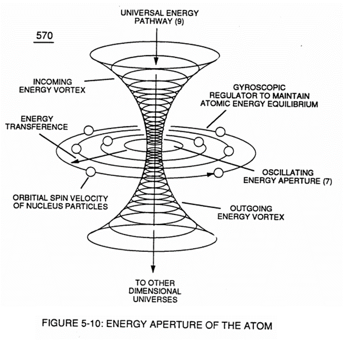](https://stanslegacy.com/uploads/images/gallery/2022-11/HSqAJbS59HNRPtfx-image-1669256692371.png)**SECTION THREE OVERVIEW:**
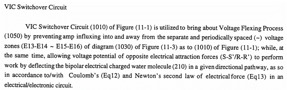
[](https://stanslegacy.com/uploads/images/gallery/2022-11/Aw4eEGyAfXH8dCiA-image-1669256731831.png) [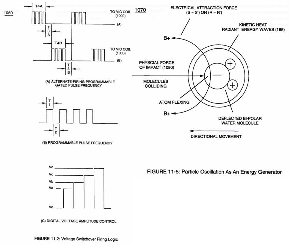](https://stanslegacy.com/uploads/images/gallery/2022-11/ojbYdGdFc5eyNbAV-image-1669256737498.png)**SECTION THREE NOTES:**
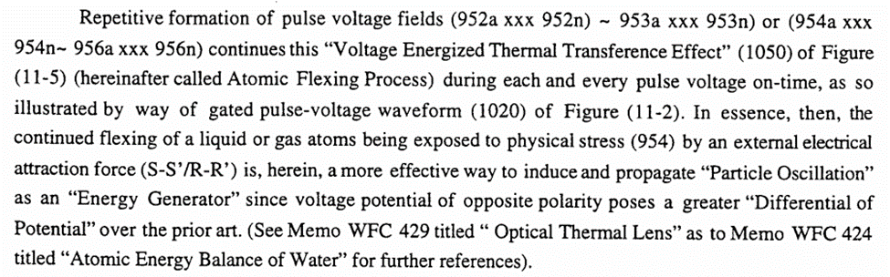
A reference is made here to “1020” of Figure 11-2. There is no such labeling. This indicates that this is an edit of original connotation.
**SECTION FOUR OVERVIEW:**
[](https://stanslegacy.com/uploads/images/gallery/2022-11/Hlvr3ogXJnY67691-image-1669256775342.png) [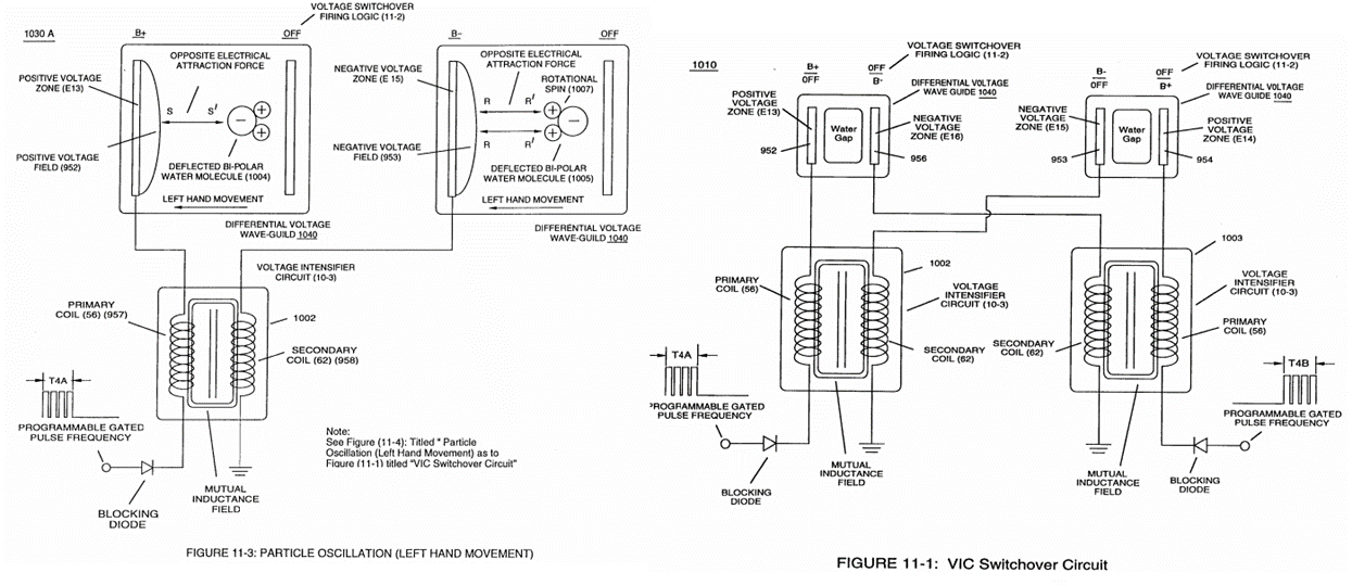](https://stanslegacy.com/uploads/images/gallery/2022-11/SsBhRBxgYQDrrGOD-image-1669256780209.png) [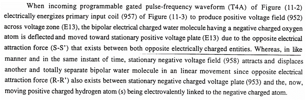](https://stanslegacy.com/uploads/images/gallery/2022-11/FmhlbSE0RjRd6iE8-image-1669256787158.png) [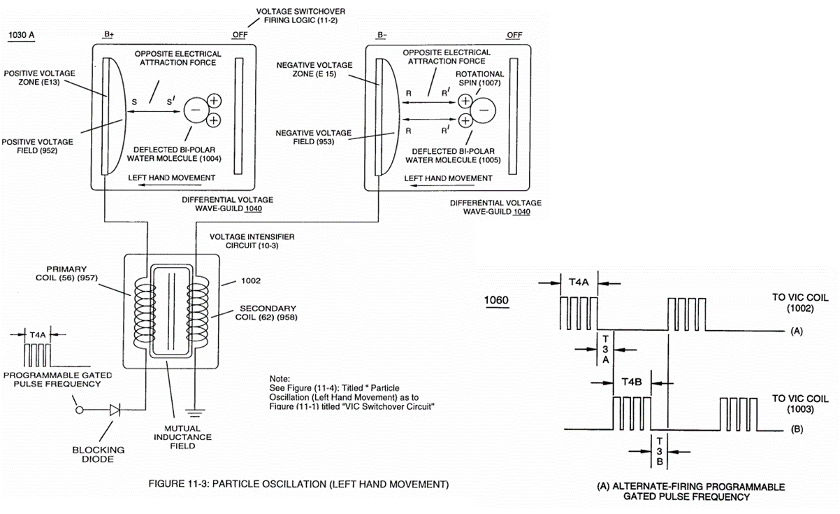](https://stanslegacy.com/uploads/images/gallery/2022-11/ObnwLHyEeF56oznb-image-1669256792636.png) [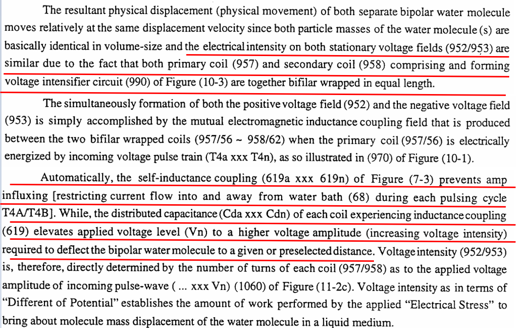](https://stanslegacy.com/uploads/images/gallery/2022-11/fHysf4CNTIqt8fws-image-1669256825897.png) [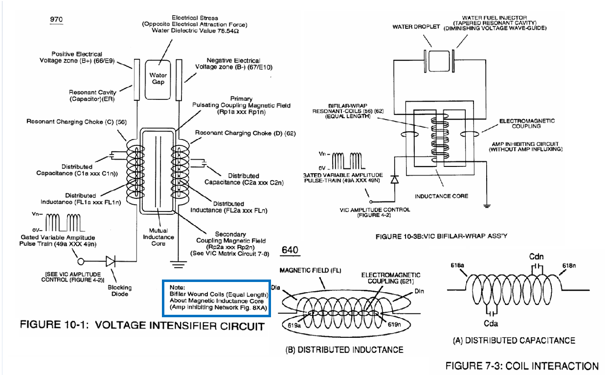](https://stanslegacy.com/uploads/images/gallery/2022-11/NRhGZ4irDJNEQodc-image-1669256841581.png)**SECTION FOUR NOTES:**
[](https://stanslegacy.com/uploads/images/gallery/2022-11/stpubqvxociOvKTH-image-1669256864548.png) Meyers goes on to cover how the amp restriction effect occurs via self-inductance coupling. This in simple terms means as the current rises due to applied potential in the primary coil, its magnetic field starts to grow outward, cutting the adjacent winds next to it. This induces a counter-EMF which acts as a retarding force against the magnetic field that originated (lenz law essentially). The inductance of each coil, divided by its equivalent series ohmic resistance will provide the conventional 5-time constants required to determine maximum current to flow and counter opposing voltage to be overcome which would mean current not longer is in a transient state. This “Choking” effect retards current (electron) movement in a dead short condition without consuming power since energy is stored as a magnetic field. When pulsing/rising current flow is shut off (no later than before 5th time constant) the stored energy within magnetic field rapidly collapses, causing a voltage spike to be generated that is exponentially higher than the source. It must be understood this self-inductive, current retarding effect is the “choking” phenomena Meyer’s references when limiting current in a dead short condition. 50/50 duty cycle pulse train is easier to control this energize/de-energize than a variable duty cycle, since self-inductance causes a RC like curve to form and variable duty cycles would be negatively impacted. Gating allows a certain number of pulses to energize/de-energize/energize….etc to produce this build/collapse effect within a given time period (gate frequency). Meyers then references distribute capacitance being the cause for elevating of the applied voltage level to a higher voltage amplitude. The bifilar geometry of the coils facilitates this. To get an excellent description of this effect, please reference Nikola Tesla’s patent # 512,340. It should be understood that each pair of parallel wrapped wires has a dielectric between them. This is a capacitor by definition. Picture tiny capacitors in series for the number of parallel pairs. Capacitor’s voltage level is increased in a series configuration, while energy storage is reduced proportionately. However, when we connect the termination of coil 1, to the beginning of coil 2 (which is the correct connection method, not the one shown up above), the difference of potential is greatly magnified. This is because 180 degree opposed windings would produce an equivalent peak-to-peak voltage summation for each winding pair, times all the distributed capacitance sections. With this overview, it should be understood that within the inductors, we have a current choking effect, as well as a different of potential (high voltage) storage/source phenomena. The diode is a critical part in producing the step charge also.**SECTION FIVE OVERVIEW:**
[](https://stanslegacy.com/uploads/images/gallery/2022-11/vrbLXwjTMuNYPZ4c-image-1669256902890.png) [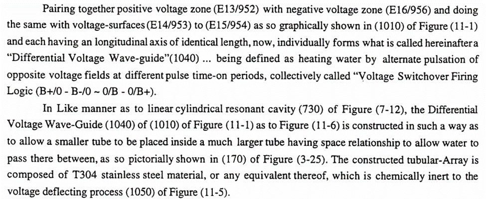](https://stanslegacy.com/uploads/images/gallery/2022-11/fa7X97gPValRynRy-image-1669256908150.png) [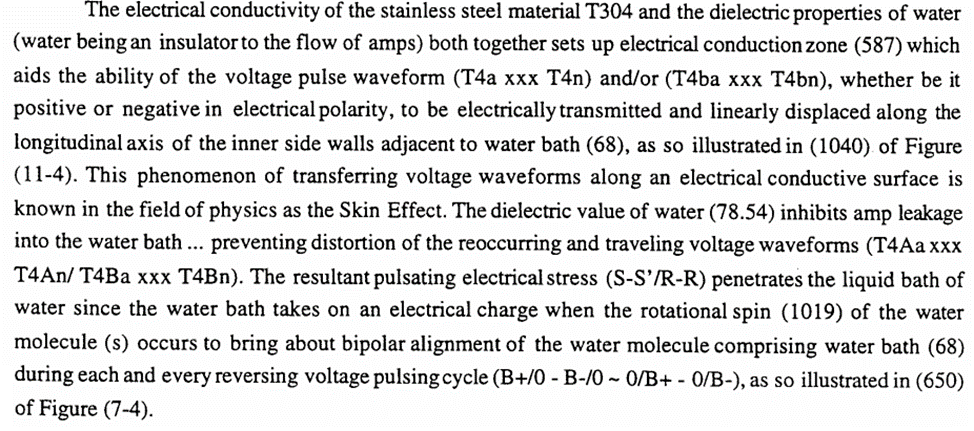](https://stanslegacy.com/uploads/images/gallery/2022-11/H2UMl0e3CIglwkvs-image-1669256914324.png) [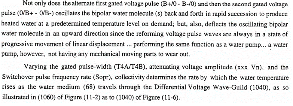](https://stanslegacy.com/uploads/images/gallery/2022-11/pEeBcRuJMpNRZjwf-image-1669256920796.png) [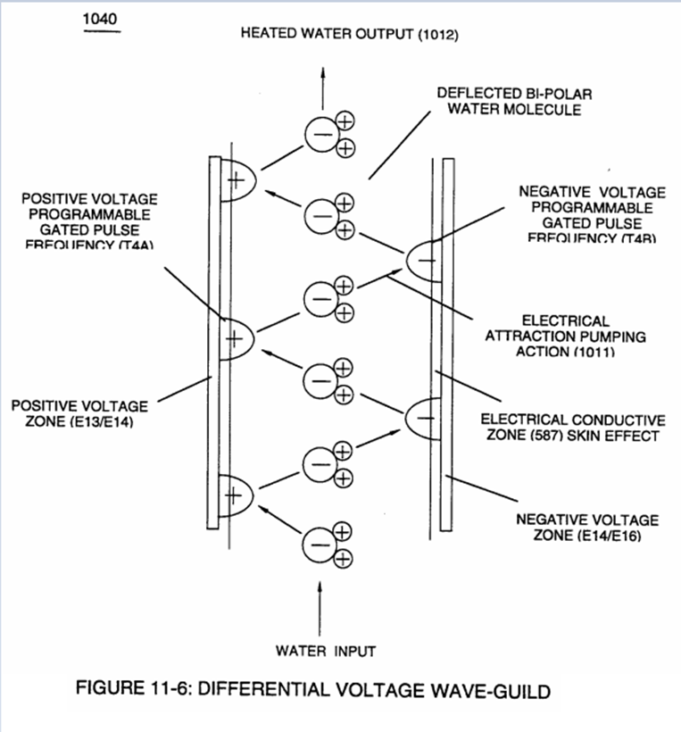](https://stanslegacy.com/uploads/images/gallery/2022-11/PVtsxIhAc3VOwGyT-image-1669256929693.png) [](https://stanslegacy.com/uploads/images/gallery/2022-11/lz089wAIjIjyv52V-image-1669256948369.png) # Steam Resonator - 3D printable replicationAs of 5-3-23 the STLs shown in here are being printed to build a plastic model. At this point, please only consider the following as informational and do not print until all parts are verified to be correct.
[](https://stanslegacy.com/uploads/images/gallery/2023-05/0SBdYEyLocLaZlwo-image-1683164414839.png) ##### **TOP CAP:** Top cap is as the name implies. Screw holes are located around the periphery for mounting inside a water tank. Two holes for electrical connections can be seen near the center. [Steam Resonator Top Cap.stl](https://stanslegacy.com/attachments/135) [](https://stanslegacy.com/uploads/images/gallery/2023-05/hPH6glNoES3WZWq6-image-1683161472325.png) ##### **ORING:** This piece is to be glued to the top cap to accept a sealing O-ring. The STL is for two half pieces that need to be glued together. [](https://stanslegacy.com/uploads/images/gallery/2023-05/b2WpoTfO9qI1q3En-image-1683161501952.png) ##### **S/R MOUNT BASE:** The S/R block is the area that the coaxial orientated electrodes are recession into. This allows electrical connection at the top. [Steam Resonator SR Mount Base.stl](https://stanslegacy.com/attachments/136) [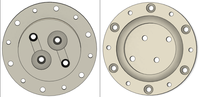](https://stanslegacy.com/uploads/images/gallery/2023-05/NAIIIdmpStmxFHhV-image-1683161258014.png) ##### **OUTER ELECTRODE:** Outer electrode is T-304 stainless steel tube. 0.625" outside diameter. 0.049" wall. 0.527" inside diameter. 7.725" long. Since machining slots could be difficult and costly, a stencil was made (two half pieces for easier printing) that slides over a .625" diameter tube for marking and manual machining. Stencil STLs are listed below. Stencil: [RESONATOR MILLING STENCIL TOP SECTION.stl](https://stanslegacy.com/attachments/140) , [RESONATOR MILLING STENCIL BOTTOM SECTION.stl](https://stanslegacy.com/attachments/139) [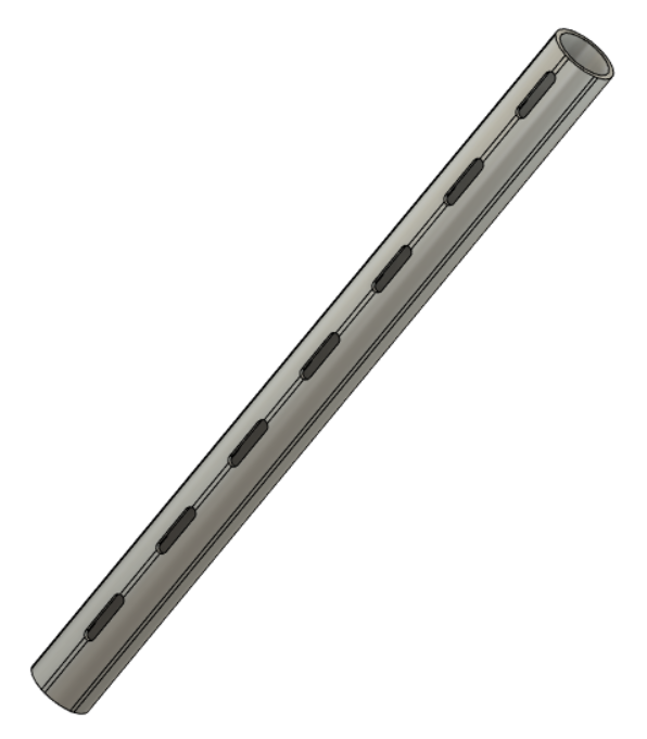](https://stanslegacy.com/uploads/images/gallery/2023-05/fNo2gH6zEnxZ2hBa-image-1683164451008.png) ##### **INNER ELECTRODE:** The inner electrode is T-304 stainless steel material. 0.25" outside diameter. 9.165" long. Machining will need to be done per the drawings. [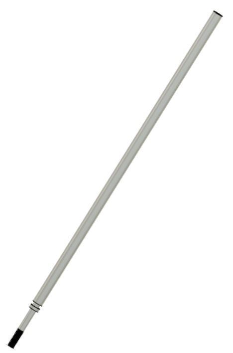](https://stanslegacy.com/uploads/images/gallery/2023-05/my4r1yKBdlpu11Iq-image-1683162046340.png) ##### **INSULATION BLOCK:** The insulative block is an insulation divide between the two outer electrodes. The overall length is 8.125". Square section is .150" tall. Given the length of the whole piece, STLs are half pieces that need glued together. [Insulative block 4.125\_ section .stl](https://stanslegacy.com/attachments/137) [Insulative block 4.00\_ section .stl](https://stanslegacy.com/attachments/138) [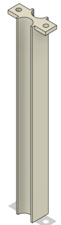](https://stanslegacy.com/uploads/images/gallery/2023-05/Xb8LxsaqLzCIlfHo-image-1683162228195.png) ##### **DELRIN NUT:** Delrin nut goes over the shorter threaded protrusion of the mounting pins through the insulative block [Steam Resonator Delrin Nut .stl](https://stanslegacy.com/attachments/143) ##### **MOUNT PIN:** ##### **END CAPS:** Delrin end caps that have a .300" recession for the inner electrode, and .100" protrusion for inserting into inner diameter of outer electrode. [END CAP REVISED .stl](https://stanslegacy.com/attachments/144) ##### **STEM PLATE:** ##### **ASSEMBLY:** **FIGURE 1:** Place the mounting pins into their respective recessions. The longer threaded portion goes up through the SR block. Shorter threaded ends go downwards through the insulative block's .150" square section. **FIGURE 2:** Insulative block is placed over the mounting pin's protrusions. [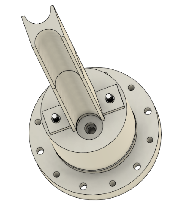](https://stanslegacy.com/uploads/images/gallery/2023-05/8X8RobtRktpMHKiS-image-1683163901973.png) **FIGURE 3:** Outer electrodes, with welded stem plates, are recessed into their corresponding holes (.200" recession into SR block). [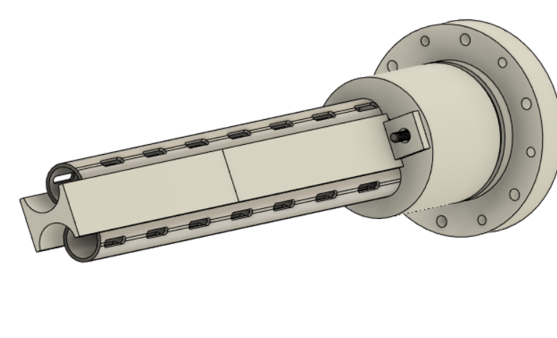](https://stanslegacy.com/uploads/images/gallery/2023-05/5G2DhAC6AZBXijpC-image-1683163947479.png) **FIGURE 4:** Place inner electrodes coaxially inside the outer electrodes. This is accomplished by recessing them into the SR block (.420" recession). [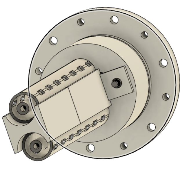](https://stanslegacy.com/uploads/images/gallery/2023-05/b0qugQ2tNqZaV6rc-image-1683164004577.png) **FIGURE 5:** End caps are placed onto the bottom. There is a .100" protrusion on the end caps that goes into the inner diameter of the .625" diameter tube. Through the bottom of these end caps, 6-32 stainless steel screws are secured. [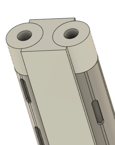](https://stanslegacy.com/uploads/images/gallery/2023-05/tuRdVlvsVfhb9PYp-image-1683163344758.png) **FIGURE 6:** Screw the delrin nuts (.500" outside diameter) onto the mounting pin threaded protrusions to secure the insulative block. [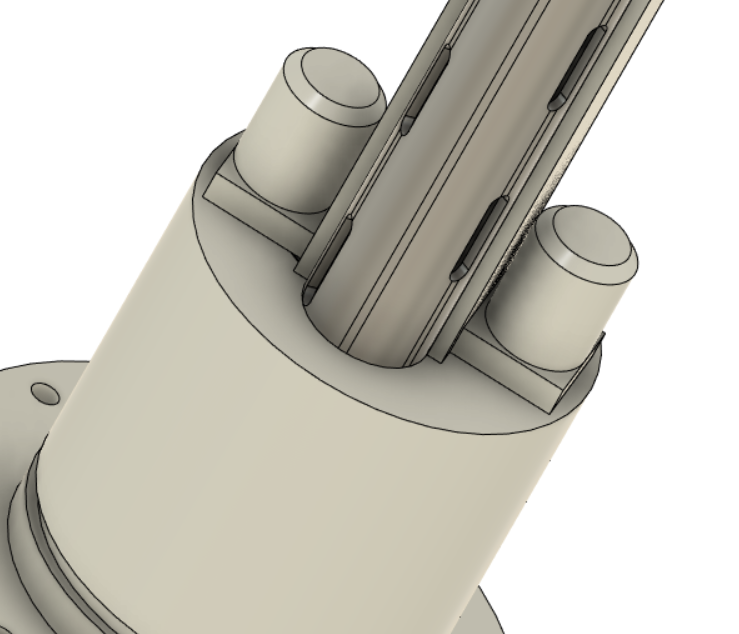](https://stanslegacy.com/uploads/images/gallery/2023-05/z6MvlvBLlrSHwMOW-image-1683164096249.png) **FIGURE 7:** Secure the O-ring support via glue to the underside of the top cover. [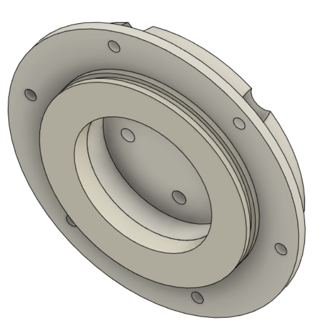](https://stanslegacy.com/uploads/images/gallery/2023-05/0GUEca2QRbiOC1Zr-image-1683164216496.png) **FIGURE 8:** Place top cap onto SR block. [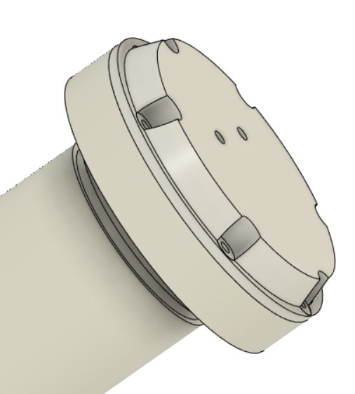](https://stanslegacy.com/uploads/images/gallery/2023-05/T7Rkjk0X3oetSOHJ-image-1683164275593.png) # Steam Resonator - Dimensional Diagrams [Steam Resonator\_Outer Electrode.pdf](https://stanslegacy.com/attachments/213) [Steam Resonator\_SR Block.pdf](https://stanslegacy.com/attachments/214) [Steam Resonator\_Stem Plate.pdf](https://stanslegacy.com/attachments/215) [Steam Resonator\_Top Cap.pdf](https://stanslegacy.com/attachments/216) [Steam Resonator\_Delrin Nut.pdf](https://stanslegacy.com/attachments/217) [Steam Resonator\_Inner Electrode.pdf](https://stanslegacy.com/attachments/218) [Steam Resonator\_End Cap.pdf](https://stanslegacy.com/attachments/219) [Steam Resonator\_Insulator Block.pdf](https://stanslegacy.com/attachments/220) [Steam Resonator\_Mounting Pin.pdf](https://stanslegacy.com/attachments/221) [Steam Resonator\_O Ring.pdf](https://stanslegacy.com/attachments/222) # Steam Resonator Circuitry