WFC 418 - Electrical Particle Generator
- Cover Page
- Electrical Particle Generator
- RE: Electrical Particle Generator
- CIRCUIT COMPONENT INTERACTION
- Figure 9B & 9BB - Applied Voltage To Plates
- LC VOLTAGE
- RLC CIRCUIT
- VOLTAGE DYNAMIC
- Voltage Performs Work
- ATOMIC INTERACTION TO VOLTAGE STIMULATION
- Gas Destabilization Process
- LASER INTERACTION
- Electron Extraction Process
- Magnetic Gas Lattice
- Electromagnetic Enhancement
- Magnetic Field Enhancement
Cover Page
Electrical Particle Generator
How To Use Magnetized Gas To Produce Electrical Energy
On Demand
Water Fuel Cell
(Job 38:22-23)
Jesus Christ is LordInventor:
Stanley A. Meyer
3792 Broadway
Grove City, Ohio 43123
1-614-871-4173
Electrical Particle Generator
Electrical Particle Generator
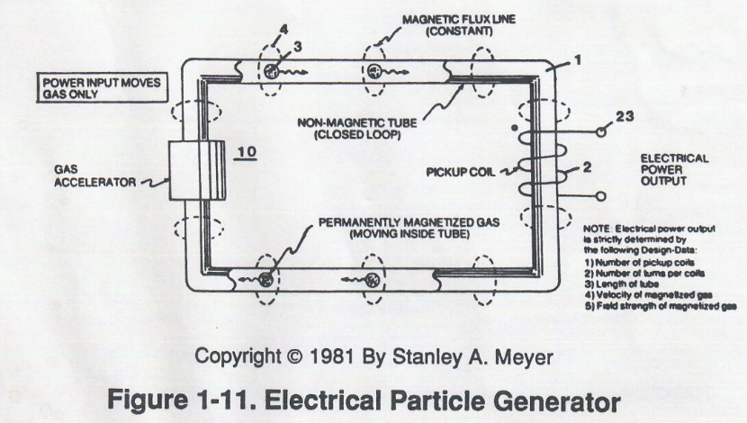
The Electrical Particle Generator capitalizes on and uses a Magnetized Gas to produce Electrical Energy.
Manufacturing the Magnetized Gas required the development and process of taking inert gas atoms and forming a "Stable" Gas-Lattice by way of voltage stimulation called "The Gas Bonding Process."
The "Newly" structured and formed Gas-Lattice is exposed to Laser Energy, which is pulsed to produce a Magnetic Pulse-Wave that traverses pickup windings to generate electricity.
The Gas Bonding Process is systematically activated and performed in the following way.
RE: Electrical Particle Generator
Data Reference: WFC Tech-Brief
Method: How to manufacture, stimulate, and use magnetized gas to produce electrical energy on demand.
 Operational Parameters
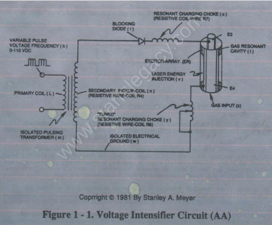
- Primary Coil (L)
- Variable Pulse Voltage Frequency (h) D-110 VDC
- Isolated Pulsing Transformer (m)
- Blocking Diode (f)
- Resonant Charging Choke (c) (Resistive Coil-Wire R7)
- Excitor-Array (ER)
- Secondary Pickup-Coil (n) (Resistive Wire-Coil R4)
- "Tuned" Resonant Charging Choke (y) (Resistive Wire-Coil R6)
- Isolated Electrical Ground (w)
- Laser Energy Injection (v)
- Gas Resonant Cavity (t)
- Gas Input (z)
CIRCUIT COMPONENT INTERACTION
PULSING TRANSFORMER
The pulsing transformer (m) steps up voltage amplitude or voltage potential during pulsing operations.
The primary coil is electrically isolated (no electrical connection between primary and secondary coil) to form Voltage Intensifier Circuit (AA).
Voltage amplitude or voltage potential is increased when secondary coil (n) is wrapped with more turns of wire.
Isolated electrical ground (w) prevents electron flow from input circuit ground.
BLOCKING DIODE
Blocking Diode (f) prevents electrical “shorting” to secondary coil (n) during pulse-off time since the diode “only” conducts electrical energy in the direction of the schematic arrow.
LC CIRCUIT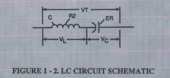 Figure 1-2. LC Circuit Schematic
Resonant Charging Choke (c) in series with Excitor-array (E3/E4) forms an inductor-capacitor circuit (LC) since the Excitor-Array (ER) of Gas Resonant Cavity (t) acts or performs as a capacitor during pulsing operations.
The Dielectric Properties (insulator to the flow of amps) of Argon Gas (dielectric constant being 1.000545 @ 23°C) between the electrical plates (E3/E4) forms the capacitor (ER) of Gas Resonant Cavity (t).
Gas Molecule or Gas atom of Argon (Ar) now becomes part of the Voltage Intensifier Circuit in the form of “resistance” between electrical ground and pulse-frequency positive-potential... helping to prevent electron flow within the pulsing circuit (AA) of Figure 1-1.
The Inductor (c) takes on-or becomes a Modulator Inductor which steps up an oscillation of an given charging frequency when the effective capacitance of an pulse-forming network in order to charge the voltage zones (E3/E4) to an higher potential beyond applied voltage input.
The Inductance (c) and Capacitance (ER of t) properties of the LC circuit is therefore “tuned” to resonate at a certain frequency.
The Resonant frequency can be raised or lowered by changing the inductance and/or the capacitance values.
The established resonant frequency is, of course, independent of voltage amplitude, as illustrated in Figure 9BB.
The value of the Inductor (c), the value of the capacitor (ER of t), and the pulse-frequency of the voltage being applied across the LC circuit determines the impedance of the LC circuit.
Figure 9B & 9BB - Applied Voltage To Plates
|
|
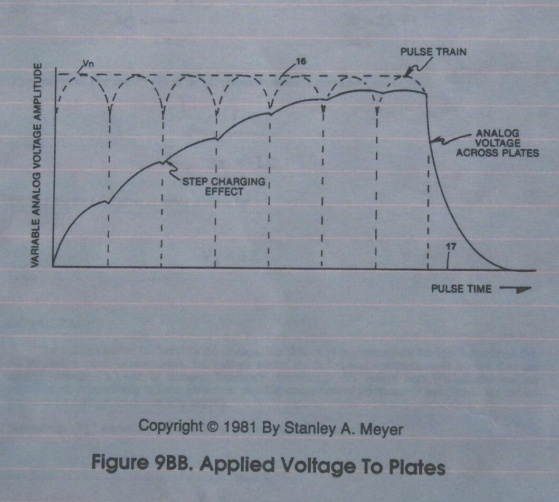 |
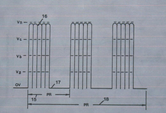
"Figure 9B. Variable Amplitude unipolar-pulse voltage frequency superimposed onto a 50% duty-cycle pulse-train."
LC VOLTAGE
The impedance of an inductor and a capacitor in series, Zseries, is given by
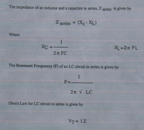
Zseries = (Xc−Xl)
Where
Xc = 1 / 2(pi)FC
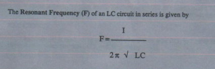
The Resonant Frequency (F) of an LC circuit in series is given by
Ohm’s Law for an LC circuit in series is given by
Vt = IZ
LC VOLTAGE
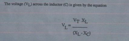
The voltage across the inductor (c) or capacitor (ER of t) is greater than the applied voltage (h).
At frequency close to resonance, the voltage across the individual components is higher than the applied voltage (h), and, at resonant frequency, the voltage VT across both the inductor and the capacitor are theoretically infinite.
However, physical constraints of components and circuit interaction prevent the voltage from reaching infinity.
The voltage (VL) across the inductor (C) is given by the equation:
RLC CIRCUIT
The voltage (VC) across the capacitor is given by:
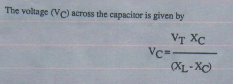
During resonant interaction, the incoming unipolar pulse-train (h) of Figure (1-1) as to Figure (9B) produces an step-charging voltage-effect across Excitor-Array (ER of t), as illustrated in Figure progressive function.
 Figure 1-1 Figure 1-1 |
Figure 9B |
Once the voltage-pulse is terminated or shut-off, voltage potential returns to an "ground-state" or near ground-state to start the voltage deflection process over again.
Voltage intensity or level across Excitor-Array (ER of t) can exceed 20,000 volts due to circuit (AA) interaction and is directly related to pulse-train (h) variable amplitude input.
RLC CIRCUIT
Inductor (c) is made of or composed of resistive wire (R7) to further restrict D.C. current flow beyond inductance reaction (XL), and is given by

Dual-inline RLC NETWORK
Variable inductor-coil (y), similar to inductor (c) connected to opposite polarity voltage zone (E4) further inhibits electron movement or deflection within the Voltage Intensifier Circuit.
Moveable wiper arm fine “tunes” "Resonant Action" during pulsing operations.
Inductor (y) in relationship to inductor (c) electrically balances the opposite voltage electrical potential across voltage zones (E3/E4).
VIC RESISTANCE
Since pickup coil (n) is also composed of or made of resistive wire-coil (R4), then, total circuit resistance is given by
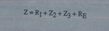
Where, RE is the dielectric constant of Argon (Ar).
VOLTAGE DYNAMIC
Electrical power (P) is a linear relationship between two variables, voltage (E) and Amps (I).
 VOLTAGE DYNAMIC
- Positive Electrical Field
- Electrical Attraction Force
- Electron Deflection
- Repelling Electrical Force
- Negative Electrical Potential
- Positive Pulsing Circuit
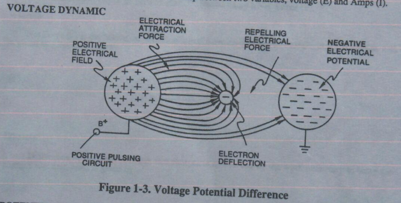
Figure 1-3. Voltage Potential Difference
POTENTIAL ENERGY
Voltage is “electrical pressure” or “electrical force” within an electrical circuit and is known as “voltage potential.”
The higher the voltage potential, the greater the force or electrical repelling force is applied to the electrical circuit.
Voltage potential is an unaltered or unchanged energy-state when “electron movement” or “electron deflection” is prevented or restricted within the electrical circuit.
Voltage Performs Work
Unlike voltage charges within an electrical circuit set up an “electrical attraction force”; in both cases, electrical charges within the same electrical circuit generates an repelling action.
Electrical forces are known as “voltage fields” and can exhibit either a positive or negative electrical charge.
Likewise, Ions or Particles within the electrical circuit having unlike electrical charges are attracted to each other. Ions or particles mass having the same or like electrical charges will move away from one another, as illustrated in Figure 1-3.
Furthermore, electrical charged ions or particles can move toward stationary voltage fields of opposite polarity, and, is given by Newton's second law
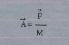
Where
The acceleration (A⃗) of an particle mass (M) acted on by a Net Force (F⃗).
Whereby
Net Force (F⃗) is the “electrical attraction force” between opposite electrically charged entities, and, is given by Coulomb’s Law
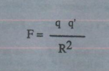
Whereas
Difference of potential between two charges is measured by the work necessary to bring the charges together, and, is given by
The potential at a point due to a charge (q) at a distance (R) in a medium whose dielectric constant is (e).
ATOMIC INTERACTION TO VOLTAGE STIMULATION
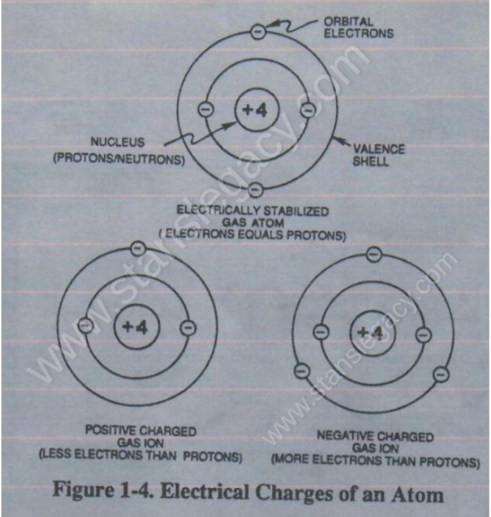
Atomic structure of an atom exhibits two types of electrical charged mass-entities, orbital electrons having negative electrical charges (-) and a Nucleus (at least one proton) having a positive electrical charge (+).
The positive electrical charge of the Nucleus equals the sum total of all negative electrical charged electrons when the Atom is in “stable-state.”
In stable-state or normal-state, the number of electrons equals the number of protons to give the atom “NO” net electrical charge.
Whenever one or more electrons are “dislodged” from the atom, the atom takes-on a net positive electrical charge and is called a positive ion.
If an electron combines with an stable or normal atom, the atom has a net negative charge and is called a negative ion.
Voltage potential within an electrical circuit can cause one or more electrons to be dislodged from the atom due to opposite electrical polarity attraction between unlike charged entities, as shown in Figure 1-5 (see Figure 1-3 again) as to Newton’s and Coulomb’s Laws of electrical-force.
 |
|
Newton’s and Coulomb’s Laws of electrical-force is used to combine or join atoms together by way of Covalent Bonding (opposite electrical forces) to form liquids, solids, or air.
The atom of Argon Gas (Ar) is, naturally, electrically stabilized when the number of electrons around the number of protons equal the atomic number of 18 on the Periodic Table of Elements.
The illustrated Argon Atom becomes electrical charged ion when the electron number changes from 18, as illustrated in Figure 1-4.
Gas Destabilization Process
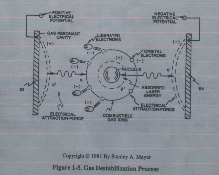 Placement of a pulse-voltage potential across the Excitor-Array (ER) of Gas Resonant Cavity (t) while inhibiting or preventing electron flow within the Voltage Intensifier Circuit (AA) causes the Gas Atom of Argon (Ar) to become an positive charged ion by pulling away orbital electrons from the gas molecule or gas atom, as illustrated in Figure 1-5.
The stationary "positive" electrical voltage-field (E3) attracts the negative charged electrons from the Gas Atom.
At the same time, the stationary "Negative" electrical voltage field (E4) attracts the positive charged nucleus of the gas atom (s).
Once the negative electrically charged electrons are dislodged from the gas atom, the gas atom becomes destabilized…having missing electrons.
Dislodging electrons from the gas atom by way of voltage stimulation is hereinafter called "The Gas Destabilization Process."
Attenuating and adjusting the "pulse-voltage-amplitude" with respect to the "pulse voltage frequency," now, regulates "The Electron Extraction Process."
LASER INTERACTION
Laser energy (v) of Figure 1-1 is now injected into or superimposed onto the Gas Destabilization Process to help promote the Electron Extraction Process since the absorbed light energy (electromagnetic energy) forces the gas atom electrons to an higher energy state or attraction-force (q2) between the orbital electrons and the nucleus…
weakening the electrical attraction-force (qq') between the orbital electrons and the nucleus, as illustrated in Figure 1-5 as to Figure 20JX.
|
|
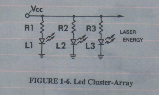 Light-emitting diodes arranged in an Cluster-Array provides and emits an narrow band of visible light energy, as illustrated in Figure 1-6 as to Figure 20XX.
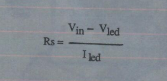
Laser or light intensity is linear with respect to the forward current through the LEDS, and, is determined by
Where
Iled is the specified forward current (typically 20ma. per diode);
Vled is the LED voltage drop (typically 1.7 volts for red emitters).
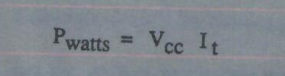
Ohm’s Law for LED circuit in parallel array, and, is given by
Where
It is the forward current through LED cluster-Array;
VCC is volts applied (typically 5 volts).
Electron Extraction Process
Whereby
Laser or light intensity is variable as to duty cycle on/off pulse-frequency from 1 Hz to 65 Hz and above, and, is given by
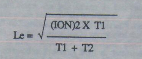
Le is light intensity in watts; T1 is current on-time; T2 is current off-time; and (ION) = RMS value of load current during on-period.
By varying or regulating laser intensity in direct relationship to applied pulse-voltage frequency and voltage amplitude causes the inert gas atom of Argon (Ar) to become a positive charged gas ion having missing electrons.
The Gas Destabilization Process with Laser Injection is, also, applicable to other types of airborne or free-floating atoms.
Electron Extraction Circuit (BB) of Figure 1-7 removes, captures, and consumes the "dislodged" electrons (from the gas atoms) to cause the gas atoms to go into and reach "ion-state," forming highly energized gas atoms having missing electrons.
Resistive values (R4, R6, R7, and dielectric constant of gas Rg) and isolated electrical ground (W) prevents "electron-flow" or "electron deflection" from occurring within circuit (BB) during pulsing operations (at resonant frequency) and, therefore, keeps the gas atoms in ion state by "NOT" allowing electron replacement to occur or take place between the moving gas atoms.
The "dislodged" negative charged electrons are "destroyed" or "consumed" in the form of "heat" when Amp Consuming Device (S) (such as a light bulb) is positive electrically energized during alternate pulsing operations.
Laser activated or laser primed gas ions repels the "dislodged" electrons being consumed, as illustrated in Figure 1-5.
The Electron Extraction Process (BB) is, hereinafter, called "The GAS RESONANT CAVITY," as illustrated in Figure 1-7 as to Figure 20JX.
|
 |
Magnetic Gas Lattice
 The forming Argon ion (Ar+) is now exposed to Iron ions (Fe+) (magnetic properties) experiencing and undergoing the same Electron Extraction Process.
Together, the two ions (Ar+/Fe+) form a covalent link up or covalent bond when the covalent electron of the Argon ion (Ar+) pair up and be shared with the valence electron of the Iron ion (Fe+).
Covalent bonding of Iron ions (Fe+) to the Argon ion (Ar+) continues until a geometrical Gas-Lattice Structure is formed, as illustrated in Figure 1-8.
Stable-state of the Gas-Lattice occurs when the covalent shell of each unlike atom structure becomes full or filled up… the Argon atom (Ar) sees an covalent shell of 8 electrons while, at the same time, the Iron atom (Fe) sees an covalent shell (M shell) of 14 electrons.
Covalent bonding between like atoms does not occur due to the “stronger” Electrical Attraction-Force (qq') between the unlike atoms.
During Gas-Lattice formation, Iron ions (Fe+) can be replaced by other atoms exhibiting magnetic properties such as Nickel ions (Ni+) or Cobalt ions (Co+).
Gas-Lattice formation of unlike atoms by way of the Electron Extraction Process is, hereinafter, called "The Gas Bonding Process".
Electromagnetic Enhancement
The newly "structured" Gas-Lattice becomes magnetized when, momentarily, exposed to a magnetic field, as illustrated in Figure 1-9.
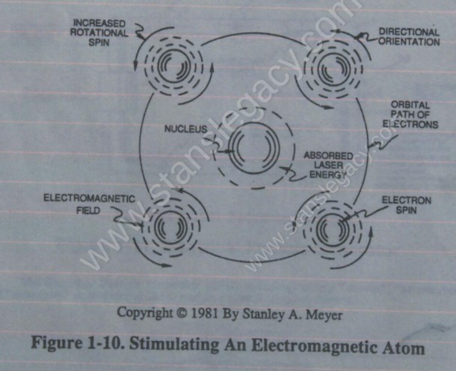
Since the electrons of the Iron ion (Fe+) spin in one direction only (SEE FIGURE 1-10) (Nickel ions and Cobalt ions in like manner), the magnetic field of each Iron ion (called Domains) unite and form a "Discrete" magnetic field called an "Magnetic Flux-Line".
|
|
 |
The Magnetic Flux Line follows the alignment of the Iron ions (Fe+ xxx Fe+) since Argon ions (Ar+ xxx Ar+) act as an "insulator" to the flow of magnetic Flux-Lines.
The Argon atom electrons tend to pair-off in orbits with opposite spins… preventing the formation of a second magnetic field.
Grouping the Magnetic Flux-Lines together forms an "Stable" magnetic field since the magnetic coupling-field between the Iron ions or Domains help to hold the Iron ions in an linear alignment beyond the bonding strength of the Gas-Lattice.
Magnetic Field Strength is "measured" in GAUSS UNITS and is determined by the linear volume of the Gas-Lattice.
Magnetic Field Enhancement
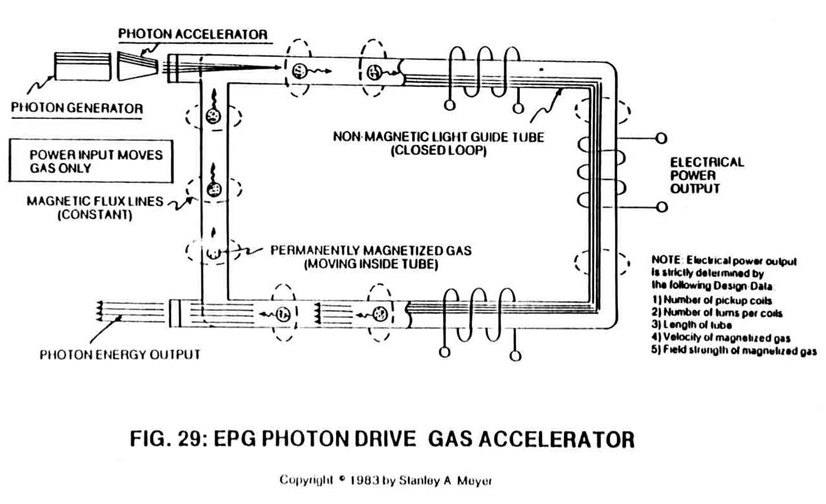
 Magnetic Field Enhancement occurs when the Magnetized Gas-Lattice (placed inside EPG close-loop tubular system) is exposed to and interacts with Laser energy, as illustrated in Figure 29 WFC Tech-brief.
The absorbed Laser energy forces the Iron ions' ELECTRONS to spin at a faster rate when taken to a higher energy level, which, in turn, amplifies and strengthens the magnetic field (Domain magnetic field) of the Iron ions.
The spinning electrons simply interact with both electrostatic forces and electromagnetic forces to produce an enhanced magnetic field.
This magnetic process is an extension of "The Electron Theory Of Magnetism".
Increasing Laser intensity increases the magnetic field strength of the gas-lattice in a linear function. NICKEL IONS and COBALT IONS are interchangeable with and duplicate the magnetic properties of Iron ions undergoing Laser priming.
 In Quiescent-State, the laser energy is superimposed onto the Gas-Lattice and "stored" inside the close-loop tubular EPG system to maintain a given or predetermined magnetic field strength during EPG operations.
In Active-State, the laser energy is pulsed and passes through the Gas-Lattice to produce a magnetic pulse-wave, as illustrated in Figure 29 as to Figure 26A and 26B.
 |
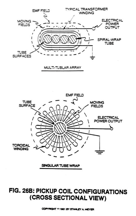 |
In either case, the resultant magnetic field transverses pickup-coils to produce electrical energy.