| **Laser Accelerator Assembly** (20) of Figure (3-10) [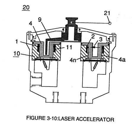](https://stanslegacy.com/uploads/images/gallery/2023-12/0bZIjzhQfoac5KO6-image-1703381224678.png) | **SDP8611 Optoschmitt light receiver** (2) of Figure (3-9) [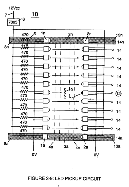](https://stanslegacy.com/uploads/images/gallery/2023-12/eqE5Dz27qkVqIGiU-image-1703374881884.png) |
The peak **wavelength** (3) of Figure (3-9) being transmitted from the infrared emitting diode (led) (1) to the **Optoschmitt receiver** (2) is typically (935 nm) and allows the **Optoschmitt** (2) clock frequency (the speed by which the Optoschmitt changes logic state) to be (100 kHz).
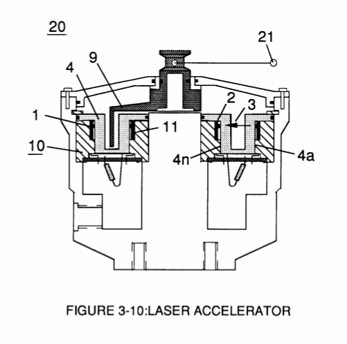
**Optical lens** (4) of Figure (310) redirects and focuses the **transmitted light source** (3) of Figure (3-9) (traveling infrared light waves) to the **Optoschmitt** (2) by passing the light source through a series of **concentric lenses** (4a xxx 4n) of Figure (3-10) which become progressively smaller from the **outer peripheral lens surface** (4a) to the **inner lens surface** (4n). [](https://stanslegacy.com/uploads/images/gallery/2023-12/0bZIjzhQfoac5KO6-image-1703381224678.png)The **spatially concentric lenses** (4a xxx 4n) of Figure (3-10) causes the beam angle of the light source to trigger the **Optoschmitt** (2) beyond the minimum irradiance that is needed to switch the Optoschmitt from **quiescent state** (high logic state I B+ ) to **on-state** (output changing to zero volts).The **Derate linearly** of light intensity is approximately 1.25mWj degree C above 25 degree C at a spatial distance of .500 inches between the **two infrared devices** (1)(2) of Figure (3-9) as to Figure (3-10).
**Transmitted light source** (3) is turned-on when a electrical power source of 5 volts is applied to the **led** (1) through **dropping resister** (5) by way of **voltage regulator** (6) connected to the car **electrical system** (7). Together, the **matched infrared devices** (1)(2) with **optical lens** (4) forms **optical circuit** (8) of Figure (3-9).Grouping additional **optical circuits** (8a xxx 8n) in an inline or linear arrangement, now, forms **Led Pickup Circuit** (10) of Figure (3-9), as shown in Figure assembly (20) of Figure (3-10).
| **Led Pickup Circuit** (10) of Figure (3-9) [](https://stanslegacy.com/uploads/images/gallery/2023-12/eqE5Dz27qkVqIGiU-image-1703374881884.png) | Figure assembly (20) of Figure (3-10) [](https://stanslegacy.com/uploads/images/gallery/2023-12/0bZIjzhQfoac5KO6-image-1703381224678.png) |
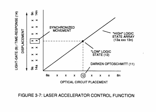
Advancing **light-gate** (9) still further performs the same opposite (alternate) logic-state switching in a sequential manner until the advancing **light-gate** (9) reaches the **last optical circuit** (8n).
Reversing the movement of **light gate** (9) performs the same high to low logic switch-function but in reverse sequential order. Reversing the direction of the **light-gate** (9) once again reinstates the original sequential switching order, as illustrated in Figure (3-7) and Figure (3-9).Longevity and reliability of component life is typically 100,000 hours since led pickup circuit (10) of figure (3-9) utilizes no mechanical contacts to perform the sequential logic switch function.
**[](https://stanslegacy.com/uploads/images/gallery/2023-12/0bZIjzhQfoac5KO6-image-1703381224678.png)Light-gate** (9) integrated with **led pickup circuit** (10) make up **Laser Accelerator assembly** (20), as shown in Figure (3-10). **Light-gate** (9) of Figure (3-10) is mechanically linked to the car acceleration pedal by way of **cabling hookup** (22). Opposite placement of the **matched infrared devices** (1)(2) prevents bogus or false triggering of "low" **logic state** (12) during **light-gate displacement** (9a xxx 9n) of Figure (6)(7) and (8). If light emitting diodes (led) (la xxx In) of figure (8) are electrically disconnected from D.C. power supply (6), then **Led Pickup Circuit** (10) outputs are switch to "low" logic state (l2a xxx 12n) which disallows "low" **logic state signal** (12), resulting in a "shut-down" condition to **Hydrogen Gas Control Circuit** (200) of Figure (3-1). [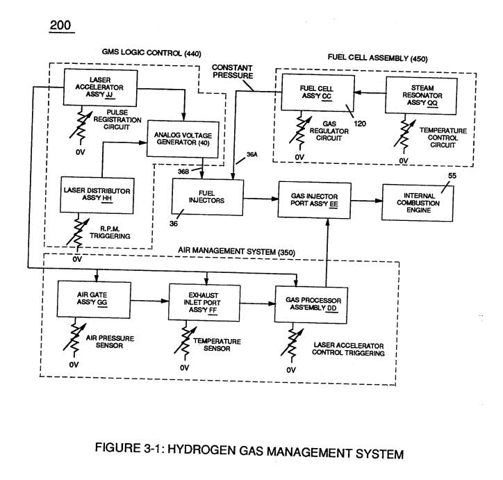](https://stanslegacy.com/uploads/images/gallery/2023-12/2npurKubUvEXMU5s-image-1703381503607.png) Disconnection of **power supply** (6) to **Optoschmitt array** (2a xxx 2n) of Figure (3-9) results in a similar "shut down" condition to **control circuit** (200), as further shown in Figure (3-1).This "shut-down" or "Switch-off" condition helps provide a fail-safe operable **Fuel Cell** (120) of Figure (3-20) by negating acceleration beyond driver's control.
# Acceleration Control Circuit (30) Moving **light-gate** (9) of figure (3-9) in direct relationship to the physical placement of **optical circuits** (8a xxx 8n), sets up a **time variable** (14a xxx 14n) of Figure (3-7) from **optical circuits** (8x) to another **optical circuit** (8xx) and/ or (8xxx) or to (8n) since the triggered **low logic state** (12) of Figure (3-7) and (3-8) moves in direct relationship to the displaced **light-gate** (9), as illustrated in Figure (3-12).| Figure (3-7) [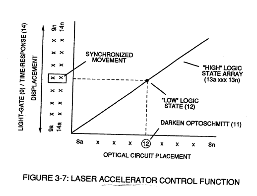](https://stanslegacy.com/uploads/images/gallery/2023-12/TUF7LkkiUSFT4h2x-image-1703374861011.png) | Figure (3-8) [](https://stanslegacy.com/uploads/images/gallery/2023-12/pjxVw7assd34zNNX-image-1703374870146.png) |
| Figure (3-9) [](https://stanslegacy.com/uploads/images/gallery/2023-12/eqE5Dz27qkVqIGiU-image-1703374881884.png) | Figure (3-12) [](https://stanslegacy.com/uploads/images/gallery/2023-12/bBte9bH1vjrh9pO1-image-1703374892948.png) |
Deflecting (moving) the **light-gate** (9) to **position** (8n) takes longer in **response-time** (14n) than deflecting the light-gate to position (8x) and/or (8xx) or (8xxxx).
This variable **response-time** (14axx ... 12 ... xxI4n) or **signal output** (15) of Figure (3-5) is, now, electrically transmitted to **Acceleration Control Circuit** (30) of Figure (3-5) since **Laser Accelerator Assembly** (20) of figure (3-10) converts **mechanical displacement** (9a xxx 9n) to **electrical time-response** (14a xxx 14n) of Figure (3-7) by linearly moving (forward and/or reverse direction) "low" **logic state signal** (12) in a array of "high" logic state **output signals** (13a xxx 13n), as further illustrated in Figure (3-8) and Figure (3-12).| Figure (3-7) [](https://stanslegacy.com/uploads/images/gallery/2023-12/TUF7LkkiUSFT4h2x-image-1703374861011.png) | Figure (3-5)[](https://stanslegacy.com/uploads/images/gallery/2023-12/vFSFXV3sntA7ICZs-image-1703375068946.png) |
| Figure (3-8) [](https://stanslegacy.com/uploads/images/gallery/2023-12/pjxVw7assd34zNNX-image-1703374870146.png) | Figure (3-12) [](https://stanslegacy.com/uploads/images/gallery/2023-12/5uNuLwkNkx6jxXkA-image-1703375156797.png) |
Circuit (30) electronically and automatically scans **output signal-array** (14axxx ... 12 ... xx14n) (15) until **circuit** (30) locates, **momentarily registers**, and translates **response-time** (14a xxx ... 12) into a **variable unipolar pulse** (17/18) of Figure (3-8).
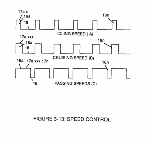
The sweeping action of the **scanning circuit** (30) always starts from **position** (9a) and moves **point** (8ax) to **point** (8axxx) of Figure (3-9) (3-12) until **logic-point** (12) is detected. Once **logic signal** (12) is detected, the sweeping action toggles and recycles back to **start-position** (9a). This toggling (*flip back*) action electronically determines **variable time-response** (14a xxx) regardless of wherever logic point (12) is being momentarily displaced within **circuit array** (13a xxx 13n). **[](https://stanslegacy.com/uploads/images/gallery/2023-12/pjxVw7assd34zNNX-image-1703374870146.png)Toggling action** at full-scale **deflection** (13a xxx 13n) occurs in the range of (10) kHz or above and thus, allows instant response to driver's acceleration demands. **Toggling-time** (scanning-time) is directly synchronized to **light gate** (9) displacement which, in turns, **circuit** (30) further sets up and establishes a given **pulse shape** (16) of Figure (3-8). **Circuit** (30) continues to increase **pulse width** (17axxxx) of Figure (3-8) as the monitored (*detected by < scanning*) **toggling-time** (14a xxxx ... 12) increases when **logic-point** (12) moves farther away from **start-position** (9a) to **stop-position** (9n), as further shown in Figure (3-13) as to Figure (3-12).**Pulse width** (17a xxx 17n) diminishes when **logic-point** (12) reverses direction to start .. **position** (9a).
| Figure (3-12)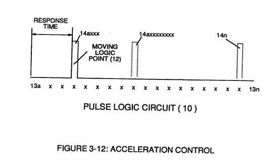 | Figure (3-13)[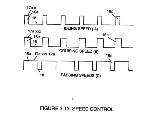](https://stanslegacy.com/uploads/images/gallery/2023-12/BP6hCkX2nps5ADCT-image-1703375624884.png) |
Finally, **circuit** (30) reproduces the **variable controlled pulse-shape** (16) in a continuous **repetitive manner** (16a xxx 16n) of Figure (3-13) and electrically transmits the resultant **pulse-train signal** (19) to **Analog Voltage Circuit** (40), as shown in Figure (3-5).
| Figure (3-13) [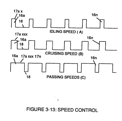](https://stanslegacy.com/uploads/images/gallery/2023-12/kaBCr5103gLcMT1t-image-1703194915396.png) | **Analog Voltage Circuit** (40), as shown in Figure (3-5) [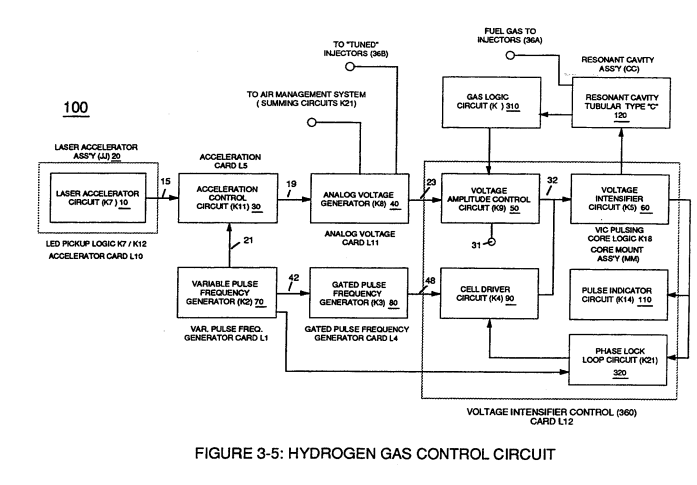](https://stanslegacy.com/uploads/images/gallery/2023-12/YkkFL3H6bzsH65A5-image-1703194897766.png) |
In retrospect to **engine performance** (*gas pedal attenuation*) (21) of Figure (3-10), a wider **pulse width** (17a xxx) of Figure (3-13C) increases (*accelerates*) engine R.P.M.; whereas, smaller **pulse-width** (17ax) reduces (de-accelerates) engine R.P.M .. Cruising speed (3-13B) of Figure (3-13) is simply accomplished when pulse width remains constant.
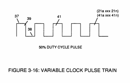
Incoming **clock pulse** (21a xxx 21n) of Figure (3-16) originating from **Pulse Frequency Generator** (70) of| Figure (3-16) [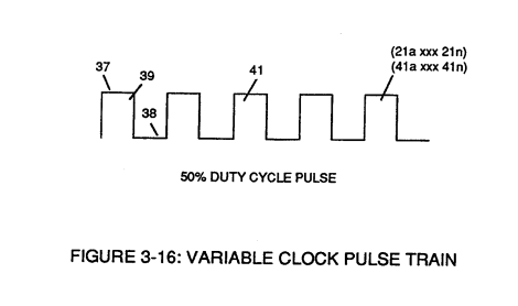](https://stanslegacy.com/uploads/images/gallery/2023-12/uPM4NAOKxNgpKeiA-image-1703375884091.png) | Figure (3-5) [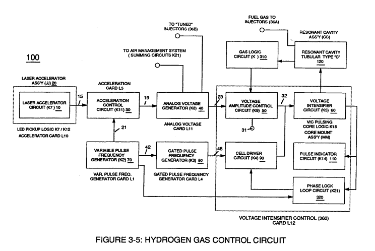](https://stanslegacy.com/uploads/images/gallery/2023-12/pkENicyNmypUexcX-image-1703375903506.png) |
The resultant **clock pulse** (21) of Figure (3-16) as to Figure (3-5) is always adjusted to exceed driver's response time to allow for instant acceleration control.
# Analog Voltage generator (40) The generated **digital signal** (19) being electrically transmitted from **accelerated control circuit** (30) of Figure (3-5) is, now, electronically detected, translated, and converted into a **analog voltage signal** (22) which is continuously proportionate to **input signal** (19) by **Analog Voltage Generator Circuit** (40) of Figure (3-5). [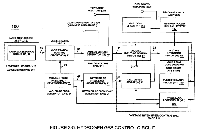](https://stanslegacy.com/uploads/images/gallery/2023-12/d5x6lw5jRAJT48i1-image-1703195613050.png) The newly formed **analog signal** (22) of Figure (3-14) is a voltage level signal that varies continuously in both time and amplitude to produce a voltage level which is directly proportional to the physical change in **pulse train** (100 xxx 16n) of Figure (3-13).| Figure (3-13) [](https://stanslegacy.com/uploads/images/gallery/2023-12/kaBCr5103gLcMT1t-image-1703194915396.png) | Figure (3-14) [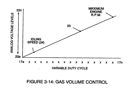](https://stanslegacy.com/uploads/images/gallery/2023-12/prG7V9Hd24ooi89W-image-1703195335274.png) |
The resultant and varied **voltage level** (22a xx) varies smoothly over a continuous range of **voltage valves** (22a xxx 22n) *rather than in discrete steps*, as illustrated in linear graph (23) of Figure (3-14).
In terms of functional-ability and purpose, **analog circuit** (40) of Figure (3-5) provides a variable (controlled) **voltage output** (23) in direct relationship to light gate (9) displacement which, in turns, sets up and controls **Resonant Action** (160) of Figure (3-23) that produces **Fuel Gases** on demand.
**[](https://stanslegacy.com/uploads/images/gallery/2023-12/prG7V9Hd24ooi89W-image-1703195335274.png)Analog circuit** (40) also calibrates both **engine idling speed** (22ax) and **maximum engine R.P.M.** (22a xxx 22n) by adjusting and maintaining a predetermined or given **low** (24) and **high** voltage levels respectively, as further illustrated in Figure (3-14).**Voltage valves** or **levels** (22a xxx 22n) simply controls the applied voltage potential across **Resonant Cavity Assembly** (120) of Figure (3-22) through **voltage amplitude control circuit** (50) of Figure (3-5) which is is electrically linked to **primary coil** (26) of Figure (3-22) of **Voltage Intensifier Circuit** (60) of Figure (3-5).
| Figure (3-22) [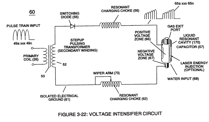](https://stanslegacy.com/uploads/images/gallery/2023-12/8ATrN3YcXfGXz0Kt-image-1703196300438.png) | Figure (3-5) [](https://stanslegacy.com/uploads/images/gallery/2023-12/d5x6lw5jRAJT48i1-image-1703195613050.png) |
| Figure (3-21) [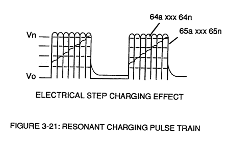](https://stanslegacy.com/uploads/images/gallery/2023-12/uie7yJbd501dcf86-image-1703197617452.png) | Figure (3-22) [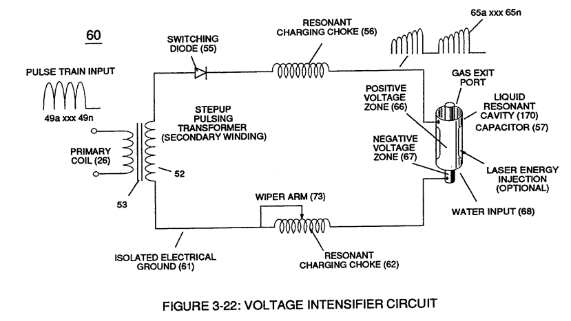](https://stanslegacy.com/uploads/images/gallery/2023-12/QHMK3ysi5cLB805A-image-1703197630289.png) |
**Regulator stage** (27) of **circuit** (50) converts **battery voltage potential** (29) of Figure (3-6) via **electrical terminal** (31) of Figure (3-5) as to Figure (3-6) into a **analog voltage signal** (32) of Figure (3-15) which corresponds to but is **electrically isolated** (*crossover voltage from two separate power supplies*) from incoming **gas volume signal** (23) of Figure (3-14), as shown in Figure (35).
**Variable voltage range** (32a xxx 32n) from **one** (1) up to **twelve** (12) volts (regulating battery voltage) is applied across **primary coil** (26) of **Voltage Intensifier Circuit** (60) of Figure (3-21). Second **regulator stage** (28) simply acts and function as a **gas regulator** (33) by preventing **Fuel Gas** production beyond a predetermined **gas pressure level** (34) of Figure (3-15) during **Fuel Cell** operations and, as such, maintains constant gas pressure to **Fuel Injectors** (36) of Figure (3-1) regardless of engine performance (R.P.M. response).If for example, **Fuel Gas** production is greater than demand, then, **analog signal** (32) is reduced to proper **voltage level** (35) (voltage level directly determines gas pressure via **Resonant Action**) required to maintain **gas pressure** (34).
Conversely, **analog signal** (32) is always allowed to exceed **voltage level** (35) during **injection** (36) of Figure (3-1) until **gas-point** (34) is reached.In cases where **linear voltage** (32) drops (descending value) below **gas-point** (35) then **gas regulator stage** (28) increases **voltage amplitude** (32a xxx 32n) (analog voltage) to **voltage point** (35).
If **gas pressure** (34a xx) should exceed **gas point** (35) during injector off-time, **gas pressure release valve** (75) of Figure (3-24) (**gas venting** 37 of Figure 3-15) expels **Fuel gases** (88) until **gas point** (34) is either reached or a delay timing circuit activates **Safety Control Circuit** (14) of Figure (3-6) which, in turns, switches off or disconnects **applied electrical power** (28) to **Fuel Cell electrical system** (400) of Figure (3-6).| Figure (3-15) [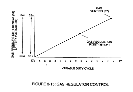](https://stanslegacy.com/uploads/images/gallery/2023-12/q8NhrnLpRbNYf6ta-image-1703197371585.png) | Figure (3-6) [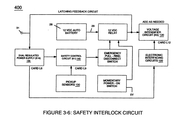](https://stanslegacy.com/uploads/images/gallery/2023-12/svIAaiYbAQpJY3rv-image-1703197390102.png) |
| Figure (3-1) [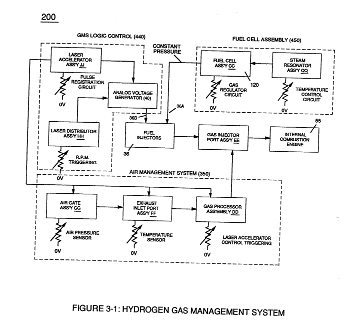](https://stanslegacy.com/uploads/images/gallery/2023-12/QW9gvbrkDyzcsRDF-image-1703197200823.png) | Figure (3-24) [](https://stanslegacy.com/uploads/images/gallery/2023-12/1WXhsCSuTnngaFfo-image-1703197217269.png) |
In terms of operability, **Laser Accelerator Assembly** (20) of Figure (3-5) is, now, attenuating **battery voltage potential** (32a xxx 32n) which is electrically connected to **Voltage Intensifier Circuit** (60) of Figure (3-5).
[](https://stanslegacy.com/uploads/images/gallery/2023-12/d5x6lw5jRAJT48i1-image-1703195613050.png) # Variable Pulse Frequency Generator (70) **Circuit** (70) of Figure (3-5) is a **multi pulse-frequency generator** which produces several clock pulses (*simultaneously*) **having different pulse-frequency** but maintaining a 50% duty cycle pulse (39) configuration, as illustrated in Figure (3-16).| Figure (3-5) [](https://stanslegacy.com/uploads/images/gallery/2023-12/d5x6lw5jRAJT48i1-image-1703195613050.png) | Figure (3-16) [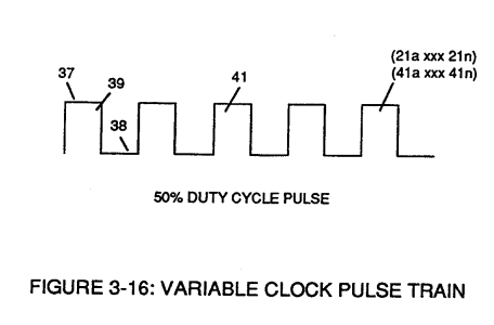](https://stanslegacy.com/uploads/images/gallery/2023-12/9eo48JVGQNzatQ86-image-1703198042496.png) |
Newly formed **gated duty pulse** (45) is proportional to the physical change in **pulse train** (44a xxx 44n) when **circuit** (80) is adjusted for calibration purposes.
**Pulse train** (44a xxx 44n) becomes **widened** while **pulse off-time width** (43) becomes **smaller**, simultaneously.
Conversely, opposite **pulse shaping occurs** when **circuit** (80) of Figure (3-5) is **calibrated in reverse** **order**.
# Cell Driver Circuit (90) In either case, the resultant or varied **pulse train** (47a xxx 47n) (*calibration of 44a xxx 44n*) becomes **incoming gated pulse signal** (48) of figure (3-5) to **cell driver circuit** (90) of Figure (3-5) which performs a switching function by switching "**off**' and "**on**" electric ground being applied to **opposite side** (48) of **primary coil** (26) of Figure (3-19).| Figure (3-18) [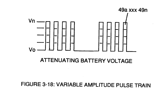](https://stanslegacy.com/uploads/images/gallery/2023-12/perOMBdYqG5zfDB2-image-1703200544967.png) | Figure (3-19) [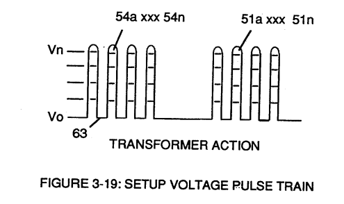](https://stanslegacy.com/uploads/images/gallery/2023-12/UateQAwSqhsH4mKF-image-1703200555466.png) |
However, each **pulse train** (47) (49) are electrically isolated from each other.
Only voltage cross-over from regulated **power supply** (150) of Figure (3-6) to **battery supply** (28) occurs, as illustrated in Figure (3-6).| Figure (3-6)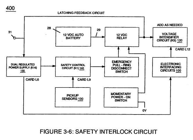 | Figure (3-5) |
| Figure (3-15) [](https://stanslegacy.com/uploads/images/gallery/2023-12/q8NhrnLpRbNYf6ta-image-1703197371585.png) | Figure (3-18) [](https://stanslegacy.com/uploads/images/gallery/2023-12/perOMBdYqG5zfDB2-image-1703200544967.png) |
| Figure (3-19) [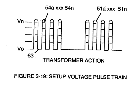](https://stanslegacy.com/uploads/images/gallery/2023-12/ojTv41ralWh4qvQC-image-1703203837958.png) | Figure (3-22) [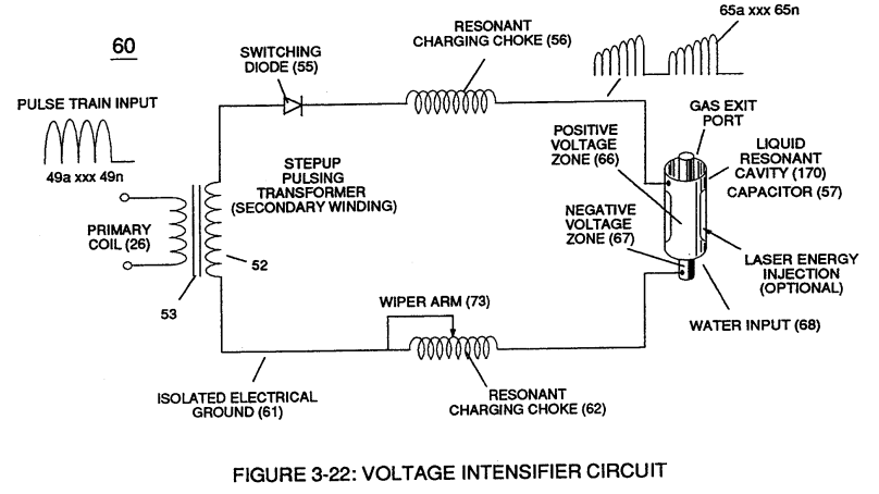](https://stanslegacy.com/uploads/images/gallery/2023-12/K7QoIRjYjGqOS8C3-image-1703201617139.png) |
**Analog voltage signal** (32a xxx 32n) of Figure (3-15) allows **pulse train** (51a xxx 51n) **voltage amplitude** (V0 xxx Vn) of Figure (3-19) to vary from **one** up to **twelve** volts *(battery supply 28 of Figure 3-6* by attenuating **Laser Accelerator circuit** (10) of Figure (3-5) via **Hydrogen Gas Control Circuit** (100).
| Figure (3-15) [](https://stanslegacy.com/uploads/images/gallery/2023-12/q8NhrnLpRbNYf6ta-image-1703197371585.png) | Figure (3-5) [](https://stanslegacy.com/uploads/images/gallery/2023-12/d5x6lw5jRAJT48i1-image-1703195613050.png) |
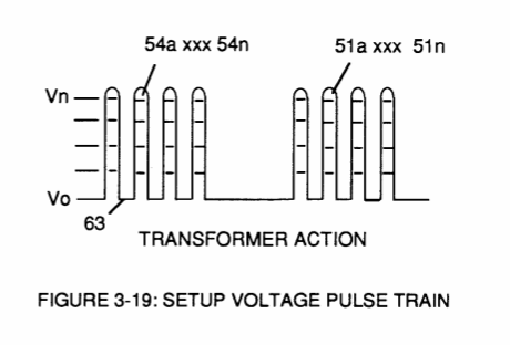
**Variable pulse frequency generator** (70) of Figure (3-5) varies and adjusts **pulse frequency** (63) *(50% duty cycle pulse)* while **gated pulse frequency generator** (80) of Figure (3-5) varies and adjusts **pulse width** (54a xxx 54n).
These controlled and variable pulse features are, now, translated to **Resonant Charging pulse train** (65a xxx 65n) of Figure (3-21) via **Unipolar pulse train** (64a xxx 64n) of Figure (3-20) during **Resonant Action** (160) of Figure (3-26) when signal coupling is applied across **Resonant Cavity** (170) of Figure (3-24) via **positive voltage zone** (66).| Figure (3-21) [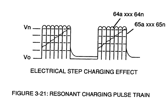](https://stanslegacy.com/uploads/images/gallery/2023-12/qZcJcpsQWujxY3uB-image-1703202650133.png) | Figure (3-20) [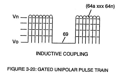](https://stanslegacy.com/uploads/images/gallery/2023-12/1uHRCvzqaVhAKGH6-image-1703204498070.png) |
| Figure (3-26) [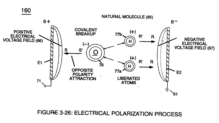](https://stanslegacy.com/uploads/images/gallery/2023-12/JEtePO4SKkPGZWRI-image-1703203395676.png) | Figure (3-24) [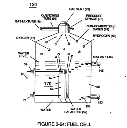](https://stanslegacy.com/uploads/images/gallery/2023-12/SfsY9Ms8MRP5eM0o-image-1703197304479.png) |
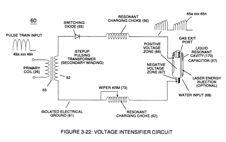
**Negative electrical voltage potential** (61) of **pulse wave** (65a xxx 65n) of Figure (3-21) is simultaneously applied to **negative voltage zone** (67) via **Resonant Charging Choke** (62) of Figure (3-22) which is electrically linked to opposite end of **Primary Coil** (26).
The resultant **signal coupling** ( 65a xx 65n ) of Figure (3-21) is accomplished since **primary coil** (26), **pulsing core** (53), **secondary coil** (52), **switching diode** (55), **resonant charging choke** (56), **resonant cavity assembly** (170), **natural water** (68), and **variable resonant charging choke** (62) forms **Voltage Intensifier Circuit** (60) of Figure (3-22), as illustrated in Figure (3-22) as to Figure (3-23).
| Figure (3-22) [](https://stanslegacy.com/uploads/images/gallery/2023-12/K7QoIRjYjGqOS8C3-image-1703201617139.png) | Figure (3-23) [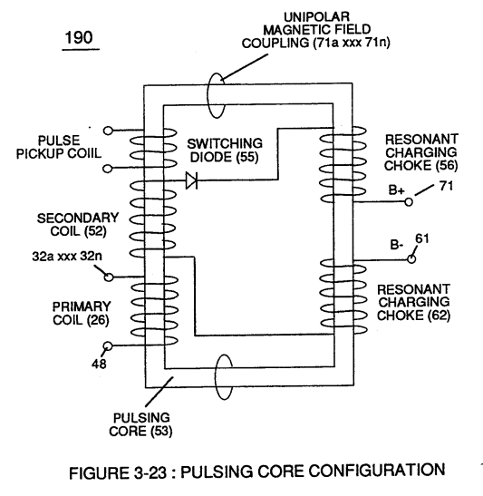](https://stanslegacy.com/uploads/images/gallery/2023-12/Tus1Xr1U62DJCsDx-image-1703201534713.png) |
**Negative electrical ground** (61) of **voltage Intensifier circuit** (60) of Figure (3-22) is electrically isolated from **primary electrical ground** (48) of Figure (3-22).
**Pulsing transformer** (26/52) of Figure (3-22) steps up voltage amplitude or **voltage potential** (Vo xxx Vn) of Figure (3-19) during pulsing operations. **Primary coil** (26) is electrically isolated (*no electrical connection between primary 26 and secondary coil)* to form **Voltage Intensifier Circuit** (60) of Figure (3-22). Voltage amplitude or **voltage potential** (Vo xxx Vn) is increased when **secondary coil** (52) is wrapped with more turns of wire.**Isolated electrical ground** (61) prevents electron flow from **input circuit ground** (48).
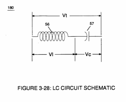
**[](https://stanslegacy.com/uploads/images/gallery/2023-12/K7QoIRjYjGqOS8C3-image-1703201617139.png)Switching diode** (55) of Figure (3-22) not only acts as a blocking diode by preventing electrical "**shorting**" to **secondary coil** (52) during **pulse off-time** (69) of Figure (3-20) since **diode** (55) "only" conducts electrical energy in the direction of schematic arrow; but, also, and at the same time functions as an **electronic switch** which opens **electrical circuit** (60) during **pulse off-time** ...allowing magnetic fields of both **inductor coils** (56/57) to collapse ... forming **pulse train** (64a xxx 64n).**Resonant charging choke** (56) in series with **Excitor-Array** (160) of Figure (25) forms an **inductor-capacitor circuit** (180) of Figure (3-28) since **Excitor-Array** (66/67) acts and performs as a capacitor (*dielectric liquid between opposite electrical plates*) during pulsing operations.
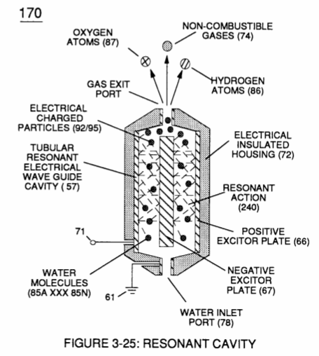
[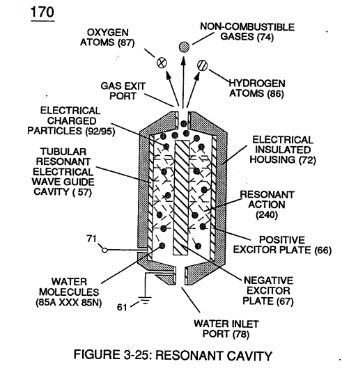](https://stanslegacy.com/uploads/images/gallery/2023-12/jmc1Z2WkjHNbWiZ6-image-1703201429384.png)The **dielectric properties** (*insulator to the flow of amps*) of **natural water** (68) of Figure (3-28) as to Figure (3-26) > *(dielectric constant of water being 78.54 @ 20C in 1-atm pressure)* between **electrical plates** (66/67) forms **capacitor** (57), as illustrated in (170) of Figure (3-25).| Figure (3-26) [](https://stanslegacy.com/uploads/images/gallery/2023-12/JEtePO4SKkPGZWRI-image-1703203395676.png) | Figure (3-28) [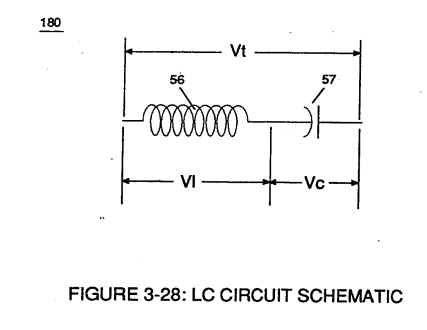](https://stanslegacy.com/uploads/images/gallery/2023-12/8IJsOVAmLG4LJk6U-image-1703203073889.png) |
Water now becomes part of **Voltage Intensifier circuit** in the form of "**resistance**" between **electrical ground** (67) and **pulse-frequency positive potential** (66) ... helping to prevent electron flow within **pulsing circuit** (60) of Figure (3-22).
**Inductor** (56) and **capacitor** (57) properties of LC circuit (180) is therefore "**tuned**" to resonate at a given frequency. **Resonant frequency** (63) of Figure (3-19) can be raised or lowered by changing the **inductance** (56) and/or **capacitance** (57) **valves**.The established **resonant frequency** is, of course, independent of voltage amplitude, as illustrated in Figure (3-21) as to Figure (3-18).
| Figure (3-21) [](https://stanslegacy.com/uploads/images/gallery/2023-12/qZcJcpsQWujxY3uB-image-1703202650133.png) | Figure (3-18) [](https://stanslegacy.com/uploads/images/gallery/2023-12/perOMBdYqG5zfDB2-image-1703200544967.png) |
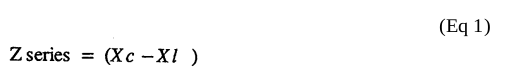
The impedance of **inductor** (56) and **capacitor** (57) in series, Z series is given by (Eq 1)
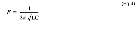
[](https://stanslegacy.com/uploads/images/gallery/2023-12/6bTQI1dpHoy0l7Xk-image-1703202839633.png)where **Resonant frequency** (63) of LC circuit in series is given by (Eq 4)
[](https://stanslegacy.com/uploads/images/gallery/2023-12/m9WaOO0dqMhRUide-image-1703202762309.png)Ohm's law of LC circuit (180) of Figure (3-28) in series is given by (Eq 5)
[](https://stanslegacy.com/uploads/images/gallery/2023-12/yGrIzleU35BEaBbL-image-1703202777342.png)The voltage across **inductor** (56) or **capacitor** (57) is greater than **applied voltage** (49) of Figure (3-18).
| Figure (3-18) [](https://stanslegacy.com/uploads/images/gallery/2023-12/perOMBdYqG5zfDB2-image-1703200544967.png) |
At frequency close to resonance, the voltage across the individual components is higher than **applied voltage** (49), and, at resonant frequency, the **voltage** (Vt) of Figure (3-28) across both **inductor** and the **capacitor** are *theoretically infinite*.
However, **physical constraints** of components and circuit interaction prevents the voltage from reaching infinity.
The **voltage** (VI) across **inductor** (56) is given by equation (Eq 6)
[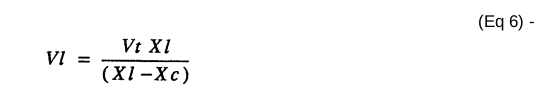](https://stanslegacy.com/uploads/images/gallery/2023-12/0S6vXBrg4ZRYjrkH-image-1703202464751.png)**Voltage** (Vc) of Figure (3-28) across the **capacitor** is given by (Eq 7)
[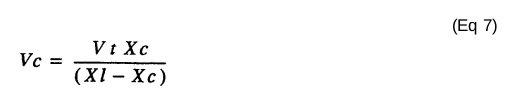](https://stanslegacy.com/uploads/images/gallery/2023-12/o65BVW3T4uncBvSv-image-1703202477600.png) During resonant interaction, the **incoming unipolar pulse train** (64a xxx 64n) of Figure (320) as to Figure (3-21) produces a **step charging voltage effect** across **excitor-array** (66/67) (57) as so illustrated in Figure (3-21).| Figure (3-21) [](https://stanslegacy.com/uploads/images/gallery/2023-12/qZcJcpsQWujxY3uB-image-1703202650133.png) |
**Voltage intensity** increases from **zero** "**ground-state**" to a **high positive voltage potential** in an progressive function.
Once **voltage-pulse** (64) is terminated or switch-off, **voltage potential** returns to "**ground-state**" (61) or near ground-state *(**diode** 55 maintains voltage charged across capacitor 57)* to start the voltage deflection process over again as pulse train (64a xxx 64n) continues to be duplicated.
"Voltage intensity or level across **excitor array** (57) can *exceed 20,000 volts* due to **circuit** (60) interaction and is directly related to **pulse train** (64a xxx 64n) **variable amplitude** input.
**Inductor** (56) is made of or composed of **resistive wire** to further restrict D.C. current flow beyond **inductance reaction** (Xl), and, is given by (Eq 8) [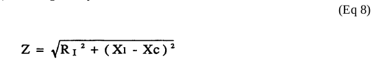](https://stanslegacy.com/uploads/images/gallery/2023-12/d2Puqn7VvWKdh4XB-image-1703202206972.png) **[](https://stanslegacy.com/uploads/images/gallery/2023-12/K7QoIRjYjGqOS8C3-image-1703201617139.png)Variable inductor-coil** (62) of Figure (3-22), similar to **inductor** (56) connected to **opposite polarity voltage zone** (67) further inhibits electron movement or **deflection** within **voltage intensifier circuit** (60).**Movable wiper arm** (73) of Figure (3-22) fine "tunes" "**resonant action**" during pulsing operations.
**Inductor** (62) in relationship to **inductor** (56) electrically balances the **opposite electrical potential** across **voltage zone (**66/67).
Since **pickup coil** (52) is also composed of or made of **resistive wire-coil**, then, **total circuit resistance** is given by (Eq 9)
[](https://stanslegacy.com/uploads/images/gallery/2023-12/Ckks49Ih0Dt6GhuX-image-1703201978946.png)where, RE is the **dielectric constant** of natural water.
Ohm's law as to **applied electrical power**, which is (Eq 10)
[](https://stanslegacy.com/uploads/images/gallery/2023-12/1AudiDYWkp7BubDT-image-1703201955646.png) where, (Eq 11) [](https://stanslegacy.com/uploads/images/gallery/2023-12/lLpTWNFW6aGZp7eV-image-1703201934685.png) Whereby,**electrical power** (P) is an linear relationship between two variables, **voltage** (E) and **amps** (I).
[](https://stanslegacy.com/uploads/images/gallery/2023-12/Tus1Xr1U62DJCsDx-image-1703201534713.png)Amp restriction *beyond* "**resonant action**" occurs when **unipolar magnetic field coupling** (71) of Figure (3-23) is allowed to simultaneously drop (*pulsating magnetic field*) across **both** **resonant charging chokes** (56/62) during pulsing operations since **electron mass** is an **electromagnetic entity** which is **subject to inductor fields** (56/62) produced by **pulsating magnetic field** (71a xxx 71n) of Figure (3-23).**Amp leakage** (*electron coupling to water*) **to water bath** (68) of Figure (3-24) is further prevented by encapsulating **resonant cavity** (57) in **delrin material** (72) of Figure (3-25) which is an electrical insulator to high voltage.
| Figure (3-24) [](https://stanslegacy.com/uploads/images/gallery/2023-12/1WXhsCSuTnngaFfo-image-1703197217269.png) | Figure (3-25) [](https://stanslegacy.com/uploads/images/gallery/2023-12/jmc1Z2WkjHNbWiZ6-image-1703201429384.png) |
**Delrin material** (72) **insulator value** remains intact since insulation material (72) is resilient to water absorption.
Inherently, then, **pulsing core** (53) of Figure (3-23) aids amp restriction while **voltage intensifier circuit** (190) is being "**tuned**" (*adjusting pulse train 49a xxx 49n pulse-frequency 63 via pulse frequency generator 70 of figure 3-5*) to match the resonant frequency properties of **water bath** (68) of Figure (3-22), as illustrated in **Fuel Cell** (120) of Figure (3-24).| Figure (3-22) [](https://stanslegacy.com/uploads/images/gallery/2023-12/K7QoIRjYjGqOS8C3-image-1703201617139.png) | Figure (3-23) [](https://stanslegacy.com/uploads/images/gallery/2023-12/Tus1Xr1U62DJCsDx-image-1703201534713.png) |
| Figure (3-22) [](https://stanslegacy.com/uploads/images/gallery/2023-12/K7QoIRjYjGqOS8C3-image-1703201617139.png) | Figure (3-27) [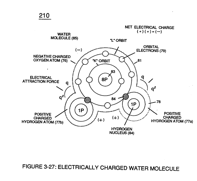](https://stanslegacy.com/uploads/images/gallery/2023-12/X69aZJeEKE3sC7yr-image-1703201640663.png) |
**Voltage potential** (65) is an "unaltered" or "unchanged" energy-state when "**electron movement**" or "**electron deflection**" is prevented or restricted within **electrical circuit** (190) of Figure (3-23).
| Figure (3-22)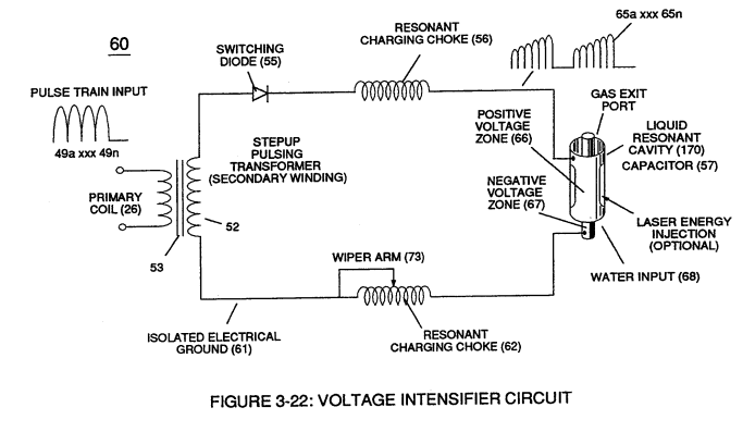 | Figure (3-23)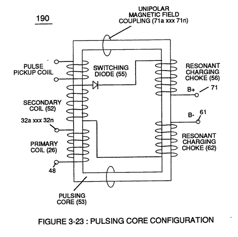 |
These electrical "**forces**" are known as ''**voltage fields**" and can exhibit either a **positive** (66) or **negative** (67) electrical charge.
Likewise, **Ions** or **charged particles** (*atoms having missing or sharing electrons between unlike atoms*) within **electrical circuit** (60) having unlike electrical charges are attracted to each other. **Ions** or **particle** **mass** having the same or like electrical charges will **move away** from one another, as illustrated in (220) of Figure (3-29).Furthermore, electrical charged **ions** or **particles** can move toward stationary voltage fields or **voltage zones** (66/67) of opposite polarity, and, is given by **Newton's second law** (Eq 12)
[](https://stanslegacy.com/uploads/images/gallery/2023-12/o7n7q3jbD3GdVPg3-image-1703232231619.png) Where, the **acceleration** (A) of a **particle mass** (M) acted on by a **net force** (F).Whereby, net force (F) is the "electrical attraction force" (qq') between opposite electrically charged entities (210) of Figure (3-27), and, is given by Coulomb's law (Eq 13)
[](https://stanslegacy.com/uploads/images/gallery/2023-12/tX4hAL0Cj88g0P45-image-1703232254437.png)Whereas, difference of potential between two charges is measured by the work necessary to bring the charges together, and is given by (Eq 14)
[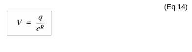](https://stanslegacy.com/uploads/images/gallery/2023-12/y0mkeGwuGl3kVn4p-image-1703232346301.png)The potential at a point to a **charge** (q) at a **distance** (R) in a medium whose **dielectric constant** is (e).
# Electrically Charged Water Molecule [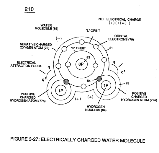](https://stanslegacy.com/uploads/images/gallery/2023-12/tgj1TAs4iQMFjqTd-image-1703376101819.png)Atomic structure of an **atom** (76) and (77) of Figure (3-27) exhibits two types of electrical charged mass entities, **orbital electrons** (79) having **negative electrical charges** ( - ) and a **nucleus** (84) (at least one proton) having a **positive electrical charge** ( + ). > The **positive electrical charge** of the nucleus equals the sum total of all **negative electrical charged electrons** when the atom is in "**stable-state**." In stable state or normal-state, the number of electrons equals the number of protons to give the atom "**no**" net electrical charge. ---Whenever one or more electrons are "**dislodged**" from the atom, the atom takes-on a net positive electrical charge and is called a **positive ion**.
If a electron combines with a stable or normal atom, the atom has a **net negative charge** and is called a **negative ion.****Voltage potential** (65) within electrical **circuit** (60) can cause one or more **electrons** (79) to be dislodged from the **water molecule atom** (85) of Figure (3-26) due to **opposite electrical polarity attraction** (qq') of Figure (3-29) between unlike charged entities, as shown in (160) of Figure (326) as to **Newton's** and **Coulomb's laws** of **electrical-force**.
| Figure (3-26) [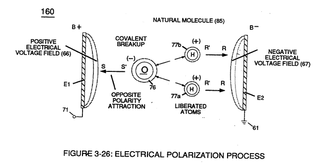](https://stanslegacy.com/uploads/images/gallery/2023-12/FI7iyHF5qFsbEw5X-image-1703376323691.png) | Figure (3-29) [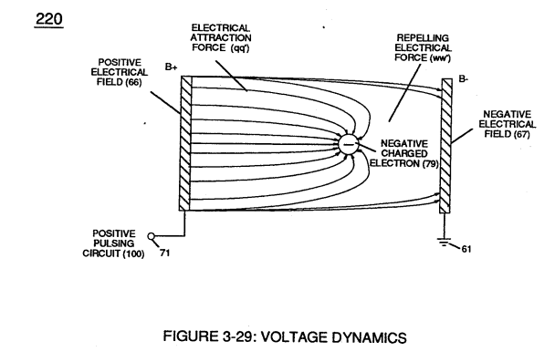](https://stanslegacy.com/uploads/images/gallery/2023-12/5AN8vz6fgBPasqR1-image-1703376333059.png) |
The resultant **electrical force** (qq') between the opposite electrical charged **hydrogen** (77) and **oxygen** (76) atoms keeps **water molecule** (210) intact when the **hydrogen atom** (77) shares its **electron** (84) with **oxygen atom** (76).
> The electrical strength of **attraction force** (qq') between the water molecule atoms is determined by the electrical size of the hydrogen atoms and the displacement of its **negative charged electrons** (84) during covalent sharing. [](https://stanslegacy.com/uploads/images/gallery/2023-12/tgj1TAs4iQMFjqTd-image-1703376101819.png)Oxygen atom becomes **negative electrical charged** (81) since **oxygen atom** (76), now, has a total of ten negative charged **electrons** (79a xxx 79n) in its "K" plus "L" orbits while maintaining it's original **eight positive charged protons** which makes up **oxygen nucleus** (83).Since the **hydrogen proton** (84) (hydrogen nucleus) remains (after covalent link up), then the **hydrogen atom** takes-on a **positive charge** (78) co-equalling the **positive charge** of the **hydrogen nucleus proton** (84).
Together, the total net charge of **water molecule** (85) is zero despite the fact that each water molecule atom retains its electrical charge.
In other words, water molecule (85) is a electrically bipolar molecule having a stable configuration of charged atoms bound together by **electrostatic force** (qq').Electromagnetic bonding forces between unlike **atoms** (76n7) are negligible or non-existence, since **oxygen atom** (76) electrons are paired together, while rotating in opposite direction which, in turn, causes **oxygen atom** (76) to be electromagnetically neutral to **hydrogen atom** (77).
> Electron theory of magnetism requires orbital electrons to spin in the same direction before an atom can exhibit a electromagnetic field.Furthermore, **external electrical force** (66/67) can alter the electromagnetic properties of a atom since electromagnetic force is dependent on the movement of **charged particles** in a electrostatic field **voltage Intensifier circuit** (190) of figure (3-23), now, allows voltage to dissociates **water molecule** (85) by overcoming **electrostatic bonding force** (qq') between **unlike atoms** (76n7) while restricting amp flow, as illustrated in (160) of Figure (3-26).
| Figure (3-23) [](https://stanslegacy.com/uploads/images/gallery/2023-12/7ffVlnHJcIOSoYRS-image-1703232587555.png) | Figure (3-26) [](https://stanslegacy.com/uploads/images/gallery/2023-12/FI7iyHF5qFsbEw5X-image-1703376323691.png) |
| Figure (3-29) [](https://stanslegacy.com/uploads/images/gallery/2023-12/5AN8vz6fgBPasqR1-image-1703376333059.png) | Figure (3-26) [](https://stanslegacy.com/uploads/images/gallery/2023-12/FI7iyHF5qFsbEw5X-image-1703376323691.png) |
| Figure (3-27) [](https://stanslegacy.com/uploads/images/gallery/2023-12/tgj1TAs4iQMFjqTd-image-1703376101819.png) | Figure (3-23) [](https://stanslegacy.com/uploads/images/gallery/2023-12/7ffVlnHJcIOSoYRS-image-1703232587555.png) |
Stationary "**positive**" electrical **voltage-field** (66) (*voltage plate E1*) not only attracts **negative charged oxygen atom** (76) but also pulls away **negative charged covalent electrons** (84) from **water molecule** (210).
[](https://stanslegacy.com/uploads/images/gallery/2023-12/FI7iyHF5qFsbEw5X-image-1703376323691.png)At the same time stationary "**negative**" **electrical voltage field** (67) (*voltage plate E2*) attracts **positive charged hydrogen atoms** (77a/b).Once **negative electrically charged oxygen atom** (76) is dislodged from **water molecule** (85), **covalent bonding** (*sharing electrons between atoms*) ceases to exist, switching-off and disrupting **electrical attraction force** (qq') between unlike atoms (76/77), as further illustrated in (160) of Figure (3-26).
**[](https://stanslegacy.com/uploads/images/gallery/2023-12/tgj1TAs4iQMFjqTd-image-1703376101819.png)Opposite polarity electrical attraction force** (SS') continues to cause **negative charged oxygen atom** (76) to migrate to **positive voltage-plate** (E1) (*positive voltage zone 66*); while, at the same time, **opposite polarity electrical attraction force** (RR') causes **positive charged hydrogen atoms** (77a/b) to migrate in the opposite direction to negative **voltage-plate** (E2) (*negative voltage zone 67*) as **step-charging voltage-wave** (65) increases in voltage amplitude from several millivolts to several hundred volts **during each pulse train** (65a xxx 65n) which, in application, causes **water molecule** (210) of Figure (3-27) charged atoms (76/77) to elongate (increasing distance between unlike atoms 76/77) to the point where **covalent hydrogen electrons** (84) of Figure (3-27) breaks away from **electrostatic force** (qq').Repetitive duplication of **voltage pulse** (65a xxx 65n) continues to separate or split apart other **water molecules** (85a xxx 85n) which, in turns, forms **hydrogen** (86) and **oxygen** (87) **gas-mixture** (88) of Figure (3-24).
Dissociation of **water molecule** (85) by way of **voltage stimulation** (65) is herein called "**The Electrical Polarization Process**", as illustrated in (160) of Figure (3-26).
| Figure (3-24) [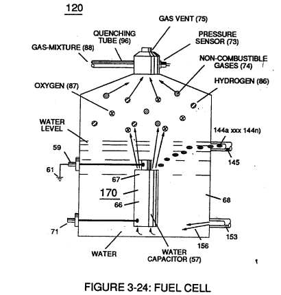](https://stanslegacy.com/uploads/images/gallery/2023-12/eS2UmsVf6o8YkE39-image-1703377231066.png) | Figure (3-26) [](https://stanslegacy.com/uploads/images/gallery/2023-12/FI7iyHF5qFsbEw5X-image-1703376323691.png) |
| Figure (3-30) [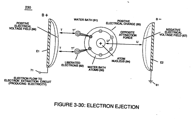](https://stanslegacy.com/uploads/images/gallery/2023-12/kRDULfVghXgQ3Mcm-image-1703377782828.png) | Figure (3-25) [](https://stanslegacy.com/uploads/images/gallery/2023-12/jmc1Z2WkjHNbWiZ6-image-1703201429384.png) |
Applied **electrical attraction force** (TT') and (UU') always being of **equal voltage intensity** but **opposite in electrical polarity** as **voltage amplitude** (65) is attenuated.
Replication of **higher voltage forces** (TT') and (UU') during pulsing operations causes a continued release of other **electrons** (92a xxx 92n) from other **water bath atoms** (93a xxx 93n) which, in practice, increases electrical charges of **water bath** (91) since **water bath** (91) is a dielectric liquid.
**[](https://stanslegacy.com/uploads/images/gallery/2023-12/jmc1Z2WkjHNbWiZ6-image-1703201429384.png)Water bath atoms** (93a xxx 93n) having missing **electrons** (92) take-on a **positive electrical charge** (95) which is subject to and moved by **negative electrical force** (UU'); whereby, the liberated and free floating **negative charge electrons** (92) are subject to and moved by **positive electrical force** (TT'). Applied together, **electrical forces** (TT') and (UU'), now, causes these moving electrically charged particles to superimpose a **physical impact** unto **electrical polarization process** (160), as shown in (170) of Figure (3-25)... thereby, increasing **gas-yield** (88) still further.
[](https://stanslegacy.com/uploads/images/gallery/2023-12/7ffVlnHJcIOSoYRS-image-1703232587555.png)By attenuating **voltage amplitude** (Vo xxx Yn) in conjunction with **pulse-width** (65a xxx 65n) allows **voltage intensifier circuit** (190) of Figure (3-23) to tune-in and match the resonant characteristics or resonant frequency of **water bath** (91) since **water bath** (91) always maintains its dielectric properties during pulsing operations.At resonance, **electrical polarization process** (160) interacts uniformly with liberated **charged particles** (92/95) of Figure (3-25) to obtain a even **higher gas-yield** (88) at **maximum voltage deflection** (xxx Vn).
[](https://stanslegacy.com/uploads/images/gallery/2023-12/jmc1Z2WkjHNbWiZ6-image-1703201429384.png)The **established resonant frequency** is most generally in the audio range from 1 kHz up to and beyond 10 kHz; and is dependent upon the amount of contaminants in **natural water**. Oscillating and superimposing **electrically charged particles** unto the **Electrical Polarization process** at a given pulse-frequency is, now, herein called "**Resonant Action**", as illustrated in (240) of Figure (3-25). To reach **maximum** **gas-yield** (88) **resonant cavity** (170) of Figure (3-25) is shaped into a **tubular structure** (typically 0.50 inch diameter tube inserted into 0.75 inch diameter tube having a .0625 concentric air-gap 3 inches long) which functions as a longitudinal wave-guide to enhance particle movement in a lateral or angular displacement to applied voltage fields (66/67). **Insulated housing** (72) prevents **voltage coupling to water bath** (68) which allows **applied voltage amplitude** (xxx Vn) to remain constant across **water molecules** (85a xxx 85n)... stabilizing gas production during voltage stimulation (65), as shown in (120) of Figure (3-24).
[](https://stanslegacy.com/uploads/images/gallery/2023-12/eS2UmsVf6o8YkE39-image-1703377231066.png)To further prevent voltage fluctuation during resonant action, **Phase Lock Loop** technique of **Pulse Indicator circuit** (110) is utilized during pulsing operations.
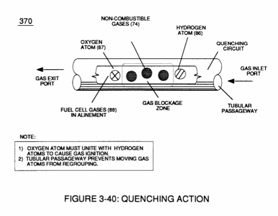
The resultant **fuel-gas** (88) is, now, transferred through **Quenching Tube** (96) of Figure (3-41) to, through and beyond **Fuel Injectors** (36) of Figure (3-1) for Hydrogen gas utilization. [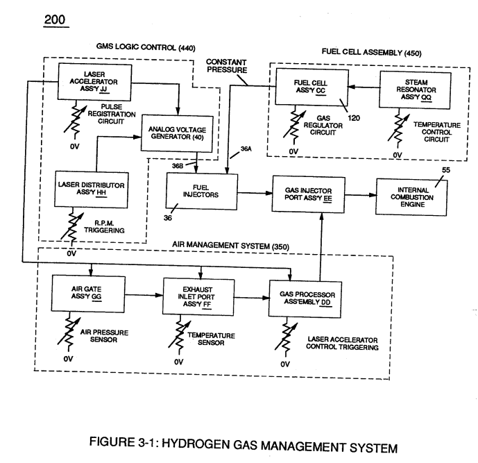](https://stanslegacy.com/uploads/images/gallery/2023-12/oLcI6QctvGXUJUGz-image-1703378297056.png)In cases where applied voltage amplitude is to remain constant while promoting **Resonant Action** during control-state, **incoming pulse train** (64a xxx 64n) is varied independent of voltage amplitude to attenuate **voltage intensity** (66/67) which, in turn, effects gas production.In other applications, **Voltage amplitude** (66/67) in direct relationship to **pulse-train** (64a xxx 64n) may be varied together in a progressive manner to further control gas production. Or pulse-train (64a xxx 64n) can remain constant while voltage amplitude is varied.
In all cases, **Resonant Action** is being promoted to produce hydrogen gas on demand.
In terms of Longevity, **voltage zones** (E1/E2) are composed of or made of stainless steel T304 material which is chemically inert to hydrogen, oxygen, and ambient air gases (*dissolved gases in water*) being liberated from **water bath** (68) during **voltage stimulation** (65). > Under actual certified laboratory testing stainless steel T304 life expectancy (*material decomposition*) is .0001 per year since **voltage** (65) is a physical force, setting up a non-chemical environment since amps consumption is being restricted to a minimum and "no" electrolyte is added to **water bath** (68).In practice, **stainless steel voltage plates** (E1/E2) physically forms **voltage zones** (66/67) regardless of geometric shape or configuration of **resonant cavity** (170).
Under normal gas ignition or gas combustion process, released **Fuel-Gases** (88) of Figure (3-39) as to Figure (3-24) nets a **thermal explosive energy yield** (gtnt) of approximately 2 1/2 rimes greater than gasoline.| Figure (3-39) [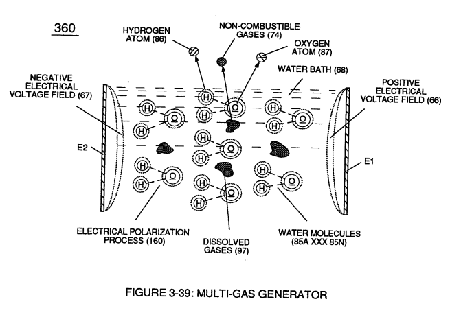](https://stanslegacy.com/uploads/images/gallery/2023-12/DapPTPnafhxr0u3b-image-1703378524117.png) | Figure (3-24) [](https://stanslegacy.com/uploads/images/gallery/2023-12/eS2UmsVf6o8YkE39-image-1703377231066.png) |
| **Dissolved air gases** (97) of Figure (3-39) [](https://stanslegacy.com/uploads/images/gallery/2023-12/DapPTPnafhxr0u3b-image-1703378524117.png) | **Electrical Polarization Process** (160) of Figure (3-26) [](https://stanslegacy.com/uploads/images/gallery/2023-12/FI7iyHF5qFsbEw5X-image-1703376323691.png) |
| **Fuel-Gas mixture** (88) of Figure (3-24) [](https://stanslegacy.com/uploads/images/gallery/2023-12/eS2UmsVf6o8YkE39-image-1703377231066.png) | (330) of Figure (3-37) [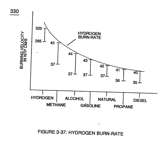](https://stanslegacy.com/uploads/images/gallery/2023-12/WlQY61kCMBoWAmvg-image-1703378872882.png) |
| (320) of Figure (3-36) [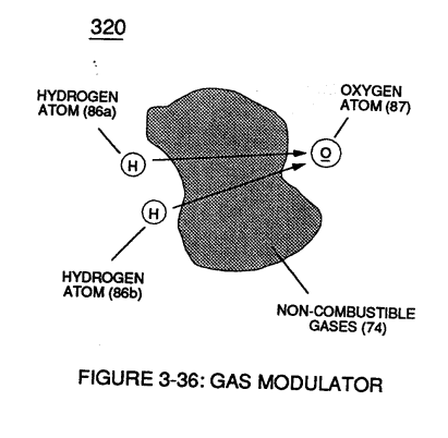](https://stanslegacy.com/uploads/images/gallery/2023-12/rtVP70fKKJltrRpY-image-1703269420703.png) | Figure (3-39) [](https://stanslegacy.com/uploads/images/gallery/2023-12/DapPTPnafhxr0u3b-image-1703378524117.png) |
| (340) of Figure (3-38) [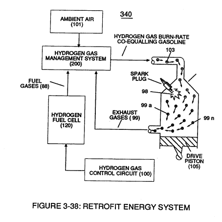](https://stanslegacy.com/uploads/images/gallery/2023-12/MeLbNiqN8Ishsstr-image-1703379003610.png) | Figure (3-24) [](https://stanslegacy.com/uploads/images/gallery/2023-12/eS2UmsVf6o8YkE39-image-1703377231066.png) |
**Water bath** (68) of Figure (3-39) as to Figure (3-24), now, becomes and functions as a "**Gas Mixing Regulator**" since the highest possible **thermal explosive energy yield** (gtnt) obtainable from hydrogen during "normal" **gas ignition** (98) is the exact composition of water where **two hydrogen atoms** (86a / 86b) unite with **oxygen atom** (87).
[](https://stanslegacy.com/uploads/images/gallery/2023-12/FI7iyHF5qFsbEw5X-image-1703376323691.png)Inherently, the utilization of the **Electrical Polarization Process** (160) of Figure (3-26) in conjunction with the use of chemically inert stainless steel (T304 material) **voltage zones** (E1 / E2) submerged in **natural water** (68) sustains and maintains **gas mixing ratio** (88) by simply preventing the consumption of both the **hydrogen** (86) and **oxygen** (87) gases by way of not encouraging "electrical heat" or "chemical interaction" associated with amp consumption.Remember, **Electrical Polarization Process** (160) is a physical process which uses **opposite electrical polarity attraction force** (qq') to perform work by disrupting and switching off the covalent bond between the unlike charged water molecule atoms.
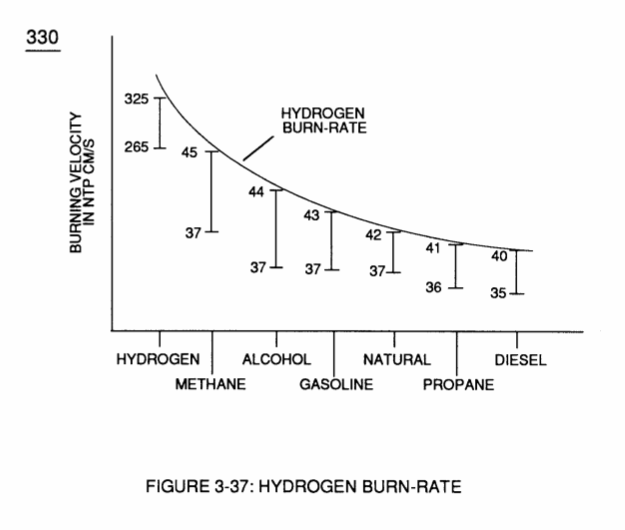
To further reduce **hydrogen burn-rate** (330) of Figure (3-37) to other fossil-fuel burning levels, additional **non-combustible gases** (99a xxx 99n) (*supplied via ambient air 101*) is added to **gas-mixture** (88) by way of **gas ignition process** (98) occurring inside **internal combustion engine** (55) **piston cylinder** (102), as illustrated in (340) of Figure (3-38).
| **hydrogen burn-rate** (330) of Figure (3-37) [](https://stanslegacy.com/uploads/images/gallery/2023-12/WlQY61kCMBoWAmvg-image-1703378872882.png) | (340) of Figure (3-38) [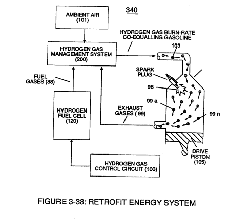](https://stanslegacy.com/uploads/images/gallery/2023-12/hCQI9T9DxApWIQWc-image-1703231476158.png) |
... releasing **thermal explosive energy** (gtnt) which, in turns, causes piston-action to expel the newly formed **non-combustible exhaust gases** (99) for recycling.
The liberated and cooled **exhaust gases** (99) is, now, directed to **hydrogen injector system** (200) which systematically meter-mixes and superimposes a predetermined amount of **non-burnable gases** (99) of Figure (3-38) onto incoming **ambient air gases** (101) which is being directed to **engine cylinder** (102) to sustain and maintain both the "**Gas Modulator Process**" (320) of Figure (3-36) and the "**Gas Ignition Process**" (98), simultaneously.
| "**Gas Modulator Process**" (320) of Figure (3-36) [](https://stanslegacy.com/uploads/images/gallery/2023-12/rtVP70fKKJltrRpY-image-1703269420703.png) | (340) of Figure (3-38) [](https://stanslegacy.com/uploads/images/gallery/2023-12/hCQI9T9DxApWIQWc-image-1703231476158.png) |
In essence, then, **ambient air gases** (101) becomes an endless supply of **non-combustible gases** (99A xxx 99n) during the gas ignition process.
The resultant and on-going **Gas Modulator Process** (320) of Figure (3-36), now, allows **hydrogen fuel cell** (120) of Figure (3-24) to be retrofitted to any conventional **internal combustion engine** (55) of Figure (3-1) without engine change by simply metering the proper amount of **exhaust gases** (99a xxx 99n) to comply with and co-equaling any type or different fossil-fuel burning levels, as further illustrated in (330) of Figure (3-37).| **Fuel-Gas mixture** (88) of Figure (3-24) [](https://stanslegacy.com/uploads/images/gallery/2023-12/eS2UmsVf6o8YkE39-image-1703377231066.png) | (330) of Figure (3-37) [](https://stanslegacy.com/uploads/images/gallery/2023-12/WlQY61kCMBoWAmvg-image-1703378872882.png) |
In terms of operability and performance, **gas modulator** **process** (320) continues to allow a conventional **internal combustion engine** (55) to run on ambient air gases; while, **fuel-gas** (88) not only cuts back and reduces oxygen extraction form ambient air (101) but produces a environmentally safe exhaust gases since **non-combustible gases** (99/74) from both **ambient air gases** (101) and **Fuel-Gas** (88) are thermally inert to **gas ignition process** (98).
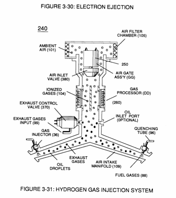
# Gas Processor To obtain higher energy-yields beyond the normal gas combustion process, **ionized ambient air gases** (104) of Figure (3-31) is, now, exposed to and intermixed with **Fuel-Gases** (88) prior to **thermal gas ignition** (98) of Figure (3-38), as illustrated in (240) of Figure (3-31).| Figure (3-31)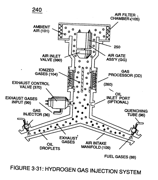 | Figure (3-38) [](https://stanslegacy.com/uploads/images/gallery/2023-12/hCQI9T9DxApWIQWc-image-1703231476158.png) |
...opposite **electrical attraction forces** (xx') and (yy') being of equal intensity, as further illustrated in (260) of Figure (3-33).
Once electron ejection occurs, the liberated and free floating **electrons** (117a xxx 117n) continue to migrate toward **positive voltage zone** (106); whereas, the newly formed **ionized gas atom** (*having missing electrons*) (104) continues to move onward and through **air intake manifold** (109) of Figure (3-31) to **engine cylinder** (102) of Figure (3-38).
| **air intake manifold** (109) of Figure (3-31) [](https://stanslegacy.com/uploads/images/gallery/2023-12/BEpqogfwYffUI6y9-image-1703268011715.png) | **engine cylinder** (102) of Figure (3-38) [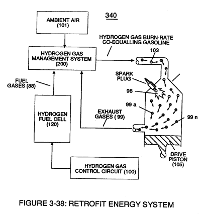](https://stanslegacy.com/uploads/images/gallery/2023-12/yB8tZ6LqeFmcYRcU-image-1703230122079.png) |
| **Electron Extraction Circuit** (270) of Figure (3-34) [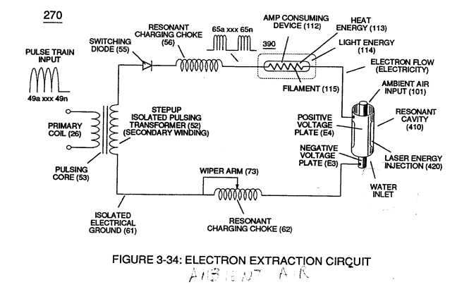](https://stanslegacy.com/uploads/images/gallery/2023-12/bU3ziUnuN8oEc6BH-image-1703379867341.png) | **Voltage Intensifier Circuit** (60) of Figure (3-22) [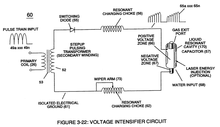](https://stanslegacy.com/uploads/images/gallery/2023-12/ac0BtQ09MXEOZruA-image-1703379886022.png) |
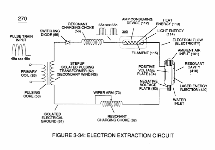
Repetitive formation of electrical voltage force or **voltage intensity** (65a xxx 65n) of Figure (3-21) attracts and causes **liberated electrons** (117a,xxx 117n) to move electrically away from **gas resonant cavity** (410) and physically interact with **light bulb filament** (115) to initiate and perform **kinetic conversion process** (390), as further illustrated in (270) of Figure (3-34).
| **voltage intensity** (65a xxx 65n) of Figure (3-21) [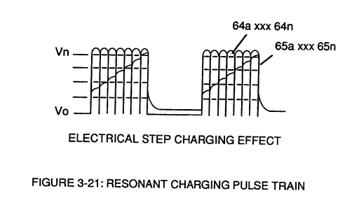](https://stanslegacy.com/uploads/images/gallery/2023-12/2lqF1gDBpLmvgIK1-image-1703379995321.png) | **kinetic conversion process** (390) as to (270) of Figure (3-34) [](https://stanslegacy.com/uploads/images/gallery/2023-12/bU3ziUnuN8oEc6BH-image-1703379867341.png) |
The newly established and on-going **electron conversion process** (390) continues to aid **ionized gas process** (260) as other **gas atoms** (101a xxx 101n) are destabilized into **ionized gas vapor** (104a xxx 104n).
The **electron conversion process** (390) is, of course, terminated when applied pulse **voltage potential** (65) is switched off. Pulsating voltage potential or **voltage intensity** (65a xx 65n) is adjusted, also, to "tune-in" to the resonant properties of **ambient air gases** (101) since **ambient air gases** (101) exhibits a dielectric value (air-gap of one inch resisting electron arc-over of up to 17,000 volts applied) between **voltage plates** (E3) and (E4), forming **capacitor** (410) of Figure (3-34). **Voltage fields** (106/107) are physically configured (*skin effect*) by T304 stainless steel material to form **voltage plates** (E3/E4) of Figure (3-33) which are not only chemically inert to **gas ionization process** (260) but, also, forms tubular **Gas Resonant Cavity** (410) of Figure (3-34) having approximately the same size and shape of **liquid resonant cavity** (170) of Figure (3-25), as illustrated in (270) of Figure (3-34).| **liquid resonant cavity** (170) of Figure (3-25) [](https://stanslegacy.com/uploads/images/gallery/2023-12/jmc1Z2WkjHNbWiZ6-image-1703201429384.png) | (270) of Figure (3-34). [](https://stanslegacy.com/uploads/images/gallery/2023-12/bU3ziUnuN8oEc6BH-image-1703379867341.png) |
| Figure (3-33) 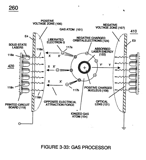 | (270) of Figure (3-34) [](https://stanslegacy.com/uploads/images/gallery/2023-12/bU3ziUnuN8oEc6BH-image-1703379867341.png) |
The absorbed **laser energy** (122) of Figure (3-35) not only causes ionized **gas atom orbital electrons** (124) to be deflected away from **gas atom nucleus** (108) but, also, weakens **electrostatic force** (AA') between **gas atom nucleus** (108) and deflecting **electrons** (123a xxx)
... allowing even a greater number of electrons (117a xxx) to be ejected from ionized gas atom (104) being simultaneously subjected to Electron Extraction Process (260), as illustrated in (280) of Figure (3-35).
[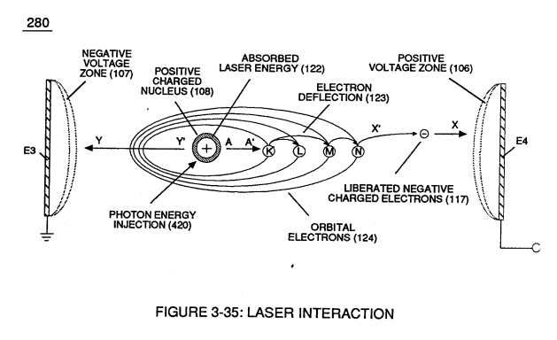](https://stanslegacy.com/uploads/images/gallery/2023-12/jglJdXxetuZ7I3mi-image-1703380690802.png)In essence, then, **laser interaction** (280) along with applied **voltage process** (260) causes **gas atom** (101) to go into sub-critical state (*destabilizing the mass entity of a gas atom) since absorbed laser energy (122) prevents electrons re-capture (atoms accepting electrons*) while **interfacing circuit** (270) dislodges, captures, and immediately consumes **ejected electrons** (117a xxx) In other words, **ambient air gases** (101) has, now, become **electromagnetically primed destabilized gas atoms** (l04a xxx 100n) having missing electrons.
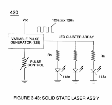
**Solid state light-emitting diode** (118) of Figure (3-33) arranged in a **cluster-array** (118a xxx 118n) mounted on **printed circuit board** (119) emits a discrete wave-length of light energy (*electromagnetic energy*) when **light circuit assembly** (420) of Figure (3-43) is **electrically pulsed** (126a xxx 126n) via **variable pulsing circuit** (125) in such a way as to vary **light intensity** (116) to match the light absorption rate of **ionized gas** (104), and, is determined with respect to the forward current through Led's (118) by (Eq 15) [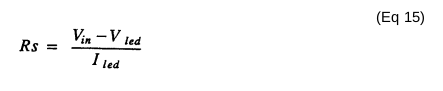](https://stanslegacy.com/uploads/images/gallery/2023-12/bGtrt6OAbopr6IC3-image-1703380798742.png) Where I led, is the specified forward current (typically 20ma per diode); V led is the led voltage drop (typically 1.7 volts for red emitter's).**Ohm's law** for **led circuit** in **parallel array**, and, is given by (Eq 16)
[](https://stanslegacy.com/uploads/images/gallery/2023-12/JVUBKdVH8zzGR1s7-image-1703380895060.png) Where > It is the forward current through led cluster-array; Vcc is volts applied (typically 5 volts) WherebyLaser or light intensity is variable as to duty cycle on/off pulse frequency from 1hz up to and beyond 10khz, and is given by (Eq 17)
> Le is light intensity in watts; Tl is current on-time; 1'2 is current off-time; and (ION) = RMS value of > load current during on-period. [](https://stanslegacy.com/uploads/images/gallery/2023-12/BEpqogfwYffUI6y9-image-1703268011715.png)[](https://stanslegacy.com/uploads/images/gallery/2023-12/lHP94H3qrhSf1jnp-image-1703380915073.png) In terms of assembly, **gas resonant cavity** (410), **electron extraction circuit** (270), **optical lens** (121) forms **gas processor** (260) of Figure (3-31).In retrospect to operational parameters, led's (118) light spectrum (*extending from the visible into the Ultraviolet light region*) can be selected for a given or predetermined **electromagnetically** **gas priming application** (280) since **gas nucleus** (108) is more responsive to coherent rather than diffused light source.
[](https://stanslegacy.com/uploads/images/gallery/2023-12/jglJdXxetuZ7I3mi-image-1703380690802.png)Applied **voltage amplitude** (Va xxx Vn), applied voltage **pulse frequency** (65a xxx 65n), and applied **current pulse train** (126a xxx 126n) are design variable to "tune-in" to the resonant properties of **gas atom** (101) while stimulating and performing **gas process** (260) which attenuates **electrical force** (AA') of Figure (3-35) to disrupt the mass equilibrium of **gas atom** (104).The resultant and newly formed **sub-critical gas atoms** (104a xxx 104n) are directed onward through **air intake manifold** (109) of Figure (3-31) to and beyond both **exhaust gas metering port** (370) and **injector port** (36) where **metered fuel-gas** (88), **metered exhaust gases** (99), and **metered sub-critical gas atoms** (104a xxx 104n) forms **gas-mixture** (103) entering **engine cylinder** (102), as illustrated in (240) of Figure (3-31) as to (340) of Figure (3-38).
| (240) of Figure (3-31) [](https://stanslegacy.com/uploads/images/gallery/2023-12/RZgv6N5lO3RYvQVg-image-1703267421175.png) | (340) of Figure (3-38) [](https://stanslegacy.com/uploads/images/gallery/2023-12/hCQI9T9DxApWIQWc-image-1703231476158.png) |
**Sub-critical Oxygen atom** (129) having less than the normal amount of **covalent electrons** (orbital electrons) is unable to reach "stable-state" (*six to eight covalent electrons required*) when the two **hydrogen atoms** (128 a/b) seek to form the water molecule during thermal gas ignition.
**Absorbed laser energy** (131) of **hydrogen gas atom nucleus** (133) weakens **"electrical bonding" force** (CC') between **hydrogen atom electron** (132) and **hydrogen atom nucleus** (133);
while, at the same time, **absorbed laser energy** (135) prevents **oxygen atom** (129) from reaching "stable state" when **electrical attraction force** (BB') (opposite electrical attraction force being equivalent to the number of missing electrons) locks onto and pulls away **hydrogen atom electron** (132) while **repelling force** (DD') keeps the two **positive charged nucleus's** (133/136) apart.
[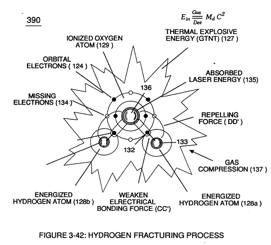](https://stanslegacy.com/uploads/images/gallery/2023-12/kfEIJ9oXKSQGdG0T-image-1703231970050.png)These "'**abnormal**" and "**unstable**" conditions coupled with **thermal interaction** (gas ignition) under **gas compression** (137) of Figure (3-42) as to Figure (3-38) (*fuel-gas 88 being compressed via piston-action 105*) causes **combustible gas atoms** (129 and 128a/b) to decay ... releasing **thermal explosive energy** (gtnt) (127) under control means.This atomic thermal-interaction between sub-critical **combustible gas atoms** (127 and 128a/b) is, now, herein after called "**The Hydrogen fracturing Process**. "
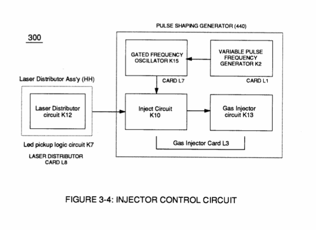
# Laser Distributor [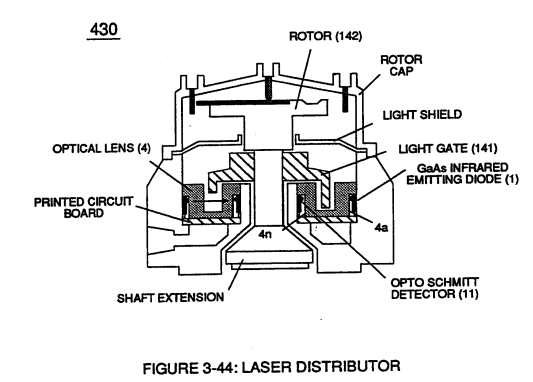](https://stanslegacy.com/uploads/images/gallery/2023-12/fwlFaeAo0Kc4kiVD-image-1703231376468.png)**Laser Distributor assembly** (430) of Figure (3-44) functions in similar manner as **Laser Accelerator** (20) of Figure (3-10) except **light-gate** (141) of Figure (3-44) rotates in the same direction of **Spark-rotor** (142) and being displaced opposite to **rotor blade** (142), allowing intermixed **processed ambient air gases** (101) and **Fuel-Gases** (88) to enter **engine cylinder** (102) of Figure (3-38), as illustrated in **Injector Control Circuit** (300) of Figure (3-4).| **Laser Accelerator** (20) of Figure (3-10) [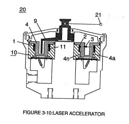](https://stanslegacy.com/uploads/images/gallery/2023-12/HDLNOmyyxVbMa7Qq-image-1703231512088.png) | **engine cylinder** (102) of Figure (3-38) [](https://stanslegacy.com/uploads/images/gallery/2023-12/Q4iFEAzuA1BR3it4-image-1703231477742.png) |
| Figure (3-1) [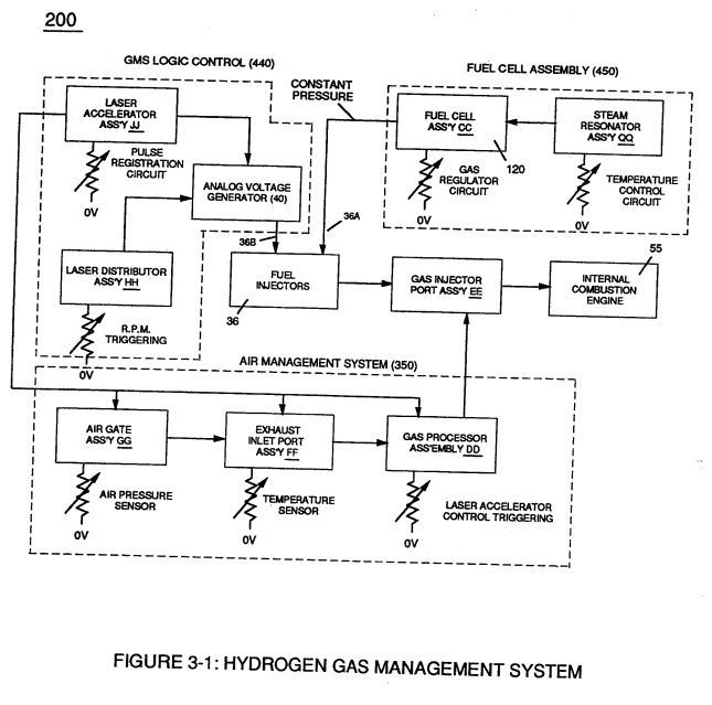](https://stanslegacy.com/uploads/images/gallery/2023-12/63xXWMI18EUm751n-image-1703231251786.png) | Figure (3-4) [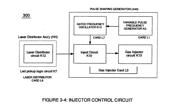](https://stanslegacy.com/uploads/images/gallery/2023-12/whRKNV0TsUvGIS1d-image-1703231300544.png) |
Interlocking **Laser Accelerator output** {JJ) with **Laser Distributor output** (HH) of Figure (3-1) causes **Fuel-Injectors** (36) to be "Tuned" with both **Air Management System** (350) of Figure (3-2) and **Hydrogen Gas Control Circuit** (100) of Figure (3-5) to maintain constant **Fuel-mixing Ratio** (290) of Figure (3-3) during engine performance.
| Figure (3-2) [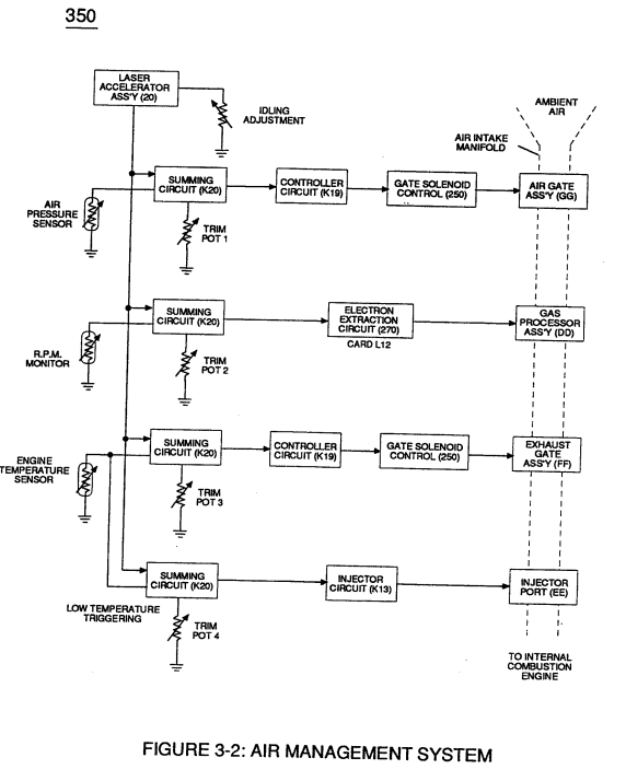](https://stanslegacy.com/uploads/images/gallery/2023-12/XO2etRCiPJqXwH8O-image-1703231274750.png) | Figure (3-5) [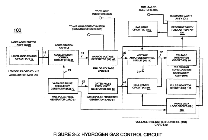](https://stanslegacy.com/uploads/images/gallery/2023-12/6PSO3ExpRKOuqNXU-image-1703231313963.png) |
Opposite or reverse movement of **Laser Accelerator** (JI) decreases **Injectors** (36) **on-time** which, in turns, reduces engine speed.
# Impurity Extraction Process [](https://stanslegacy.com/uploads/images/gallery/2023-12/SfsY9Ms8MRP5eM0o-image-1703197304479.png)Suspended and dissolved **water contaminates** (144a xxx 144n) (*typically 20 ppm to 40 ppm in natural water*) of Figure (3-24) being uniformly released from and superimposed onto remaining **water bath** (68) during **Resonant Action** (170) are directed to and passes through **water inlet line** (145) ... causing liberated, moving, and free-floating **micro-sized contaminates** (144a xxx 144n) to be deposited inside **Electrostatic Filter Assembly** (440) and subsequently exposed to **opposite electrical voltage fields** (148/152), as so illustrated in Figure (3-45). **Negative electrically charged contaminates** (157a xxx 157n) migrates to and entrapped by **positive electrical voltage post** (147); while, simultaneously, **positive electrical charged contaminates** (158a xxx 158n) are attracted to and entrapped by **negative electrical voltage post** (151) ... thereby, extracting **contaminates** (144a xxx 144n) from **water bath** (68) [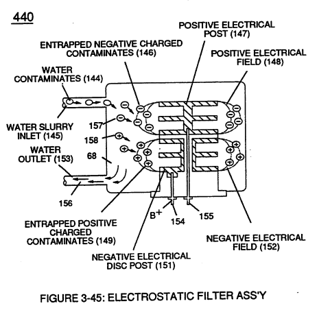](https://stanslegacy.com/uploads/images/gallery/2023-12/J8m3rwK9yPS8xvgK-image-1703230325676.png) ... producing **purified water bath** (156) which is recycled back into **Fuel Cell** (120) of Figure (3-24) since **Resonant Action** (170) also function as and performs as a **water-pump** (Gas rising). Exposing **water contaminates** (144a xxx 144n) to **applied voltage fields** (E1/E2) not only produces **electrical charged contaminates** (157/158); but, also, kills bacteria that might be present in **water bath** (68).Periodically **back-flushing** (rinsing out) is all that is required to ensure and sustain **Electrostatic Filter Process** (440).
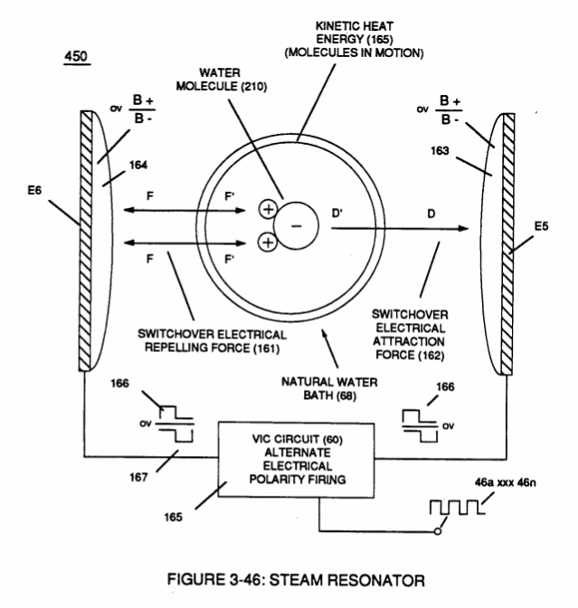
# Steam Resonator To further ensure proper **Fuel Cell** optional performance during frigid or below freezing weather conditions, **Steam Resonator** assembly (450) of Figure (3-46) is inserted into **Fuel Cell** (120) of Figure (3-24) and thermostatically activated via **Voltage Intensifier Circuit** (165) which directly applies an **alternate** or **opposite** (166/167) **electrical voltage pulses** *(during amp restriction)* in a sequential manner across **voltage plates** E5/E6.Once positive energized, **water molecule** (210) of **water bath** (68) is deflected toward **voltage surface** (E5) via both **opposite electrical attraction force** (162) and **electrical repelling force** (161).
| Figure (3-46)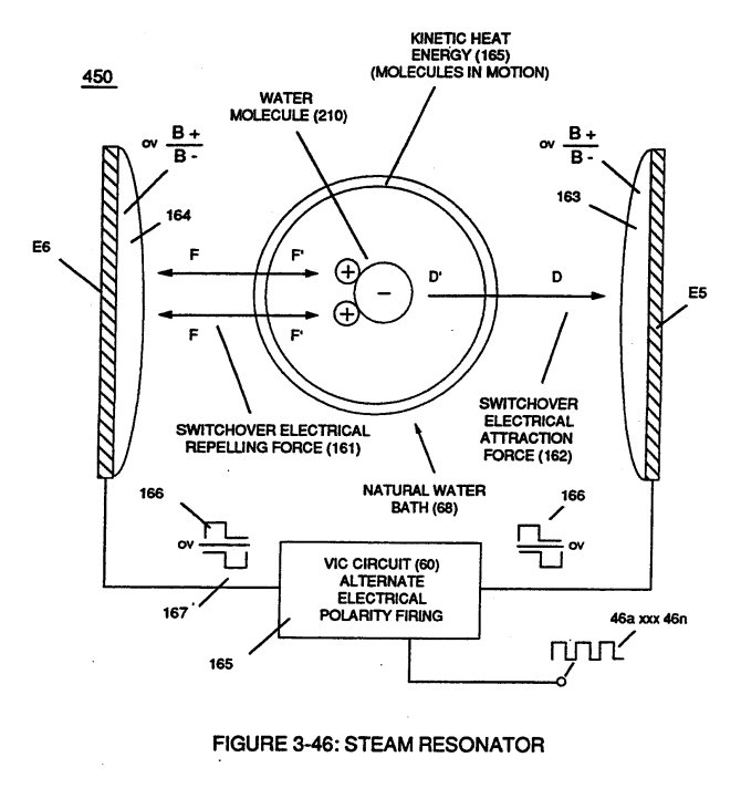 | Figure (3-24) |
... producing **kinetic energy** (165) (*particle impact*) which, in turns, heats **water bath** (68).
Repetitive formation of **opposite voltage pulses** (166/167) at a given pulse-frequency continues to **heat water bath** (68) until a desired temperature is reached.
# Diesel Application By simply adjusting **Fuel-**gases (88) of figure (3-38) **burn-rate** (330) of Figure (3-37) from (43 - 37 cm/s) (Gasoline) to (40 - 35 cm/s) (Diesel) burning levels, now, allows **WFC Hydrogen Gas Management System** to be directly retrofitted to conventional **Diesel Engines** since the newly established modulated **Hydrogen Fuel-mixture** (88 - Diesel) co-equals **spark-ignition ratio** (typically .35 -.39 ) of standard **Diesel-Fuel** (Fossil) under compression.| **Fuel-**gases (88) of figure (3-38) [](https://stanslegacy.com/uploads/images/gallery/2023-12/yB8tZ6LqeFmcYRcU-image-1703230122079.png) | **burn-rate** (330) of Figure (3-37) [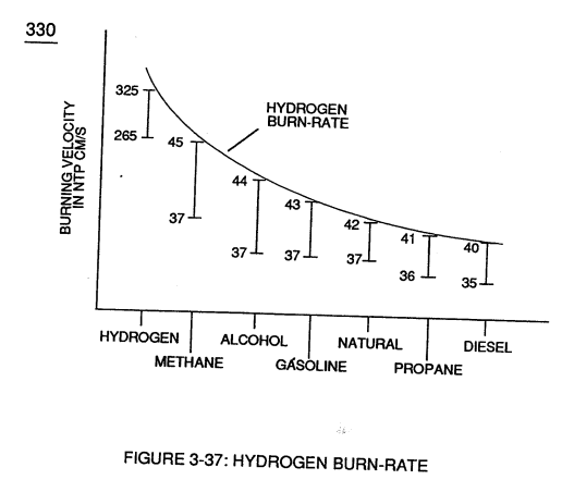](https://stanslegacy.com/uploads/images/gallery/2023-12/CbESYYgb8Xk9jTAc-image-1703230131735.png) |
| Figure (4-11) [](https://stanslegacy.com/uploads/images/gallery/2023-12/pufFIZsDzESvnoJ6-image-1703206086002.png) | Figure (4-14) [](https://stanslegacy.com/uploads/images/gallery/2023-12/7k3oaVVI5k4h3tMX-image-1703206095624.png) |
| **Hydrogen Fuel-Gas Assembly** (450) of Figure (3-1) [](https://stanslegacy.com/uploads/images/gallery/2023-12/bwyleZKqXz2LbuMC-image-1703229950405.png) | **Water Fuel Injector Assembly** (10) of Figure (4-1) [](https://stanslegacy.com/uploads/images/gallery/2023-12/cnI9GgSoTbKZ8DWk-image-1703046505270.png) |
It's design concept and system application complies with the "laws of economics" since micro-chip electronics and plastic mold injection technology help ensure performance reliability and usage
... especially since **Fuel Cell** (120) of Figure (3-24) is miniaturized to **Water Fuel Injector Plug** (40) of Figure (4-2), as further illustrated in [WFC memo 423 DA](https://stanslegacy.com/books/the-birth-of-new-technology/chapter/wfc-423da-water-fuel-injection-system "WFC 423DA - Water Fuel Injection System").| **Fuel Cell** (120) of Figure (3-24) [](https://stanslegacy.com/uploads/images/gallery/2023-12/VC05uhRvsvknmnD8-image-1703229883654.png) | **Water Fuel Injector Plug** (40) of Figure (4-2) [](https://stanslegacy.com/uploads/images/gallery/2023-12/ktSAtfSopo6pX4ES-image-1703229856171.png) |
| [](http://stanslegacy.com/uploads/images/gallery/2022-06/87fqMev15vKpDA21-image-1656378349303-05-47.png) | [](http://stanslegacy.com/uploads/images/gallery/2022-06/qfqKBWQkpTLBpmmK-image-1656378498842-08-16.png) | [](http://stanslegacy.com/uploads/images/gallery/2022-06/Yi4p2cQHeO4zwIrx-image-1656378509671-08-26.png) |
| [](http://stanslegacy.com/uploads/images/gallery/2022-06/wt3G2yMaDSOSlHhh-image-1656378518977-08-36.png) | [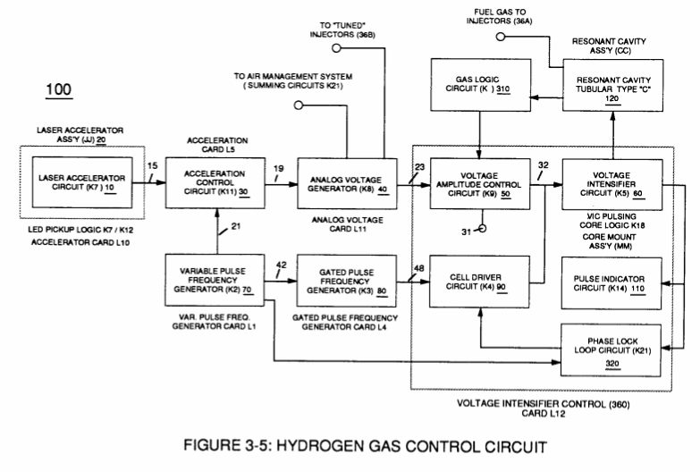](http://stanslegacy.com/uploads/images/gallery/2022-06/ciXweCN1saeyY6Jf-image-1656378530989-08-47.png) | [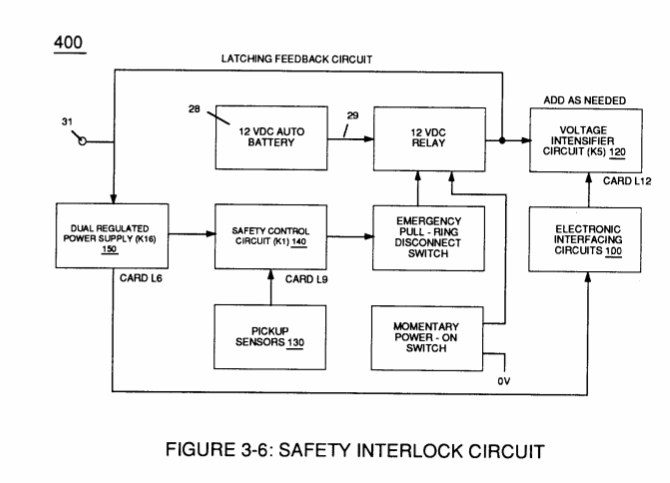](http://stanslegacy.com/uploads/images/gallery/2022-06/7Yh9PGWmrVCafO62-image-1656378542096-08-59.png) |
| [](http://stanslegacy.com/uploads/images/gallery/2022-06/5lcNPdzwhdvy87Fi-image-1656378552120-09-08.png) | [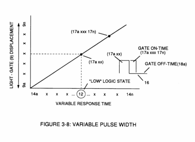](http://stanslegacy.com/uploads/images/gallery/2022-06/3T7FoNgVzyF9dFjB-image-1656378559066-09-16.png) | [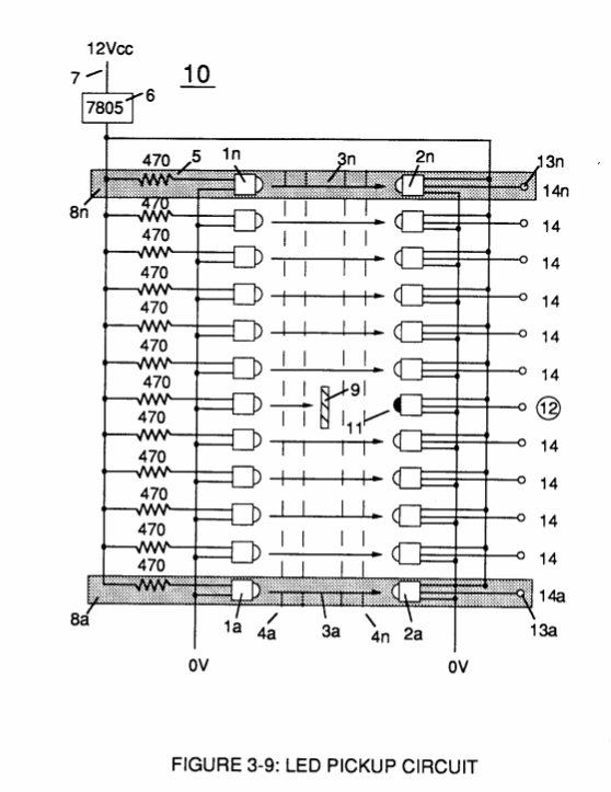](http://stanslegacy.com/uploads/images/gallery/2022-06/fZhMpjE7sz73D5Em-image-1656378566339-09-24.png) |
| [](http://stanslegacy.com/uploads/images/gallery/2022-06/VnqfbBE759hYMtOx-image-1656378574809-09-32.png) | [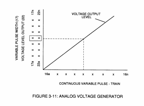](http://stanslegacy.com/uploads/images/gallery/2022-06/81Jkh3kQ8mx0CvB4-image-1656378580364-09-38.png) | [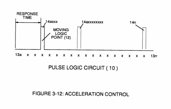](http://stanslegacy.com/uploads/images/gallery/2022-06/xjUcU1BN8HFS8VKT-image-1656378587465-09-45.png) |
| [](http://stanslegacy.com/uploads/images/gallery/2022-06/bnGzN1OQXnaPIQMU-image-1656378594474-09-52.png) | [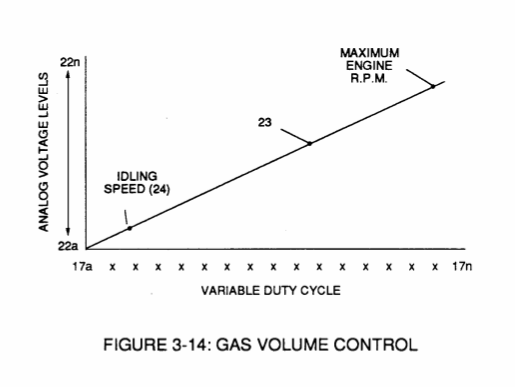](http://stanslegacy.com/uploads/images/gallery/2022-06/5Chkdi1v5hD6SiH3-image-1656378601505-09-59.png) | [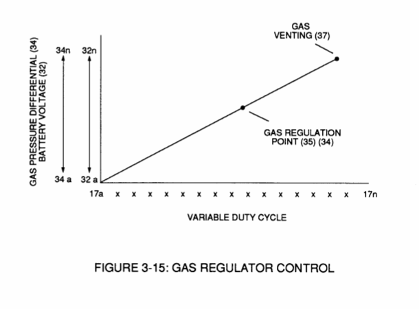](http://stanslegacy.com/uploads/images/gallery/2022-06/w5KAe8p56WdbDqtb-image-1656378606856-10-05.png) |
| [](http://stanslegacy.com/uploads/images/gallery/2022-06/9ATAcq0QG8GIMGmE-image-1656378620460-10-18.png) | [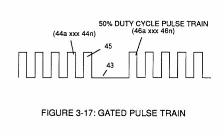](http://stanslegacy.com/uploads/images/gallery/2022-06/rYMCR1NM5GAhVaJh-image-1656378626355-10-24.png) | [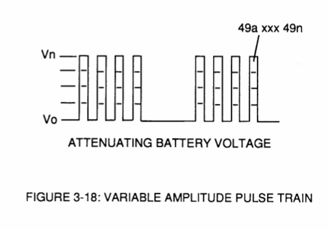](http://stanslegacy.com/uploads/images/gallery/2022-06/cCgAB8tyIHkMSrGS-image-1656378632089-10-30.png) |
| [](http://stanslegacy.com/uploads/images/gallery/2022-06/tohHqLQZYUyFk3bW-image-1656378640565-10-36.png) | [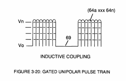](http://stanslegacy.com/uploads/images/gallery/2022-06/H43aHm1mhovBBSEL-image-1656378646994-10-45.png) | [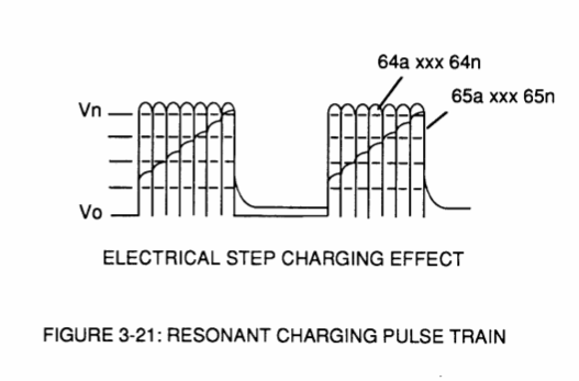](http://stanslegacy.com/uploads/images/gallery/2022-06/a2dCeo6LeefTyPSc-image-1656378654414-10-52.png) |
| [](http://stanslegacy.com/uploads/images/gallery/2022-06/Ltiiru0cIDbWw2FP-image-1656378664765-11-01.png) | [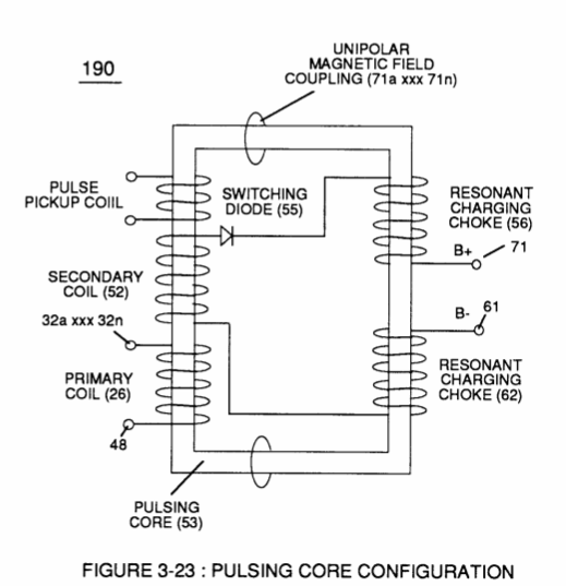](http://stanslegacy.com/uploads/images/gallery/2022-06/U0TD473TnYy7pkMK-image-1656378674398-11-12.png) | [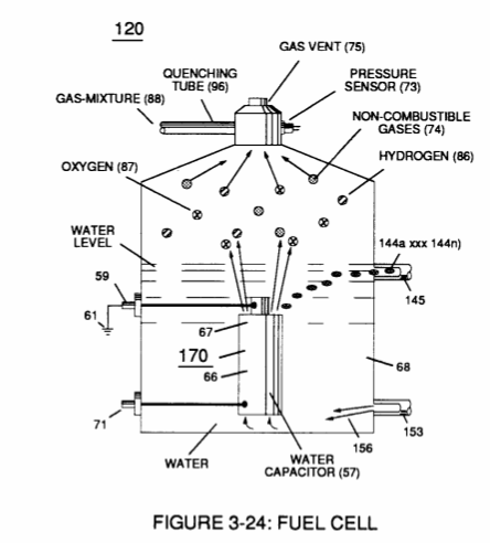](http://stanslegacy.com/uploads/images/gallery/2022-06/JfQPGJZpJNnAck2V-image-1656378682902-11-20.png) |
| [](http://stanslegacy.com/uploads/images/gallery/2022-06/VUAOMdsaH8rq0a3z-image-1656378693467-11-31.png) | [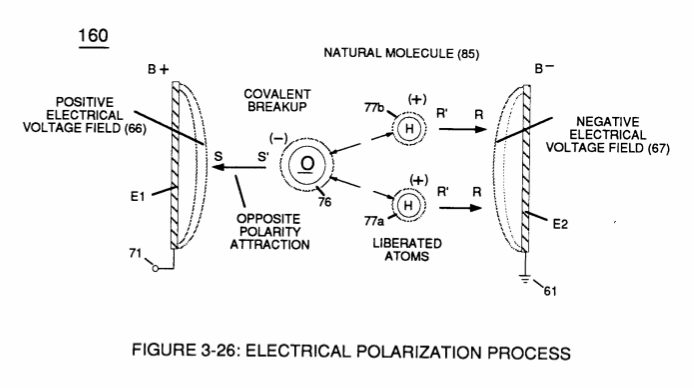](http://stanslegacy.com/uploads/images/gallery/2022-06/5GhIDk6SxBmrzPQA-image-1656378702065-11-40.png) | [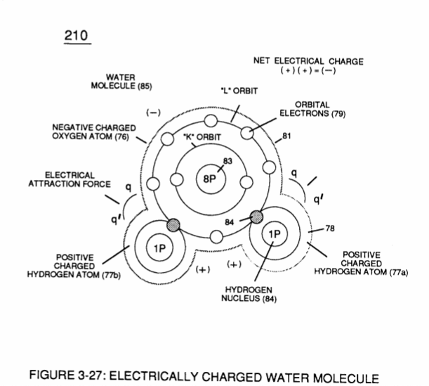](http://stanslegacy.com/uploads/images/gallery/2022-06/0BDacpaJP0lHGWi9-image-1656378712037-11-49.png) |
| [](http://stanslegacy.com/uploads/images/gallery/2022-06/YNEi4KG2I1B45y9C-image-1656378719614-11-57.png) | [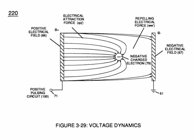](http://stanslegacy.com/uploads/images/gallery/2022-06/fITjZXRRwMwl3PEU-image-1656378725746-12-03.png) | [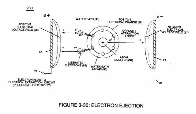](http://stanslegacy.com/uploads/images/gallery/2022-06/CQsgoEqGSUu9rFid-image-1656378734801-12-12.png) |
| [](http://stanslegacy.com/uploads/images/gallery/2022-06/OgsL3IVzrGDCFKxg-image-1656378746771-12-23.png) | [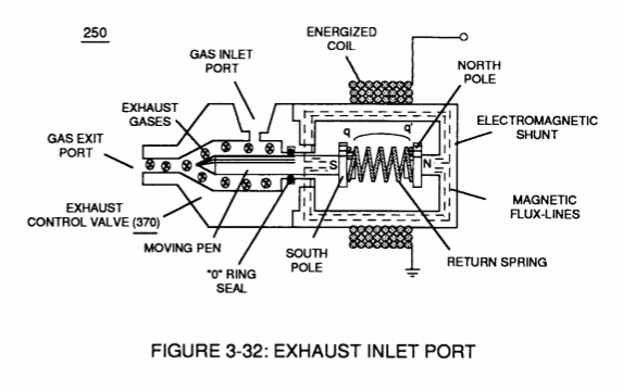](http://stanslegacy.com/uploads/images/gallery/2022-06/pOapCgBQ6IS42lnW-image-1656378762875-12-37.png) | [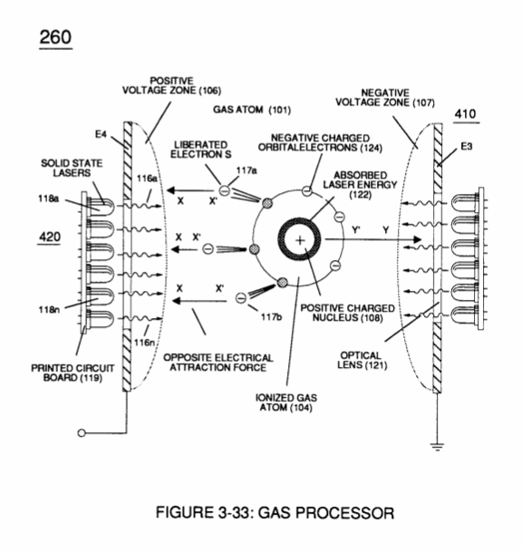](http://stanslegacy.com/uploads/images/gallery/2022-06/o91bCdwmhGK2YkOL-image-1656378770092-12-48.png) |
| [](http://stanslegacy.com/uploads/images/gallery/2022-06/9zoOMgB5P4HvxruM-image-1656378777834-12-55.png) | [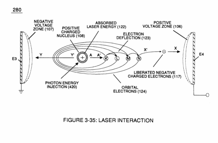](http://stanslegacy.com/uploads/images/gallery/2022-06/hTlQsR03e5wwyfA1-image-1656378783981-13-01.png) | [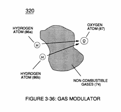](http://stanslegacy.com/uploads/images/gallery/2022-06/R2AZOnPvfeAnMAHM-image-1656378791648-13-09.png) |
| [](http://stanslegacy.com/uploads/images/gallery/2022-06/Z1cOEDkyfcxyFGzb-image-1656378799212-13-17.png) | [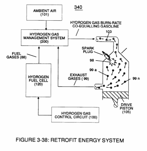](http://stanslegacy.com/uploads/images/gallery/2022-06/0EfvVS57MIAO0UhF-image-1656378806331-13-24.png) | [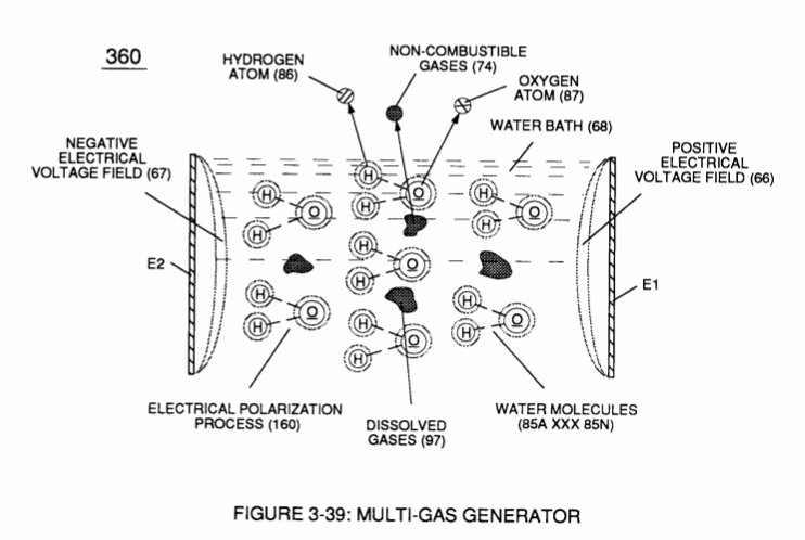](http://stanslegacy.com/uploads/images/gallery/2022-06/KldPakkTfk3bJKy7-image-1656378813558-13-31.png) |
| [](http://stanslegacy.com/uploads/images/gallery/2022-06/p6VKPQAJvBXBeNkc-image-1656378821956-13-39.png) | [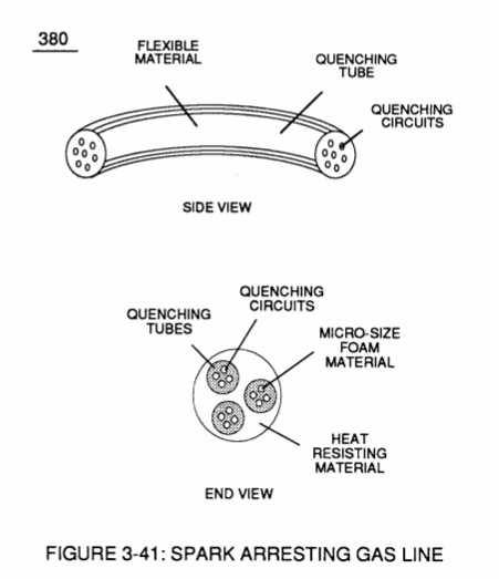](http://stanslegacy.com/uploads/images/gallery/2022-06/4OoMlgp2DEFOUfy7-image-1656378844799-14-02.png) | [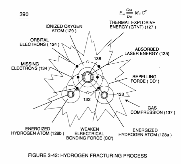](http://stanslegacy.com/uploads/images/gallery/2022-06/OiO3kpEquIGO8UgR-image-1656378852355-14-10.png) |
| [](http://stanslegacy.com/uploads/images/gallery/2022-06/yuPcuB9S3c5s4DeA-image-1656378860437-14-18.png) | [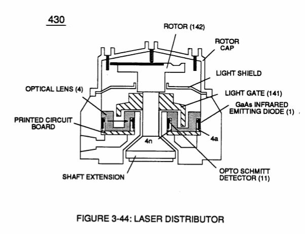](http://stanslegacy.com/uploads/images/gallery/2022-06/UW6HYJ7E6T3LtoXI-image-1656378869427-14-27.png) | [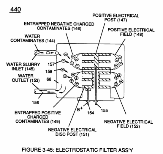](http://stanslegacy.com/uploads/images/gallery/2022-06/qJmeh9p0IgaYIYEn-image-1656378879471-14-37.png) |
| [](http://stanslegacy.com/uploads/images/gallery/2022-06/dNG7DiuOyjIkBeyo-image-1656378888370-14-46.png) | [](http://stanslegacy.com/uploads/images/gallery/2022-06/gTnbzHSxtVSAHkuI-image-1656378905139-15-02.png) | [](http://stanslegacy.com/uploads/images/gallery/2022-06/d0LXge5C3NpFuMg2-image-1656378924571-15-21.png) |