# WFC 423DA-2 - Water Fuel Injection System
# Water Fuel Injection System
[](https://stanslegacy.com/uploads/images/gallery/2024-03/8MdQQSgvSerXbNkW-image-1710802161360-49-19.png)
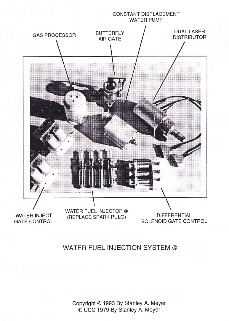
### Water Fuel Injection System
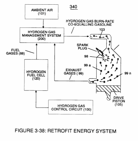
WFC Hydrogen Gas Management System is ideally suited as a retrofit energy system to both reciprocating (rotary piston engine) and turbine jet engines associated with the aviation industry...but in different ways: Reciprocating WFC fuel-kits can be similar to car design (340) of Figure (38) of [WFC (422 DA)](https://stanslegacy.com/books/the-birth-of-new-technology/chapter/wfc-422da-wfc-hydrogen-gas-management-system "WFC 422DA - WFC Hydrogen Gas Management System");
Whereas, **Water Fuel Injector Kit** (10) of Figure (1) can alternately be used as a self-contained Fuel-unit having no pressurized vessel which converts water directly into thermal explosive energy (gtnt) on demand, as illustrated (10) of Figure (1) as to Figure (40) of Figure (2B 1-2).
| [](https://stanslegacy.com/uploads/images/gallery/2024-03/8zEBCXuDDmHtlhzx-image-1710804322371.png) | [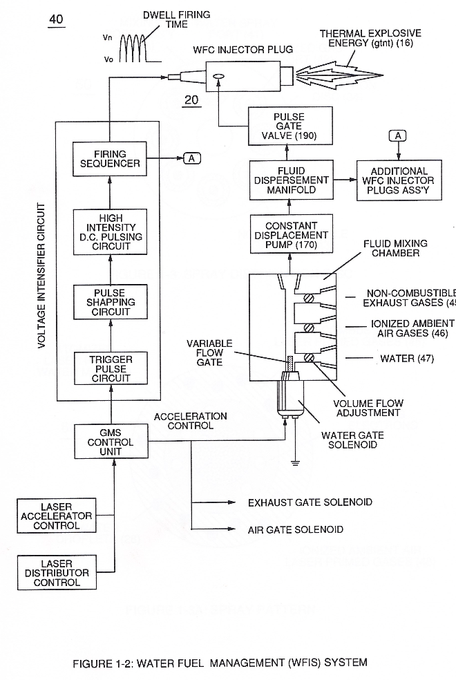](https://stanslegacy.com/uploads/images/gallery/2024-03/2wTszFLYLqsvlX2S-image-1710818673862-24-31.png) |
Operationally, Water Fuel injector assembly (10) of Figure (1) as to (40) of Figure (2B) performs several functions simultaneously to produce thermal explosive energy-yield (gtnt) (16) on demand:
First water mist (47) of Figure (1-3A) is injected into fuel-mixing chamber (35) of Figure (3B) by way of water spray ports (41a xxx 41n) of Figure (3A);
Secondly, **ionized air gases** (46a xxx 46n) of Figure (3A) *(laser primed ambient air gases having missing electrons)* produced by **Ambient Air Ionizer** (80) of Figure (4) as to Figure (1) and **non-combustible gases** (45) of Figure (3A) are intermixed with expelling water mist (47a xxx 47n) to form **Water-fuel mixture** (48) by way of **gas mixing disc** (34) of Figure (3B) as to (30) of Figure (2A);
thirdly, the resultant moving **Water-Fuel mixture** (48) of Figure (3B) enters into **Voltage Igniter Stage** (180) of Figure (3B) and exposed to high intensity voltage fields (33 / 36) (typically 2,000 volts or above @ 10 Khz or above) opposite electrical polarity (E7 / E8)
...which, in turn, not only performs electrical polarization process (160) of Figure (25) undergoing **Dielectric Resonant** (240) of Figure (30); but, also sets up and triggers **Hydrogen Fracturing Process** (390) of Figure (41) as to Figure (6) under control state (on demand) via electrical-static spark ignition (49 / 51) of Figure (3B)....releasing thermal explosive energy (gtnt) (16) passing beyond gas exit port (32) of Figure (3B), as further illustrated in Figure (2) as to Figure (1).
To ensure proper energy-flame projection and subsequent energy-flame stability, constant placement water pump (170) causes and allows **ionized ambient air gases** (46), **non-combustible gases** (45), and **water** (47) to be displaced under static pressure up to and beyond 125 psi respectively.
**Energy-Flame** density is enhanced and sustained by causing ionized gases (46a xxx 46n) of s**pray port** (42) to be deflected into **liquid spray path** (41), together **water mist** (47) and **ionized air** (46) are, now, directed toward and deflected through non-combustible gas spray path producing uniformed **water-fuel mixture** (48), as illustrated in Figure (3B).
**Energy-Flame** temperature is regulated by controlling the volume flow-rate of each fluid mediums (47 / 45/ 46) in direct relationship to applied voltage intensity (33 /36), as further stated in Figure (2B) as to Figure (3B).
To elevate **Energy-flame-temperature** still further, help increase **fluid-displacement** (46/47) while maintaining or reducing the volume flow rate of non-combustible gases (45) during an increase of applied voltage amplitude (Vo x Vn) of Figure
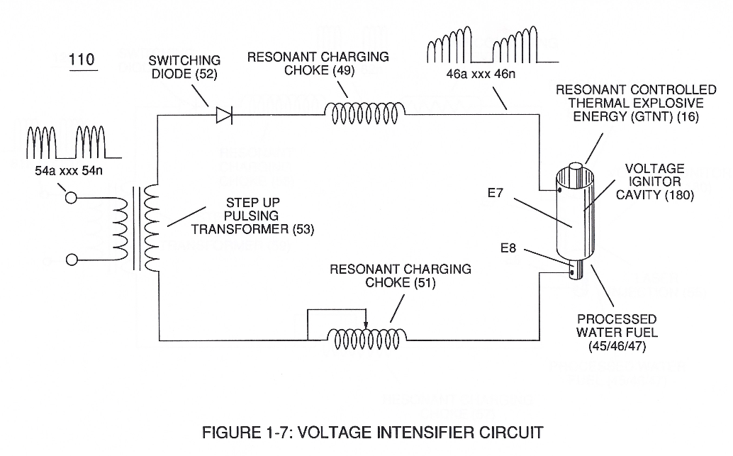
(32) as to **Voltage Intensifier Circuit** (110) of Figure (7) and **Electron Extraction Circuit** (120) of Figure (8).
To lower Energy-flame temperature simply increase the amount of non-combustible gas (45a xxx) or reduced the fluid flow rate (45 / 46/ 47)) uniformly while lowering pulse voltage amplitude (xxx Vo).
To establish a predetermined or given Energy-flame temperature adjust fluid-medium (45 / 46 / 47)) and applied voltage amplitude (Vo xxx) independent of each other to obtain the desired results.
The resultant energy-flame pattern is further maintained by allowing the ignited,compressed, and moving gases (29) of Figure (3B) to be projected to, pass through and beyond **nozzle-port** (32) under pressure due to gas expansion caused by thermal gas ignition.
**Voltage Igniter Stage** (180) of Figure (3B) as to **Voltage Intensifier Circuit** (110) Figure (7) as to **Extraction Circuit** (120) of Figure (8) performs several functions simultaneously to initiate and trigger thermal explosive energy-yield (gtnt) (16) beyond normal gas burning levels:
Water droplets (28a xxx 28n) escaping from spray-mist (47) and exposed to high intensity voltage fields of opposite polarity 33/ 36) are stimulated to undergo Electrical Polarization Process (160) of Figure (25)...which not only separates and splits the unlike atoms of the water molecule but also causes the unlike atoms (hydrogen atoms 77a / 77b and oxygen atom 76) to experience electron ejection (230) of Figure (29) as to (71) of Figure (8) since voltage intensifier circuit (110) of Figure (7) inhibits and prevents electron flow to enter into gas ignition process (180), as further illustrated in Figure (6).
The newly liberated water molecule atoms (oxygen 76 and hydrogen atoms 77a / 77b) immediately interact with laser primed ionized ambient air gases (7a xxx In of Figure 1-8) (see [WFC memo 420](https://stanslegacy.com/books/the-birth-of-new-technology/chapter/wfc-420-hydrogen-fracturing-process "WFC 420 - Hydrogen Fracturing Process")) to cause the resultant highly energized and mass destabilized combustible gas atoms (93a xxx 93n) of Figure (8) to perform **Hydrogen Fracturing Process** (80) of Figure (7)
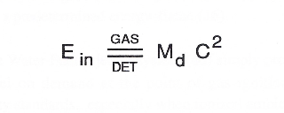
when electrostatic force (14/16) thermally ignites (*kinetic agitation*) destabilized water-fuel mixture (93a xxx 93n) under gas compression... preventing the formation of the water molecule during thermal gas ignition....satisfying **Energy Gas Detonation Equation**.
[](https://stanslegacy.com/uploads/images/gallery/2024-03/nDzBsuqGP8VkgXQY-image-1710817020257-56-58.png)
which states:
That, whenever the mass-size of a combustible gas atom is decreased (Md), thermal explosive energy-yield (gtnt) is increased (Ein) during thermal gas combustion (Gas // Detonation.), as so illustrated in (100) Figure (6) as to (90) of Figure (5).
[](https://stanslegacy.com/uploads/images/gallery/2024-03/JqeitiAp4qURSnQb-image-1711239500177-18-17.png)
Incoming ambient air gases (5a xxx 5n) become laser primed and ionized when passing through Ambient Air Ionizer (Gas Processor) (80) of Figure (4) as to (10) of Figure (1) since **electron extraction circuit** (120) of Figure (8) not only captures and consumes ejected electrons (7a cx 7n) of Figure (6); but, also prevents electron flow into destabilizing gas process (180), as so illustrated in Figure (3B).
In terms of performance reliability and safety, ionized air gases (46a xxx 46n) and liquid water (47a xxx 47n) do not become energy activated (volatile) until water-fuel mixture (48) reaches **Voltage Igniter Stage** (180).
Injected non-combustible gases (45a xxx 45) retards and controls the combustion rate of the **Hydrogen Fracturing Process** (100) of Figure (6) during gas-ignition.
In other or alternate applications, laser primed ionized liquid oxygen (68) of Figure (1-10) CF\* memo 420) and laser primed liquid hydrogen (69) of Figure (1-10) stored in separate fuel tanks can be used in place of fuel-mixture (48); or, liquefied ambient air gases (6) alone with source (8) can, also, be substituted as a fuel-source (48) to trigger Hydrogen Fracturing 10).
Additional WFC Injector Assemblies (20) of Figure (2) are arranged in cluster array (20a xxx 20n) to increase energy-yield output (16a xxx 16n) of Figure (10 / 1 / 12).
WFC injector assembly (10) of Figure (1) as to (30) of Figure (2A) is design variable to be retrofitable by replacing fossil-fuel injector ports affixed to jet engines (see Figure 11), heating systems (Figure 10), rockets engines (Figure 12), or even car spark plugs (130) of Figure (9) which simply uses **Water Fuel management** (WFMS) system **fluid-metering system** (40) to control
gas ignition (16), as illustrated in (40) of Figure (2B).
Sequential pulsing of **Water Fuel Injector** (20/30) of Figure (1) as to (40) of Figure (2B) is system activated by **Pulse Gate Valve** (190) of Figure (1) to further control a predetermined **energy-flame** (16).
In essence, then, the **Water Fuel Injector** system (40) simply processes and converts water into a useful hydrogen fuel on demand at the point of gas ignition...thereby, co-equally or superseding fossil-fuel safety standards...
especially when ionized **ambient air gases** (46a xxx 46n) and **non-combustible gases** (45a xxx 45n) are intermixed with **water supply** (47) prior to entering.
Water Fuel Injector Plug (20 / 30), as illustrated in (40) of Figure (2B) as to (10) of Figure (1).
# Voltage Intensifier Coil Assembly
[](https://stanslegacy.com/uploads/images/gallery/2024-03/pRn0axjkdpiaDyC0-image-1710802229262-50-27.png)
#### 3-1 Coil Wrap Assembly
[](https://stanslegacy.com/uploads/images/gallery/2024-03/CNhbEr80F654Jl6q-image-1711247092269-24-49.png)
#### 3-2 (VIC) Coil Assembly
[](https://stanslegacy.com/uploads/images/gallery/2024-03/0ALjEvukLRwxn6uG-image-1711247119564-25-17.png)
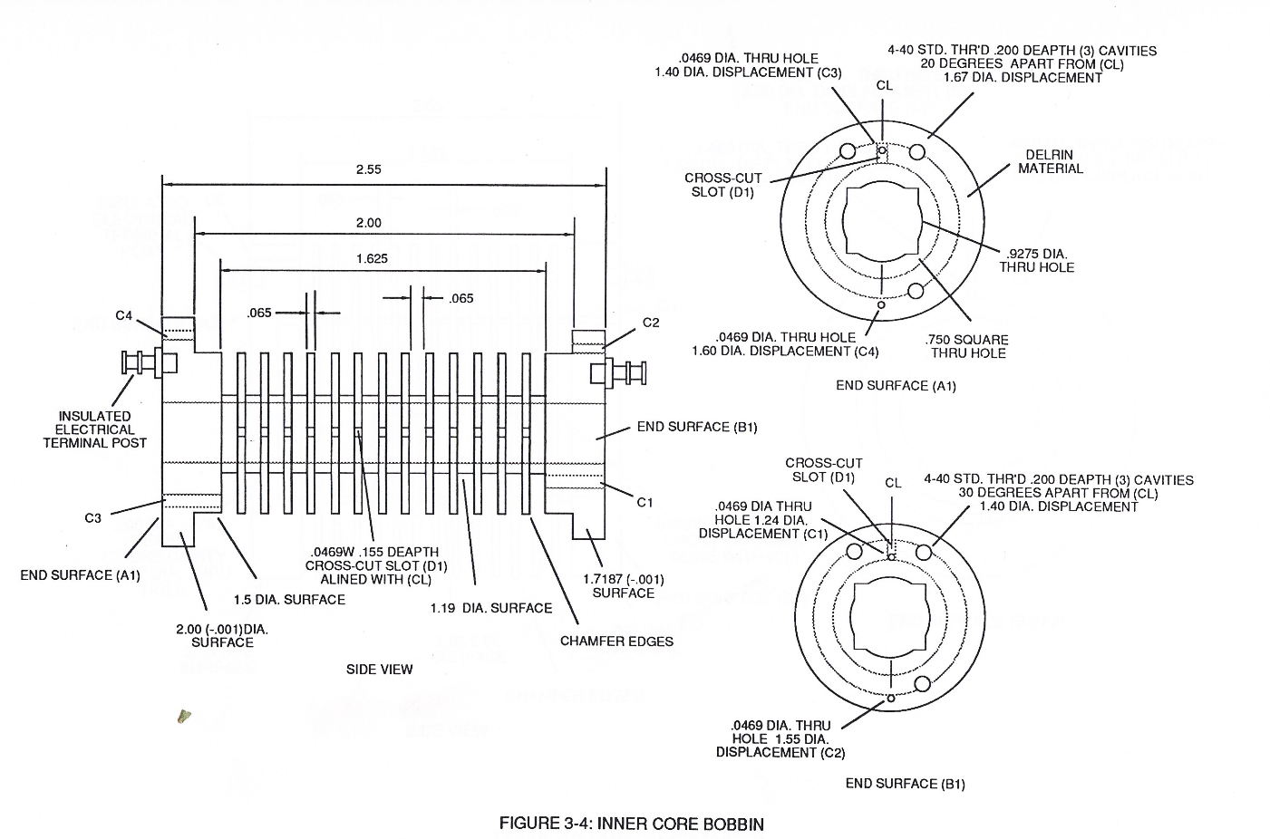
#### 3-4 Inner Core Bobbin
[](https://stanslegacy.com/uploads/images/gallery/2024-03/48gSOp2ETgsNuQ6v-image-1711247156920-25-54.png)
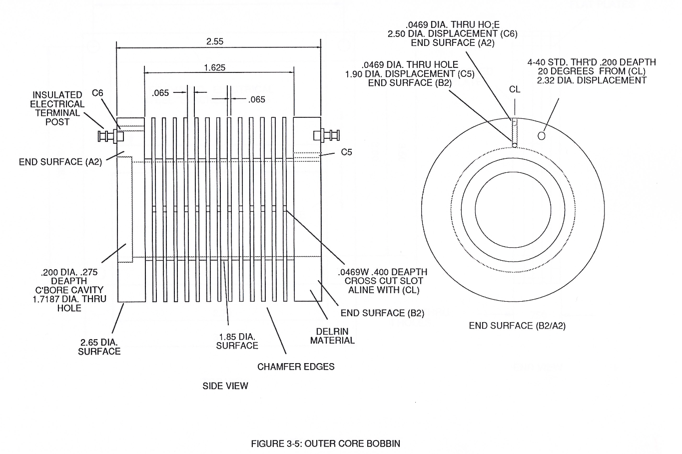
#### 3-5 Outer Core Bobbin
[](https://stanslegacy.com/uploads/images/gallery/2024-03/uKklpAEgDo1wjKOJ-image-1711247178828-26-17.png)
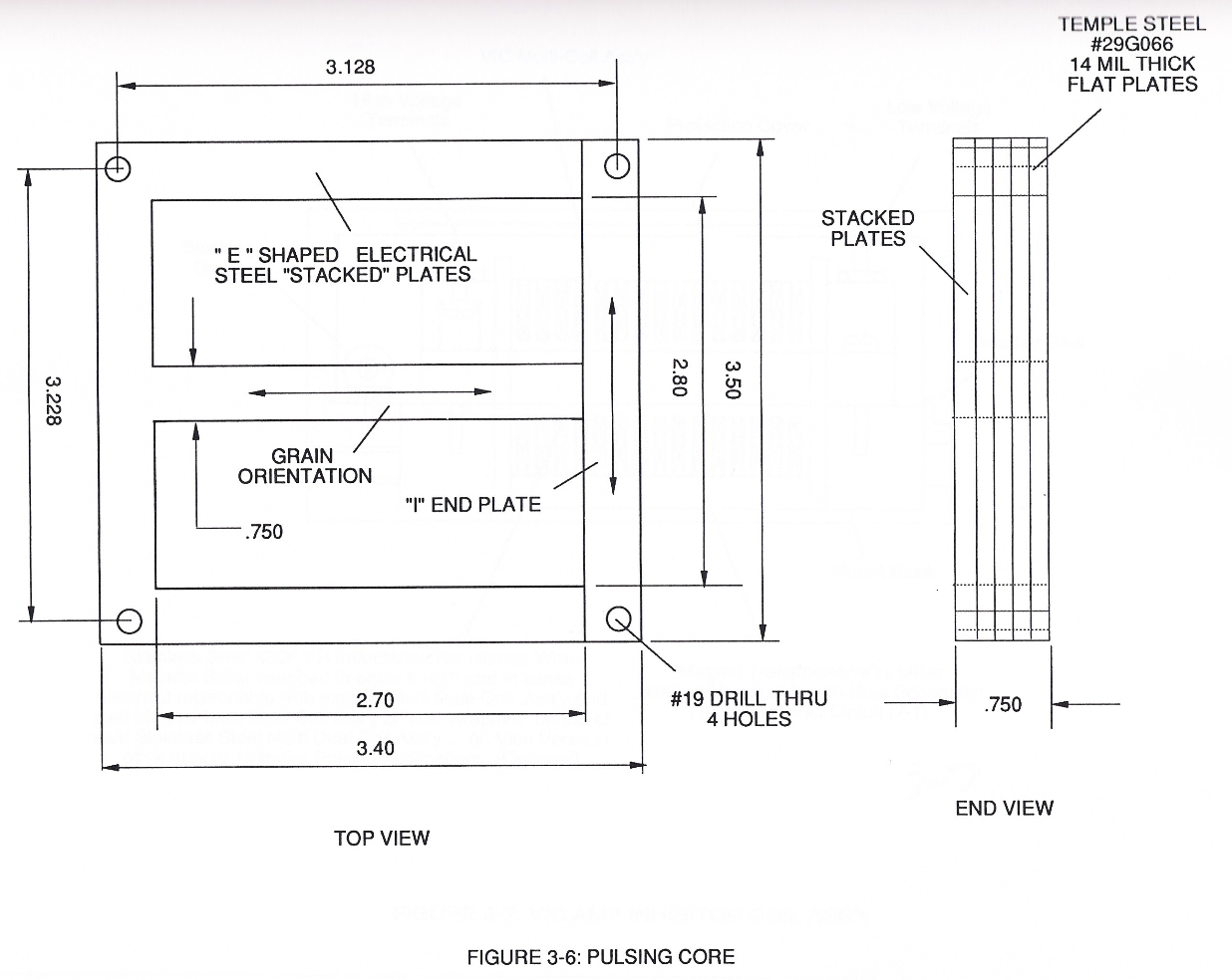
#### 3-6 Pulsing Core
[](https://stanslegacy.com/uploads/images/gallery/2024-03/EjdzJ8osFvioWjw3-image-1711247216898-26-54.png)
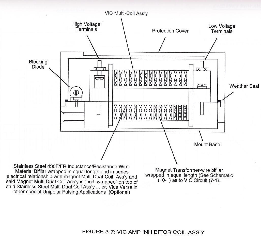
#### 3-7 VIC Amp Inhibitor Coil Ass'y
[](https://stanslegacy.com/uploads/images/gallery/2024-03/O2CN6KjQanuhct3q-image-1711247238552-27-14.png)
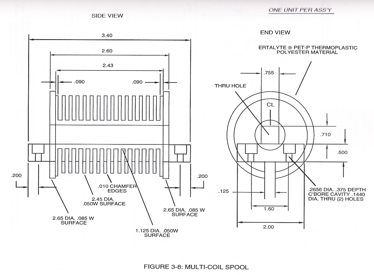
#### 3-8 Multi-Coil Spool
[](https://stanslegacy.com/uploads/images/gallery/2024-03/aN1CRYSXnhqEsbeA-image-1711247267796-27-45.png)
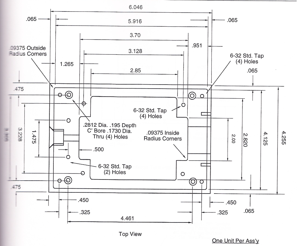
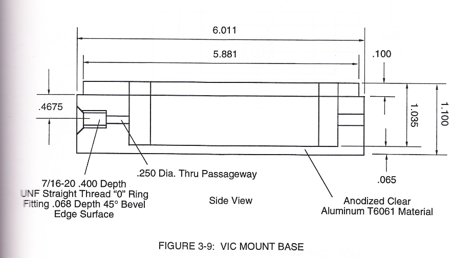
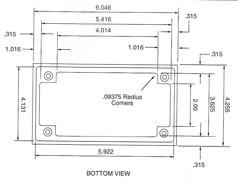
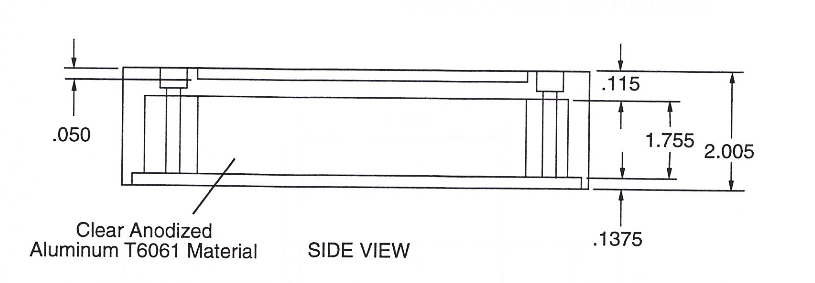
#### 3-9 VIC Mount Base
| [](https://stanslegacy.com/uploads/images/gallery/2024-03/aOVQx4Xuf4klXGGq-image-1711247310383.png)
| [](https://stanslegacy.com/uploads/images/gallery/2024-03/OapCunRG0hP7fU1h-image-1711247338589-28-56.png)
|
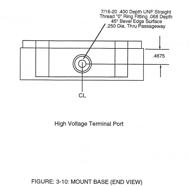
#### 3-10 Mount Base (End View)
| [](https://stanslegacy.com/uploads/images/gallery/2024-03/crUsj6MNevMDyOoR-image-1711247377552-29-35.png)
| [](https://stanslegacy.com/uploads/images/gallery/2024-03/4bNCGaVRxZ3rVg77-image-1711247386279-29-44.png)
|
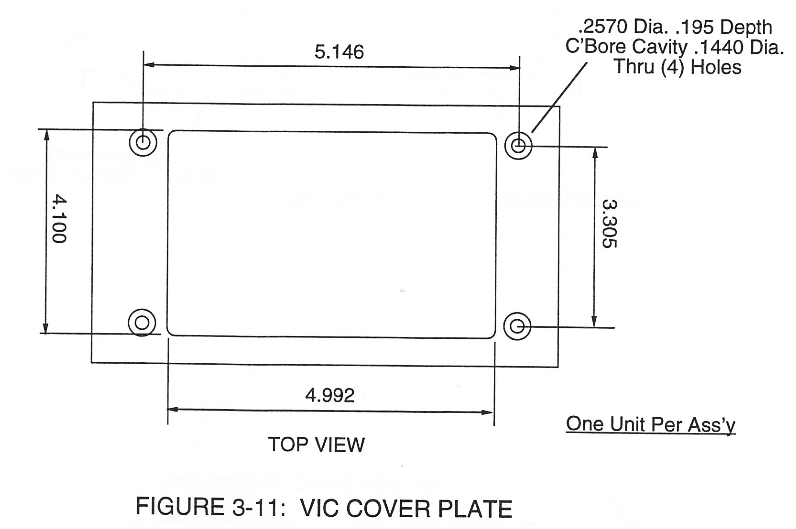
#### 3-11 VIC Cover Plate
| [](https://stanslegacy.com/uploads/images/gallery/2024-03/PcFU3C5oBSKtSNY3-image-1711247422276-30-20.png)
| [](https://stanslegacy.com/uploads/images/gallery/2024-03/WR0rey0Qx6wN1pdc-image-1711247432446-30-30.png)
| [](https://stanslegacy.com/uploads/images/gallery/2024-03/3b32XfhWJy63Fm9T-image-1711247443215-30-41.png)
|
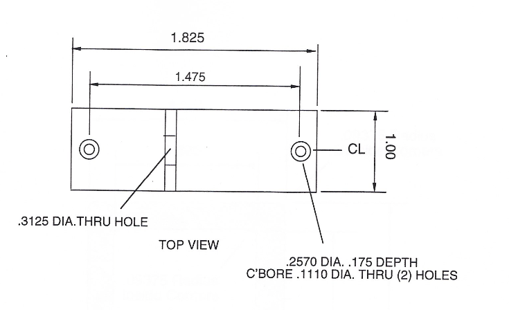
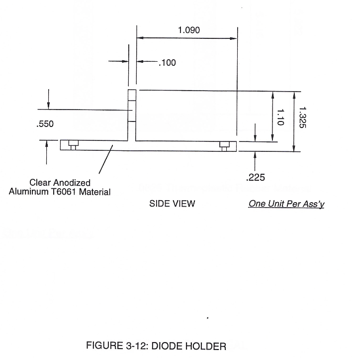
#### 3-12 Diode Holder
| [](https://stanslegacy.com/uploads/images/gallery/2024-03/3j4LZWnfpeDAZie1-image-1711247469699-31-04.png)
| [](https://stanslegacy.com/uploads/images/gallery/2024-03/HjtglwE9VahP3tmH-image-1711247477570-31-15.png)
|
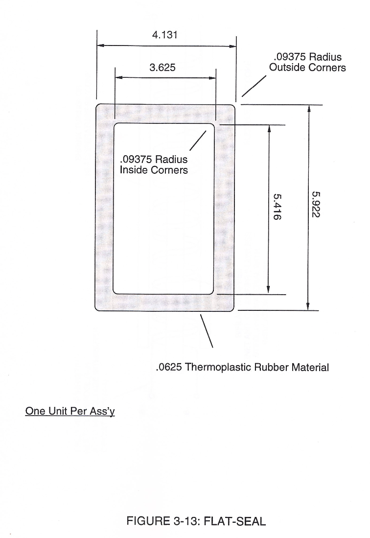
#### 3-13 Flat Seal
[](https://stanslegacy.com/uploads/images/gallery/2024-03/kDtCt1XxqThsnfZc-image-1711247505264-31-43.png)
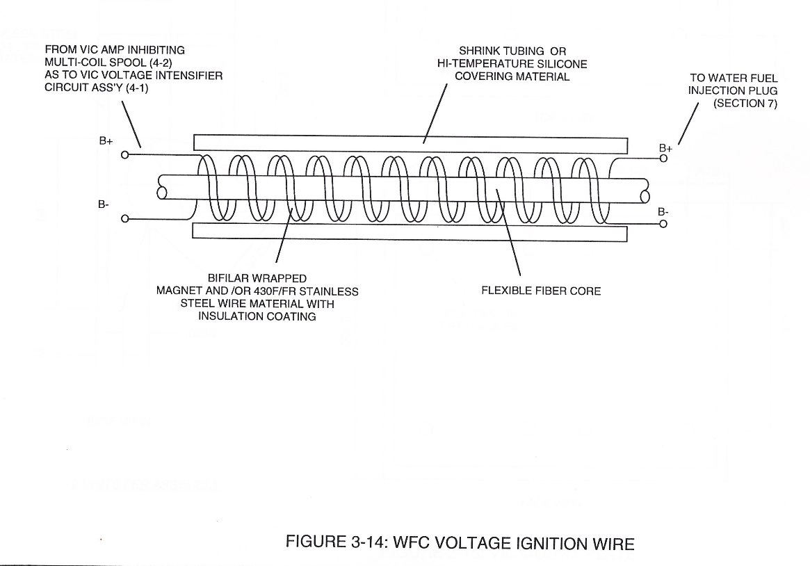
#### 3-14 WFC Voltage Ignition Wire
[](https://stanslegacy.com/uploads/images/gallery/2024-03/iE5QtzZMBm7EhAsG-image-1711247537637-32-14.png)
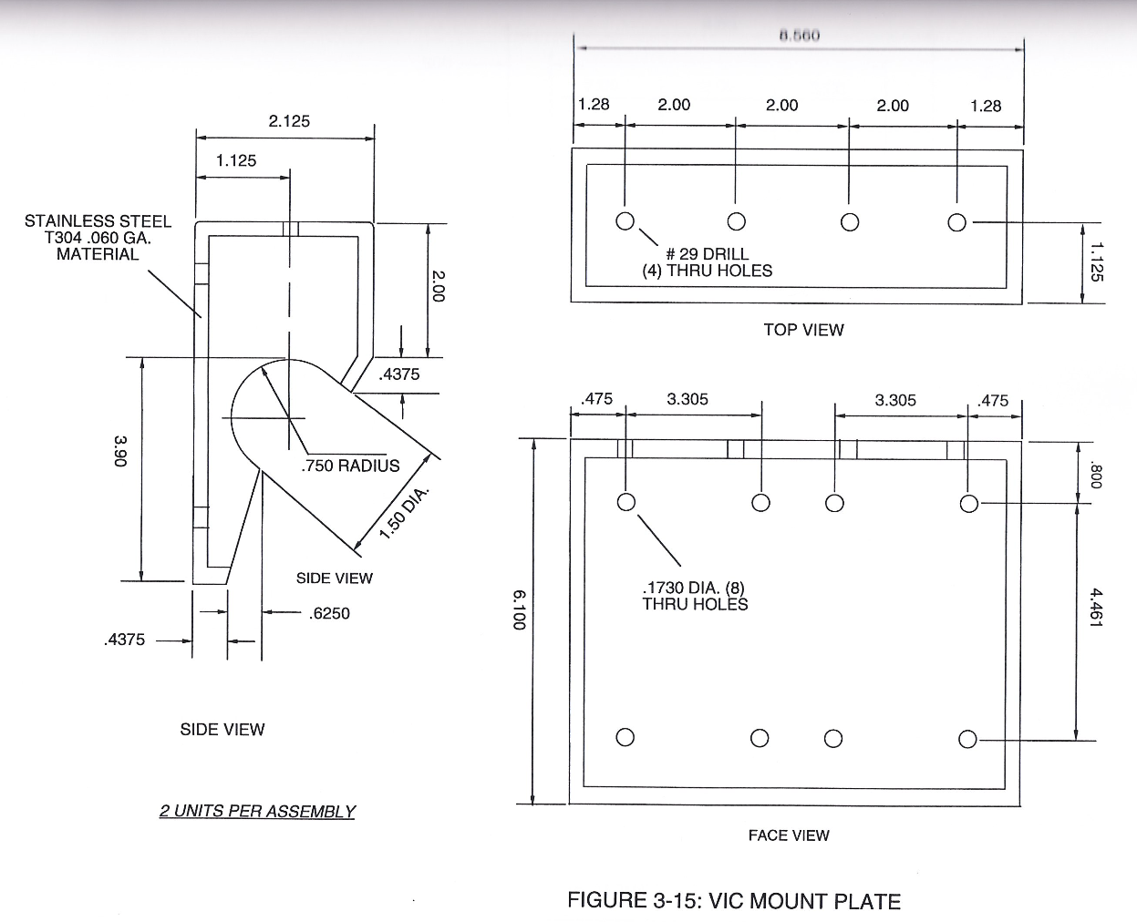
#### 3-15 VIC Mount Plate
[](https://stanslegacy.com/uploads/images/gallery/2024-03/3DBnGd3FVMsDAiFa-image-1711247565330-32-43.png)
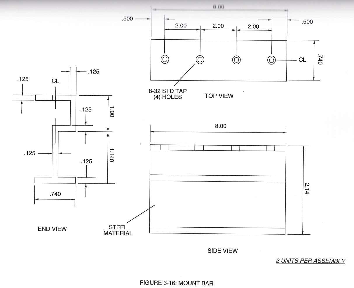
#### 3-16 Mount Bar
[](https://stanslegacy.com/uploads/images/gallery/2024-03/ko3HX1OMJuIP5WbU-image-1711247587576-33-04.png)
# Electronic Circuit Design
[](https://stanslegacy.com/uploads/images/gallery/2024-03/lZlnz62nIjCpw13b-image-1710802275069-51-12.png)
[](https://stanslegacy.com/uploads/images/gallery/2024-03/DDZDNaEaFI41VZHE-image-1710802635956-57-11.png)
[](https://stanslegacy.com/uploads/images/gallery/2024-03/QlZT5ZEekdSYbDIy-image-1710802649524-57-27.png)
[](https://stanslegacy.com/uploads/images/gallery/2024-03/TdCYnqIbBbPp33iR-image-1710802664338-57-41.png)
[](https://stanslegacy.com/uploads/images/gallery/2024-03/AGW5zAsuYqXhprZs-image-1710802678886-57-56.png)
[](https://stanslegacy.com/uploads/images/gallery/2024-03/fGv1lhsb1gwt5XPY-image-1710802694044-58-11.png)
[](https://stanslegacy.com/uploads/images/gallery/2024-03/cKWI8lE0RETBUsBW-image-1710802713158-58-31.png)
[](https://stanslegacy.com/uploads/images/gallery/2024-03/MydU1h79mvfpIOle-image-1710802730063-58-47.png)
[](https://stanslegacy.com/uploads/images/gallery/2024-03/eLp1LvS5QfiSOrRS-image-1710802746503-59-04.png)
[](https://stanslegacy.com/uploads/images/gallery/2024-03/JeDFMGj3Ympyqg4J-image-1710802759846-59-18.png)
[](https://stanslegacy.com/uploads/images/gallery/2024-03/qL0CQfn6WDTKVe7q-image-1710802776609-59-34.png)
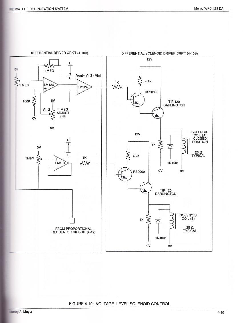
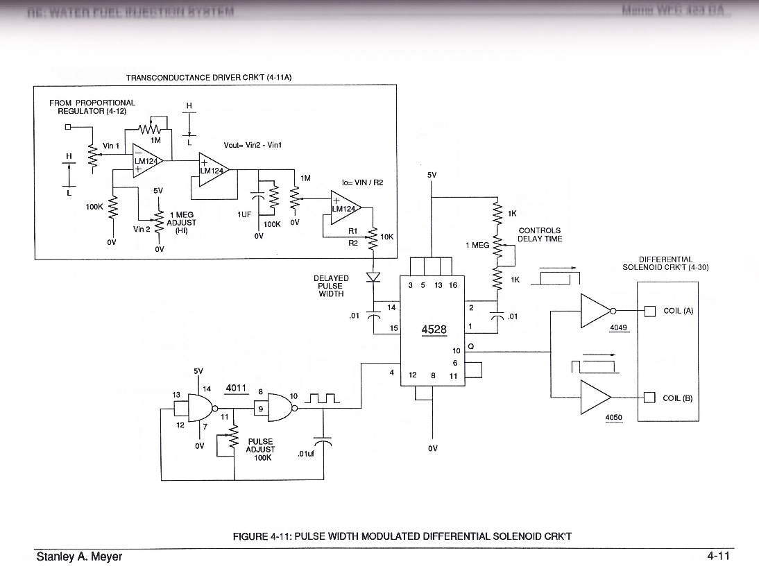
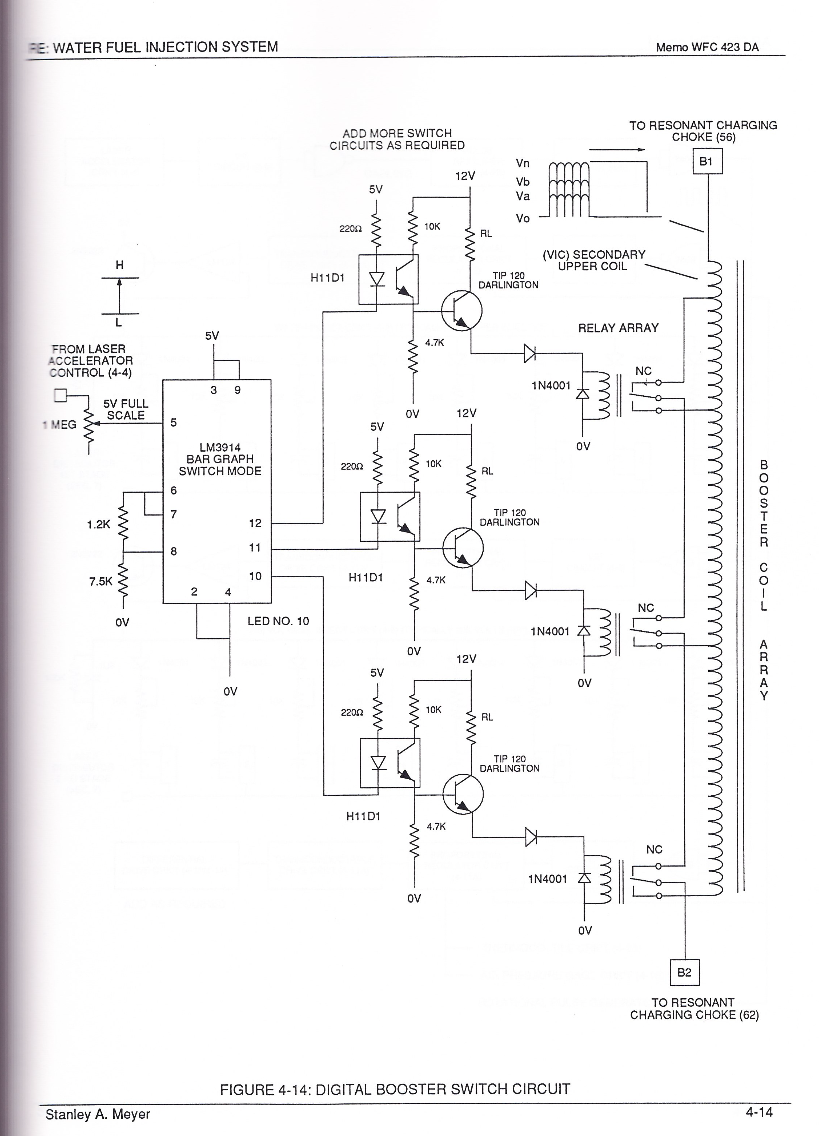
#### Pulse Width Modulated Differential Solenoid Circuit
[](https://stanslegacy.com/uploads/images/gallery/2024-03/fYbApOWPPaU7XMA5-image-1710802797625-59-55.png)
[](https://stanslegacy.com/uploads/images/gallery/2024-03/rdD2KJWnKhnHIdd3-image-1710802812163-00-08.png)
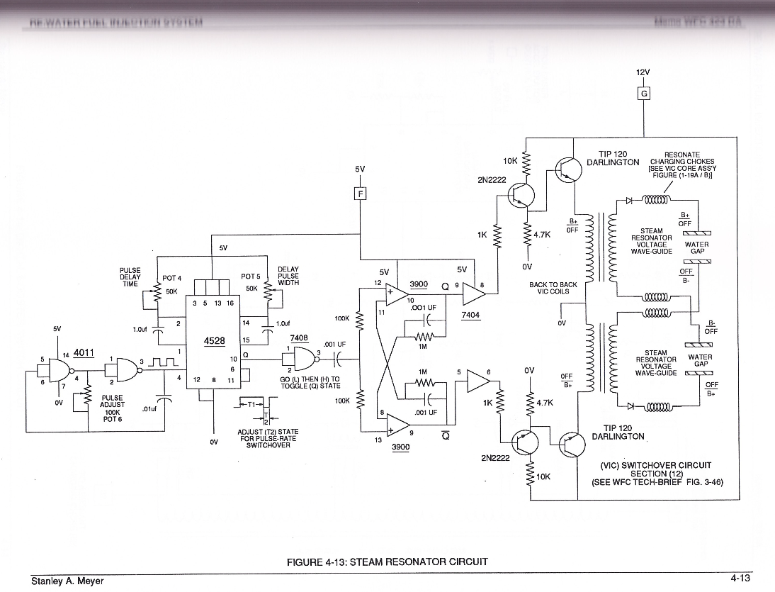
#### Steam Resonator Driver Circuit
[](https://stanslegacy.com/uploads/images/gallery/2024-03/hKfm1gokuliN2Q3M-image-1710802826914-00-24.png)
[](https://stanslegacy.com/uploads/images/gallery/2024-03/D2mxL5gAMCIGw29t-image-1710802852414-00-50.png)
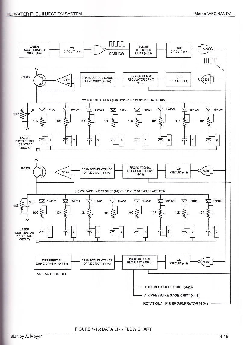
#### Data Link Flow Chart
[](https://stanslegacy.com/uploads/images/gallery/2024-03/xfAr98glDuu0kVdE-image-1710802864859-01-02.png)
####
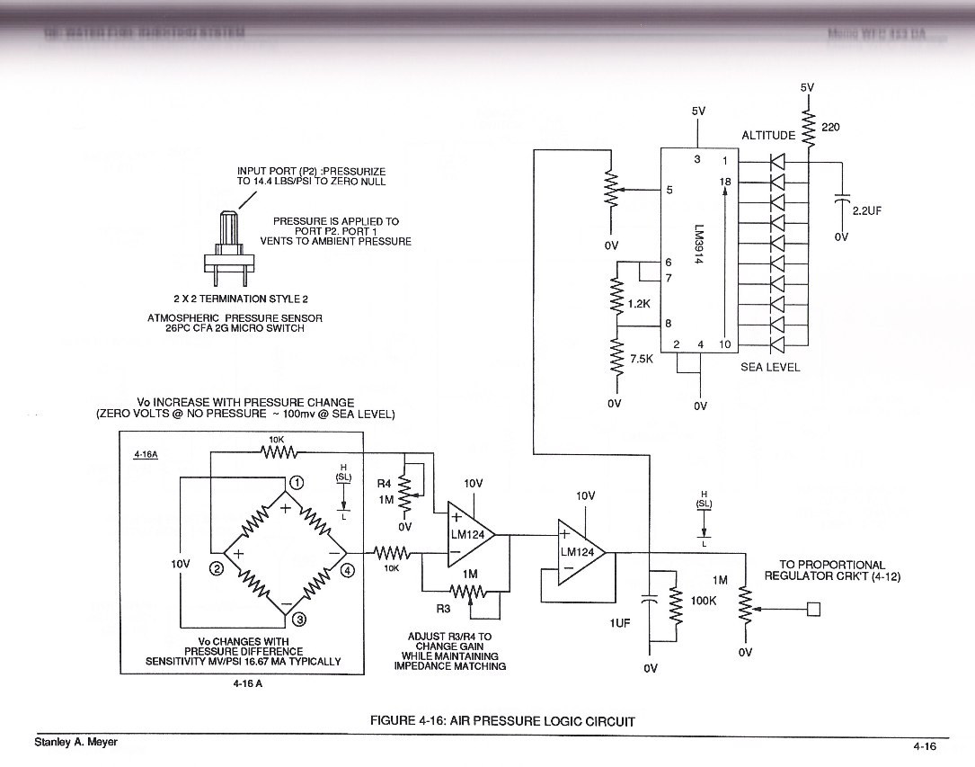
#### Air Pressure Logic Circuit
[](https://stanslegacy.com/uploads/images/gallery/2024-03/jbewNUltNLYz7b5r-image-1710802889150-01-27.png)
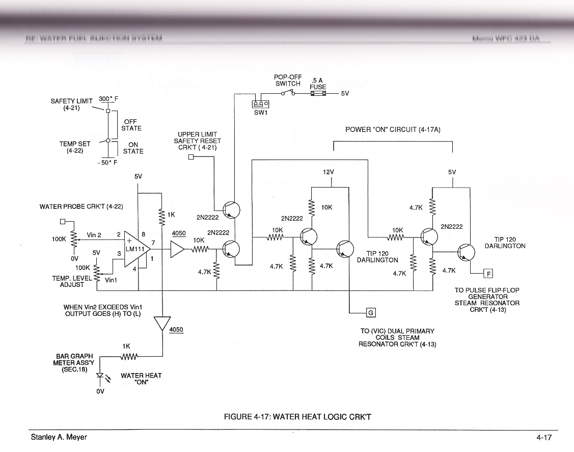
#### Water Heat Logic Circuit
[](https://stanslegacy.com/uploads/images/gallery/2024-03/PVmjcCIiEthdmK7w-image-1710802915649-01-53.png)
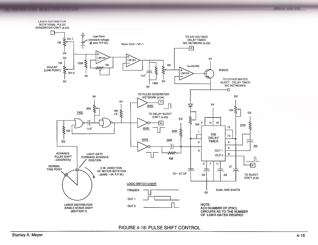
#### Pulse Shift Control
[](https://stanslegacy.com/uploads/images/gallery/2024-03/zERGhPdst4UNgUZ4-image-1710802948032-02-25.png)
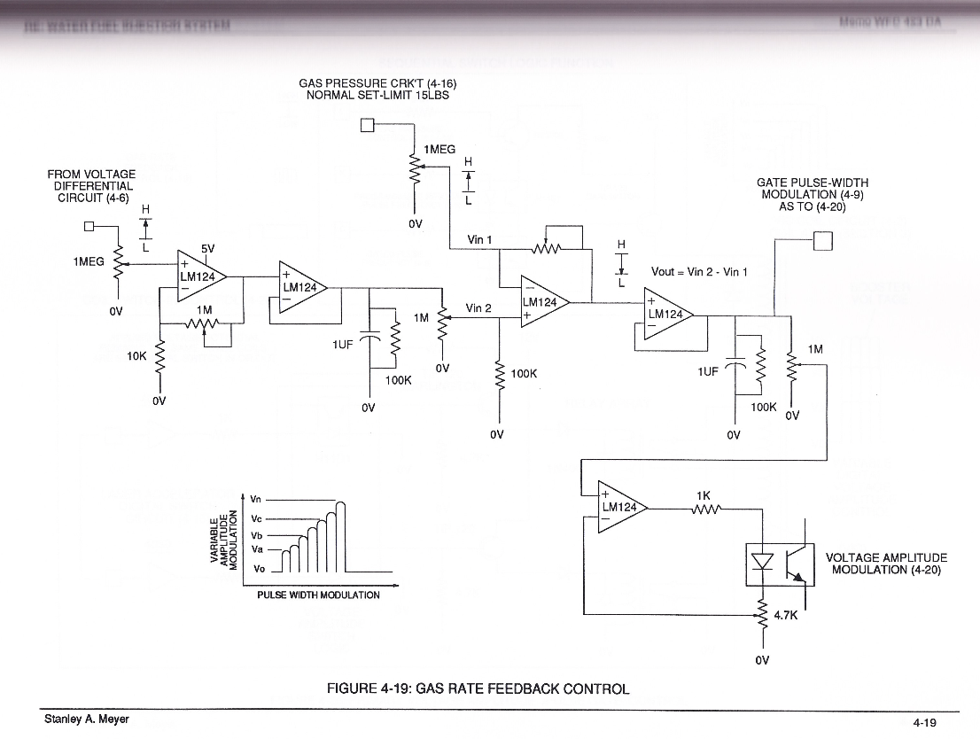
#### Gas Rate Feedback Control
[](https://stanslegacy.com/uploads/images/gallery/2024-03/nubs3ErVs1ceY5Pc-image-1710802967939-02-45.png)
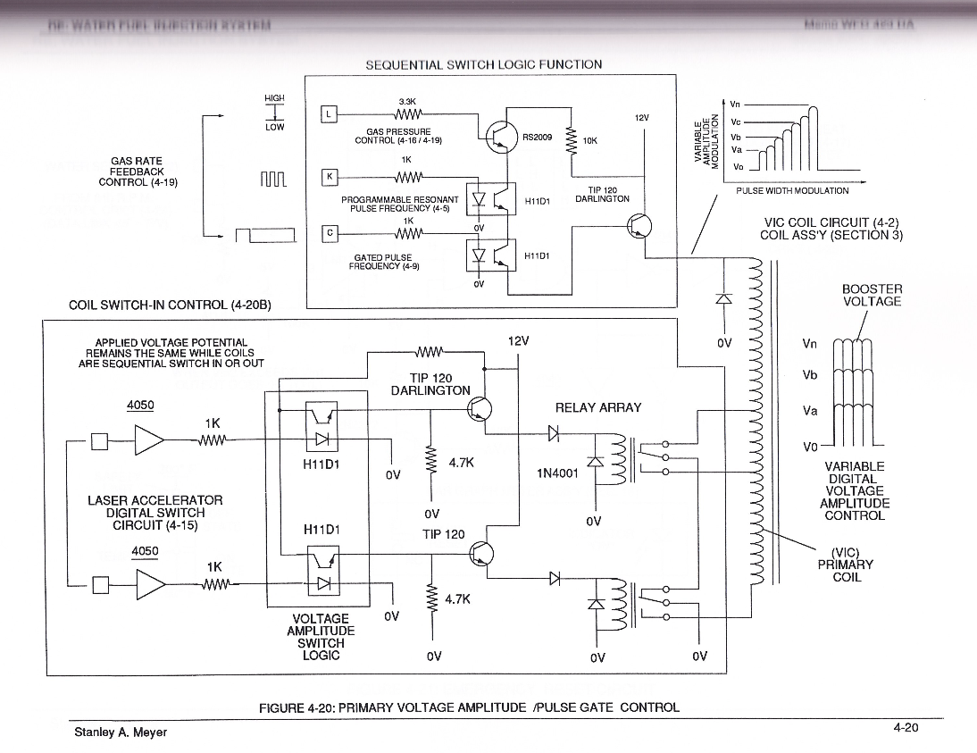
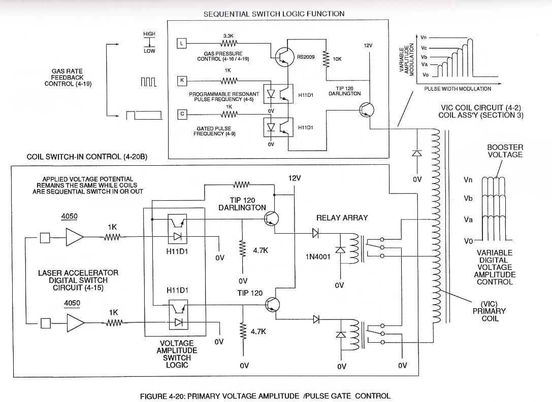
#### Primary Voltage Amplitude / Pulse Gate Control
[](https://stanslegacy.com/uploads/images/gallery/2024-03/buEKFUeZFOSqlt0C-image-1710802987115-03-04.png)
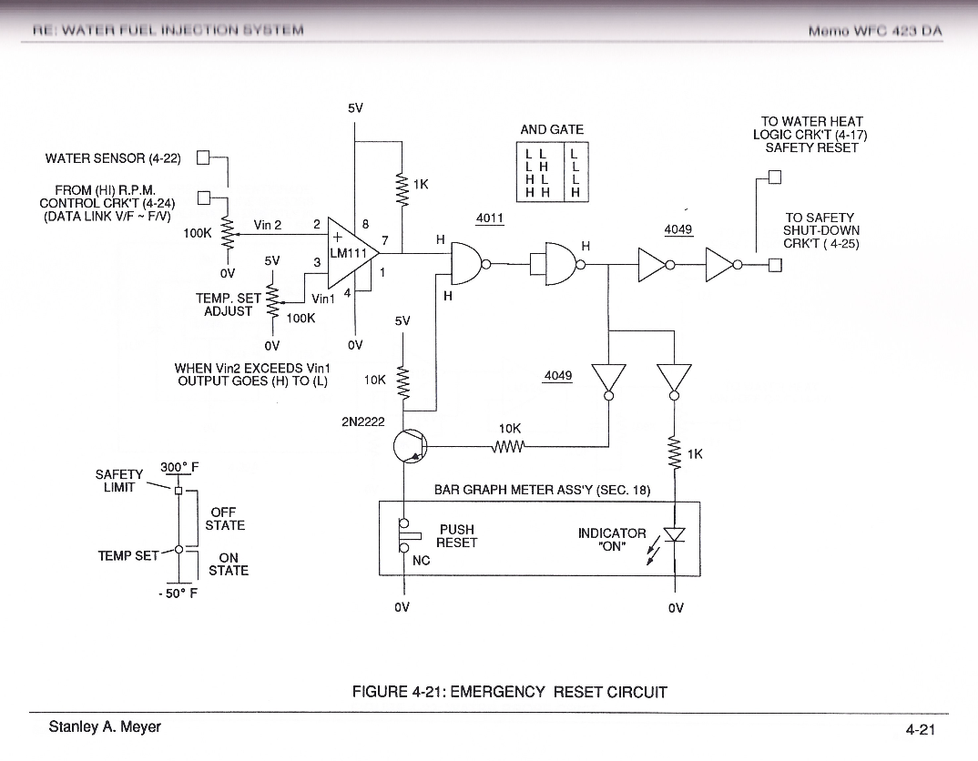
#### Emergency Reset Circuit
[](https://stanslegacy.com/uploads/images/gallery/2024-03/PZ4eX368WQQKmu61-image-1710803017074-03-33.png)
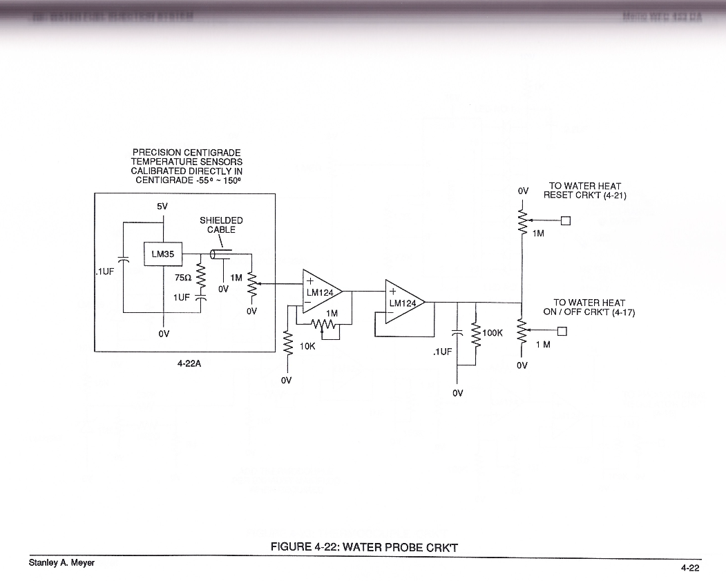
#### Water Probe Circuit
[](https://stanslegacy.com/uploads/images/gallery/2024-03/6wgDATyLdQKxlU7q-image-1710803046357-04-04.png)
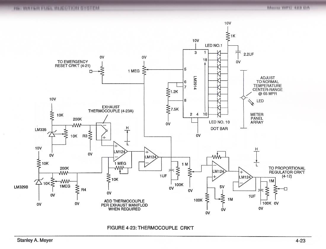
#### Thermocouple Circuit
[](https://stanslegacy.com/uploads/images/gallery/2024-03/yoQT6f6cbCc4lNdB-image-1710803068578-04-26.png)
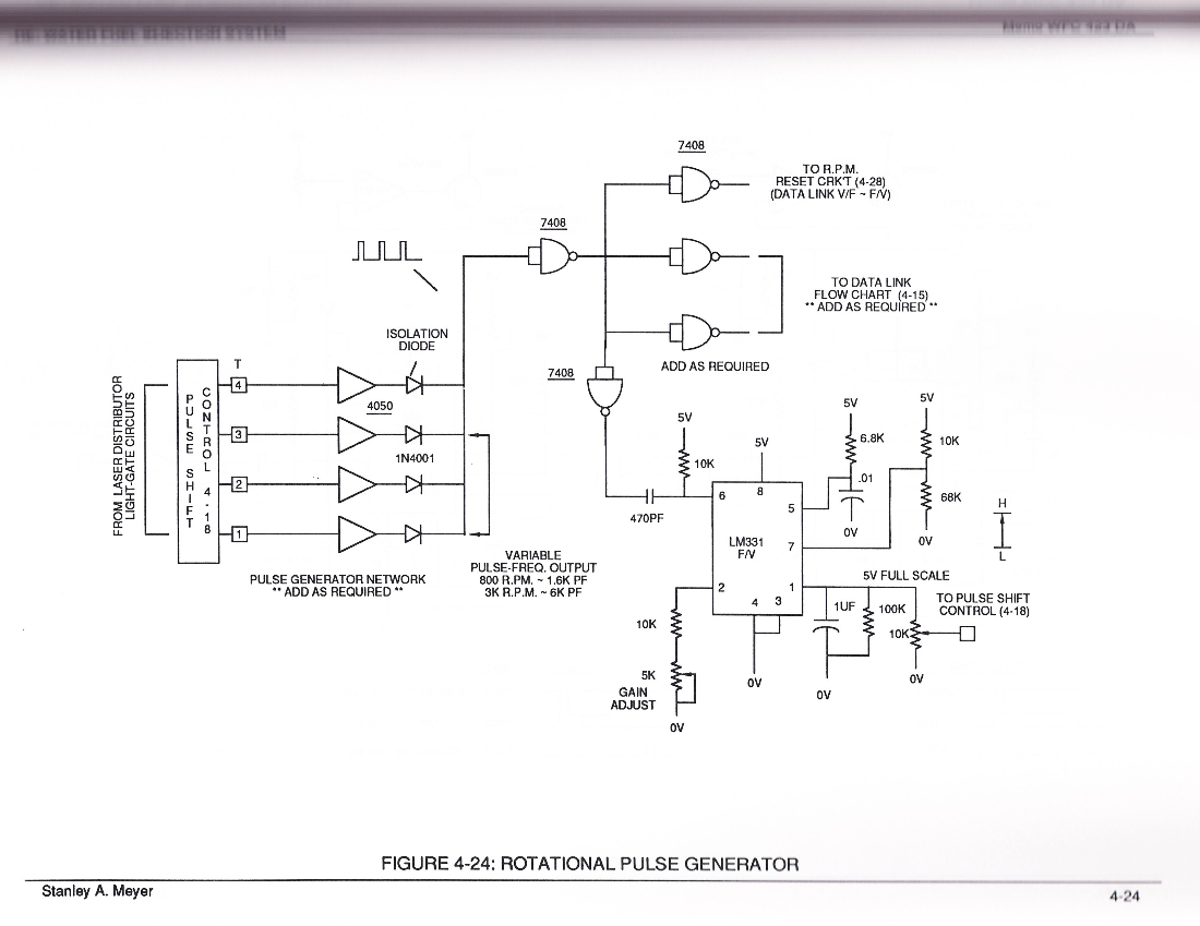
#### Rotational Pulse Generator
[](https://stanslegacy.com/uploads/images/gallery/2024-03/OIOqbX5rKQoHZ7qp-image-1710803090199-04-48.png)
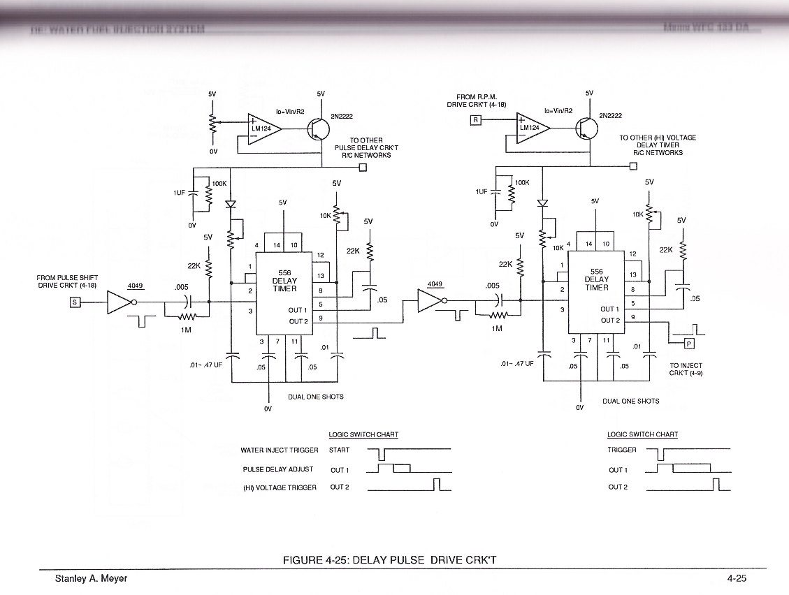
#### Delay Pulse Drive Circuit
[](https://stanslegacy.com/uploads/images/gallery/2024-03/yslghVz6FWnv3wVJ-image-1710803111848-05-09.png)
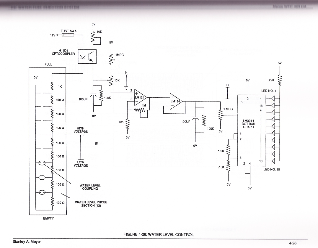
#### Water Level Control
[](https://stanslegacy.com/uploads/images/gallery/2024-03/Rz2w9n2R2JaKVjhm-image-1710803137238-05-35.png)
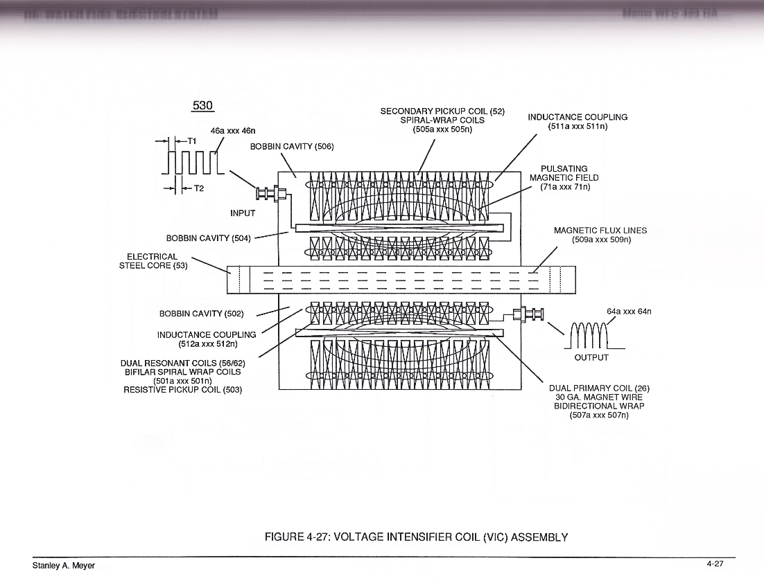
#### Voltage Intensifier Coil (VIC) Assembly
[](https://stanslegacy.com/uploads/images/gallery/2024-03/8bKGys5GEQrfJ9Iz-image-1710803318108-08-36.png)
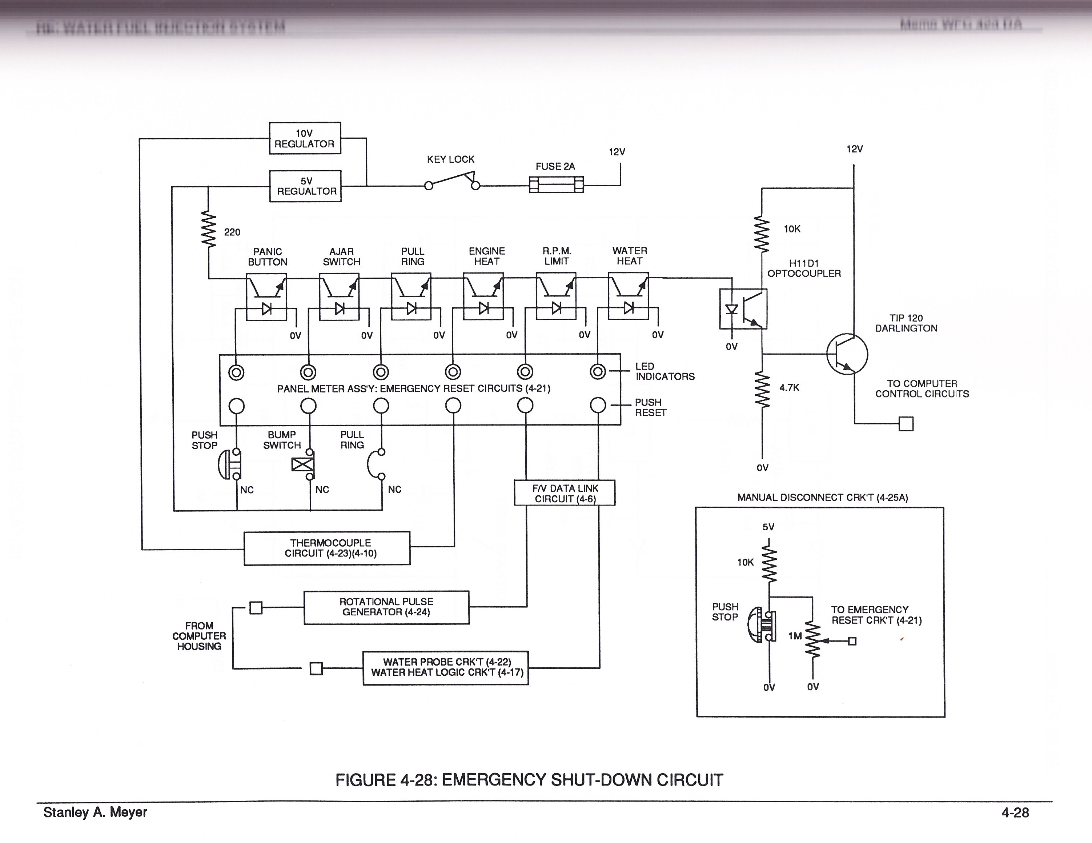
#### Emergency Shutdown Circuit
[](https://stanslegacy.com/uploads/images/gallery/2024-03/yDPM21qysaP0NtvL-image-1710803164189-06-02.png)
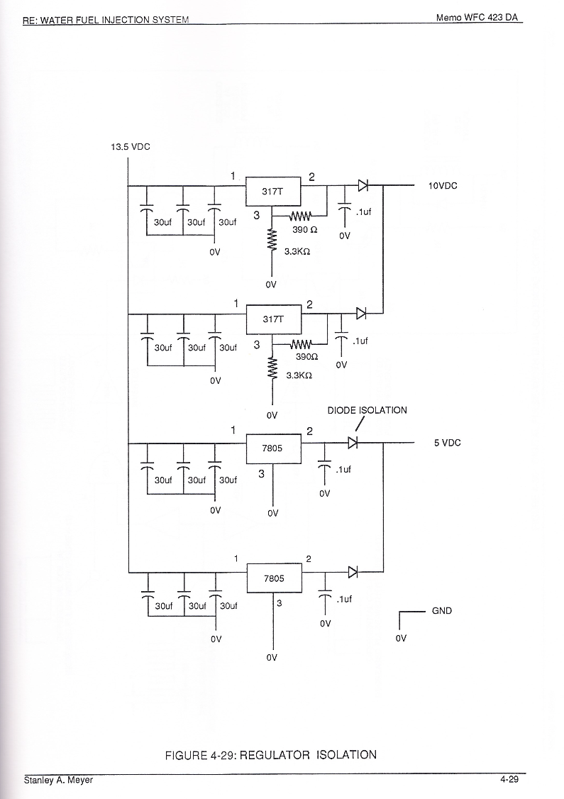
#### Regulator Isolation
[](https://stanslegacy.com/uploads/images/gallery/2024-03/zecXh7p3HfIPsMYz-image-1710803186648-06-24.png)
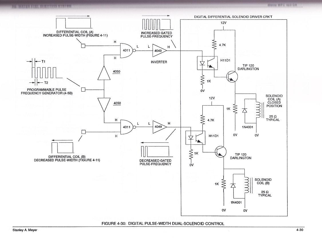
#### Digital Pulse-Width Dual-Solenoid Control
[](https://stanslegacy.com/uploads/images/gallery/2024-03/WjiIVphZ9gv1QYl6-image-1710803260345-07-38.png)
####
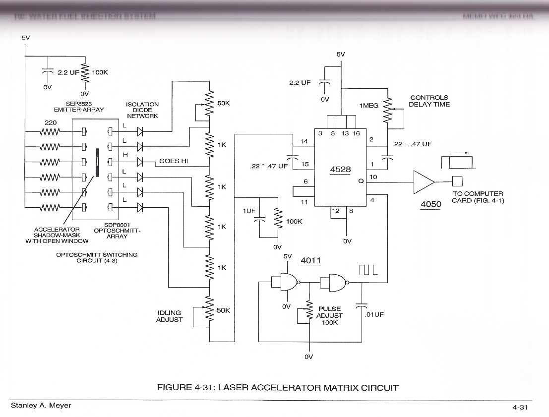
#### Laser Accelerator Matrix Circuit
[](https://stanslegacy.com/uploads/images/gallery/2024-03/w2REXIaUsHwNeSo0-image-1710803230713-07-08.png)
# WDMS Laser Acceleration Cards
> RE: WATER FUEL INJECTION SYSTEM
> Memo WFC 423 DA Gasoline Vs "Water as Fuel" :
**50 hp Internal Combustion Engine**
1ml/min gasoline consumption rate (on-road tested) @65 mph ÷25. hydrogen-fuel of water = 44.4 ml/min water flow rate ÷60 sec. = 740 ml/sec. water-fuel consumption rate@ 65m.p.h.
**Water Injection Cycle**
030, г р ÷ 60 sec. = 50 engine revolutions/sec ÷ 2 (Distributor Turn Ratio) 52 Rotor revolutions/sec x 4 Water-Fuel Injectors = 100 Injection cycles/sec.
**Thus,**
0.47 ml/sec water-fuel rate ÷ 100 injection cycles/sec. =
7.4 ul Water Droplet / injection cycle Voatlge Intensifier Circuit
40,000 volts @1ma =40 wats of applied electrical power
40 watts ÷ 12 volts battery = 3. amp/hr (current) draw capacity
00amp/hr battery ÷3. amp/hr current consumption =30.3 battery-life without recharging
Distributor Firing Sequence
25 Rotor Revolution / sec ÷ 1000 = 25ms / Rev. Water Inject-Time & applied Pulse-Voltage
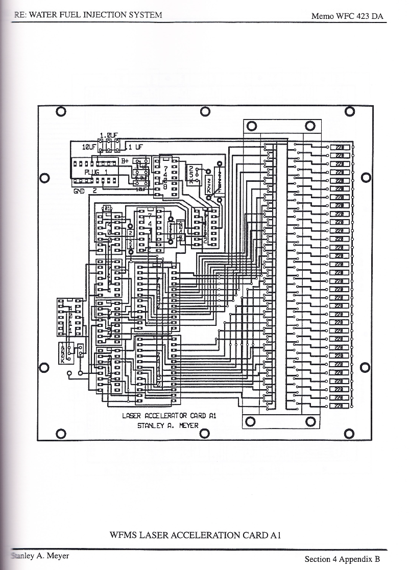
#### WFMS Laser Acceleration Card A1
[](https://stanslegacy.com/uploads/images/gallery/2024-03/f2AFxjlX6fEfT9uF-image-1710803362194-09-19.png)
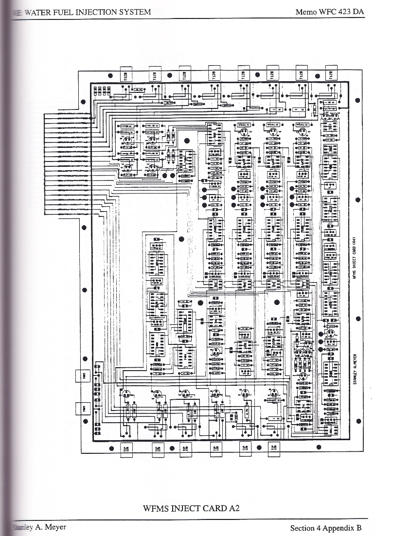
#### WFMS Inject Card A2
[](https://stanslegacy.com/uploads/images/gallery/2024-03/61TmBYIjxKTPKpCD-image-1710803402118-09-59.png)
#### WFMS Inject Card A3
[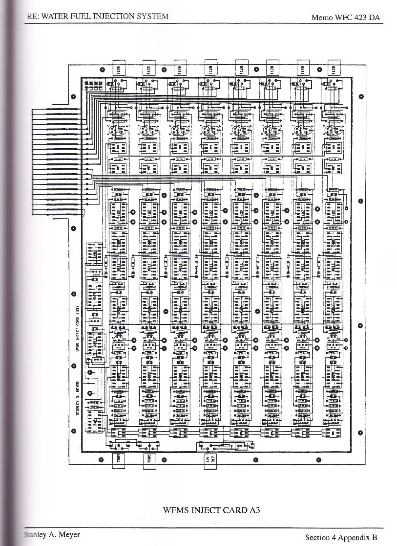](https://stanslegacy.com/uploads/images/gallery/2024-03/IaEOE8kDzBnZhgqI-image-1710803427493-10-25.png)
# Differential Air-Gas Inlet Control
[](https://stanslegacy.com/uploads/images/gallery/2024-03/RxjXI6ChYH2jwVLz-image-1710802430087-53-47.png)
#### Differential Air-Gas Inlet Control Diagram
[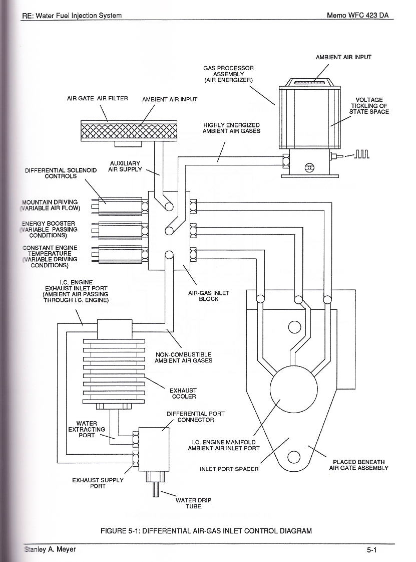](https://stanslegacy.com/uploads/images/gallery/2024-03/YUn9iPHHTrMXSU3h-image-1710803590374-13-07.png)
#### Gas Processor Assembly 2
[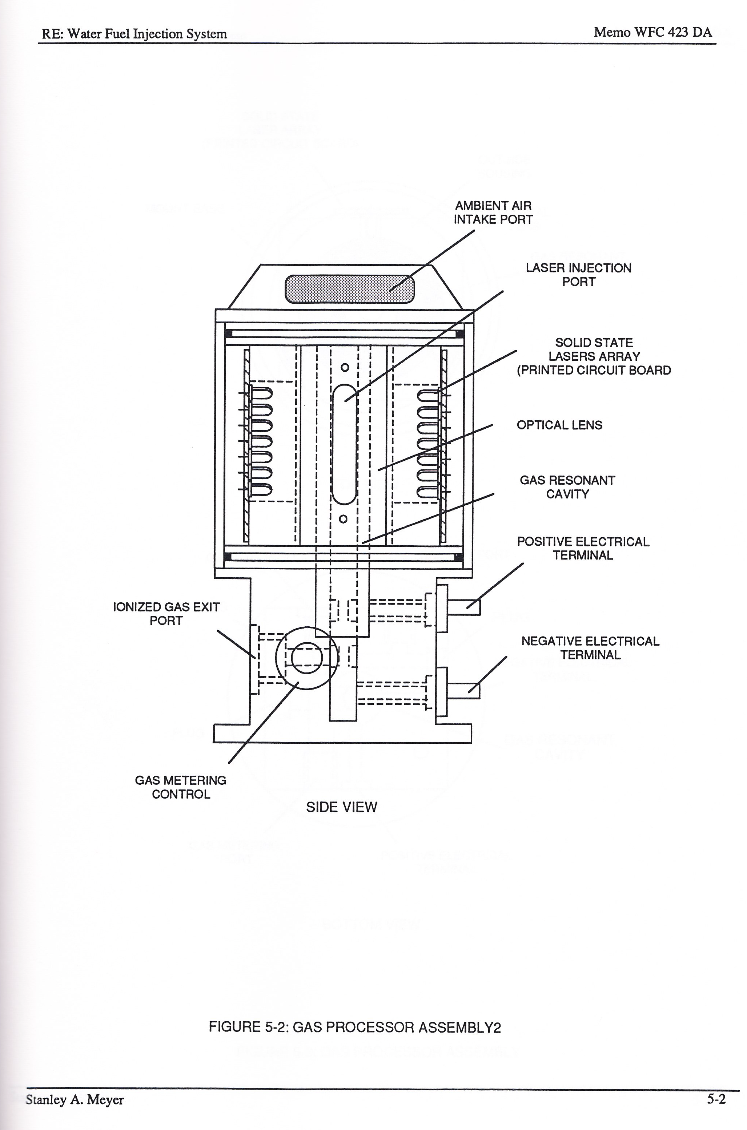](https://stanslegacy.com/uploads/images/gallery/2024-03/XbP2D2XCQQGCTAWa-image-1710803678025-14-35.png)
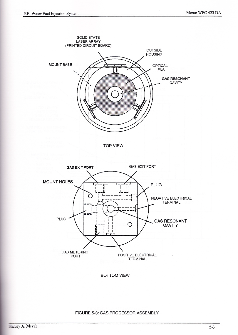
#### Gas Processor Assembly
[](https://stanslegacy.com/uploads/images/gallery/2024-03/Ry7atteKxMucf0N2-image-1710803702326-15-00.png)
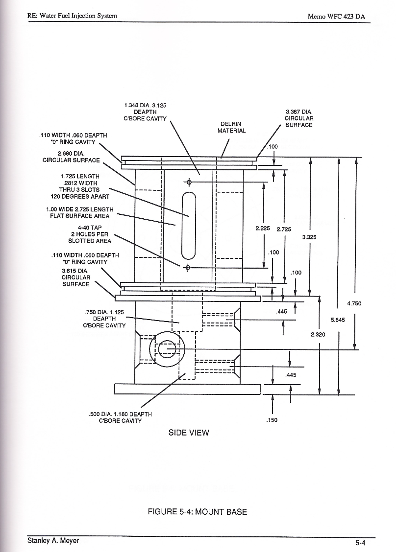
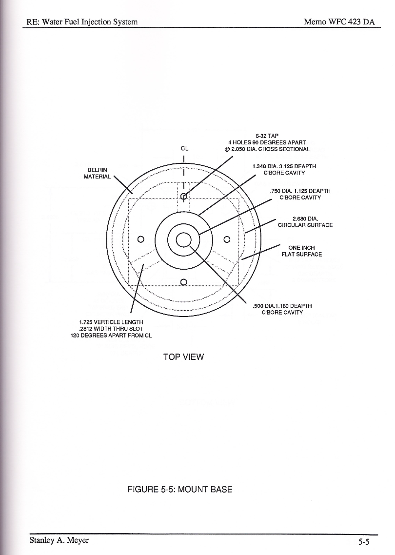
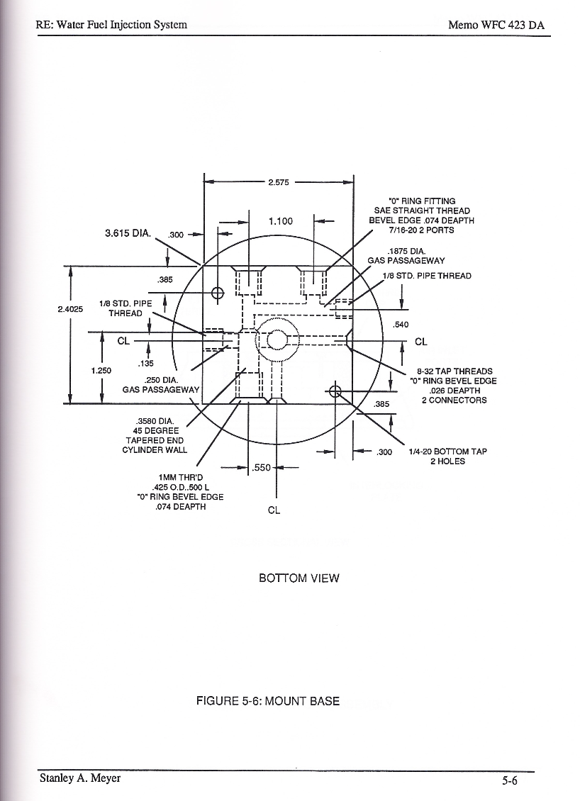
#### Mount Base
[](https://stanslegacy.com/uploads/images/gallery/2024-03/WaHOZ4GrUA4b8L3W-image-1710803723280-15-19.png)
#### Mount Base
[](https://stanslegacy.com/uploads/images/gallery/2024-03/klukDpybGQpsQP3T-image-1710803774666-16-11.png)
#### Mount Base
[](https://stanslegacy.com/uploads/images/gallery/2024-03/51zFfti0qb04auet-image-1710803798968-16-36.png)
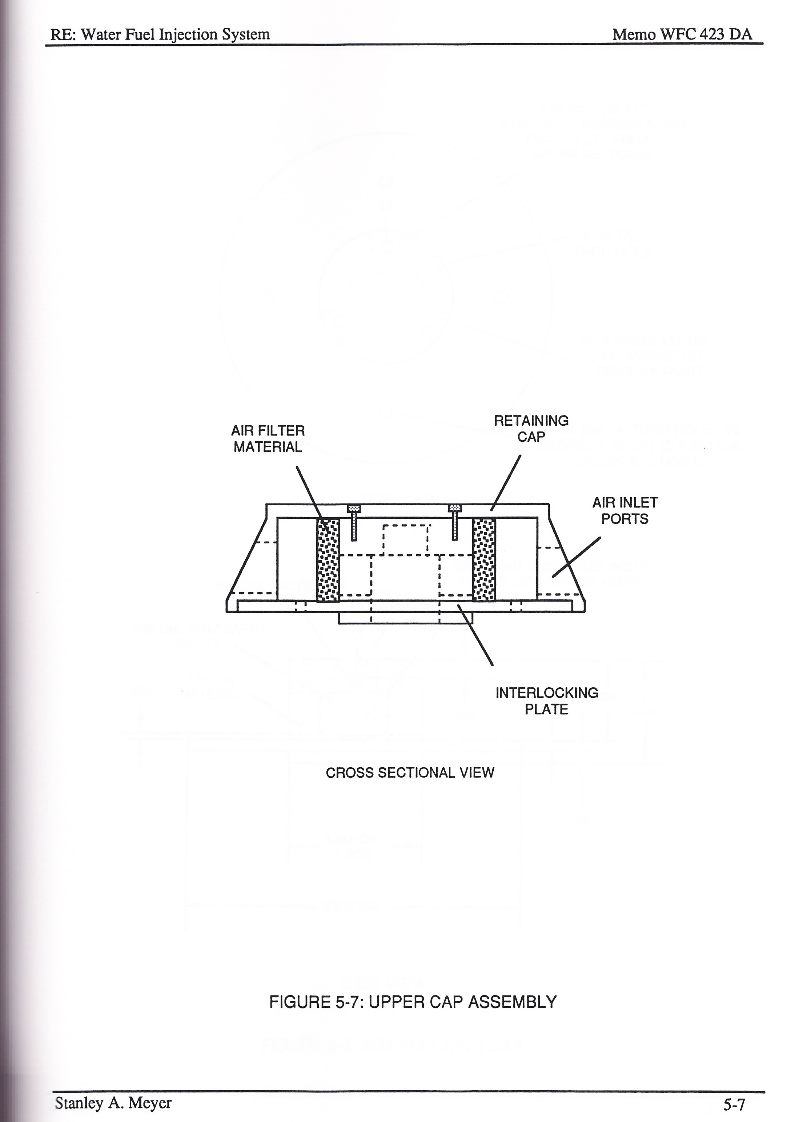
#### Upper Cap Assembly
[](https://stanslegacy.com/uploads/images/gallery/2024-03/UknDH5TehmtG9O4T-image-1710803820636-16-58.png)
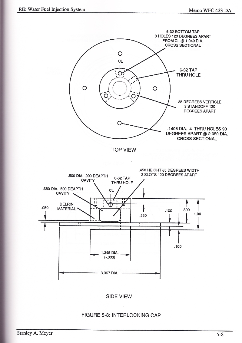
#### Interlocking Cap
[](https://stanslegacy.com/uploads/images/gallery/2024-03/qbj8gj2y42vA0m2y-image-1710803849635-17-27.png)
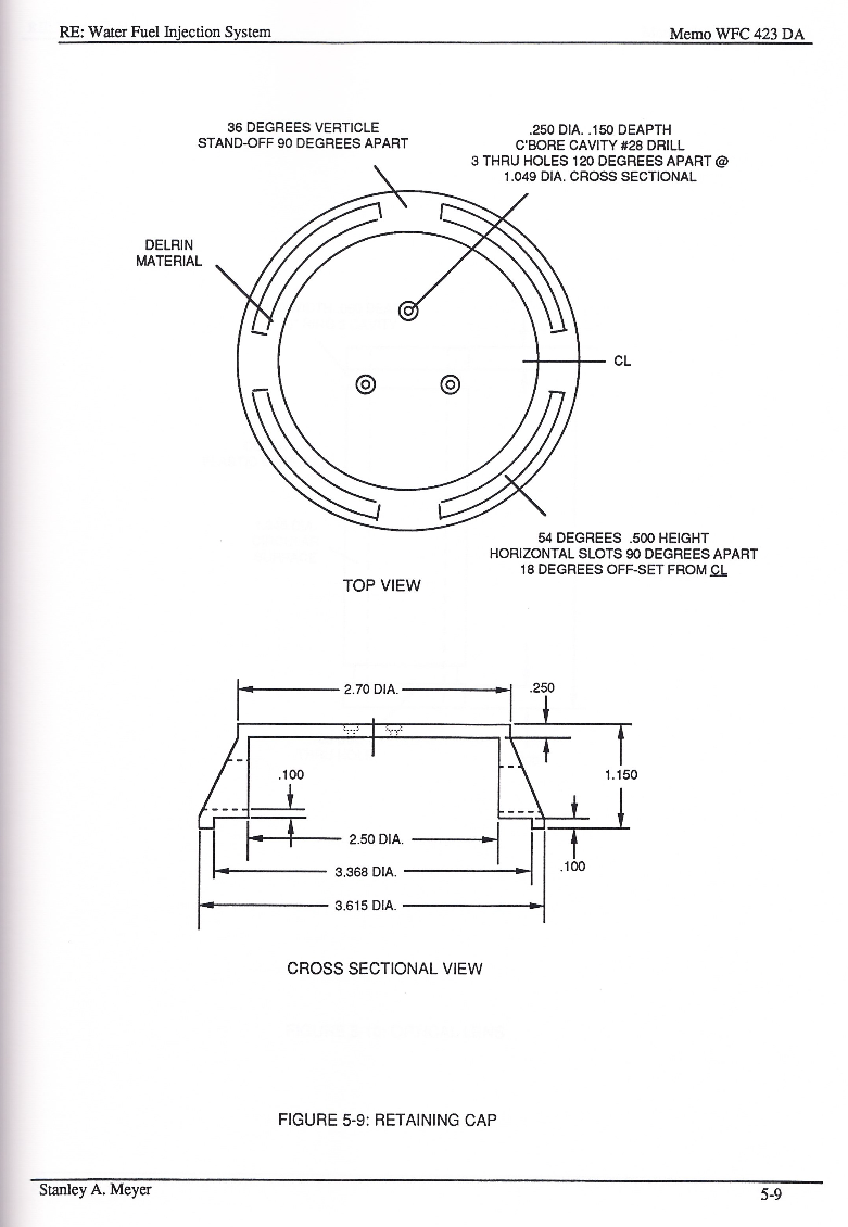
#### Retaining Cap
[](https://stanslegacy.com/uploads/images/gallery/2024-03/ydSpYnItO9LRrESi-image-1710803871754-17-49.png)
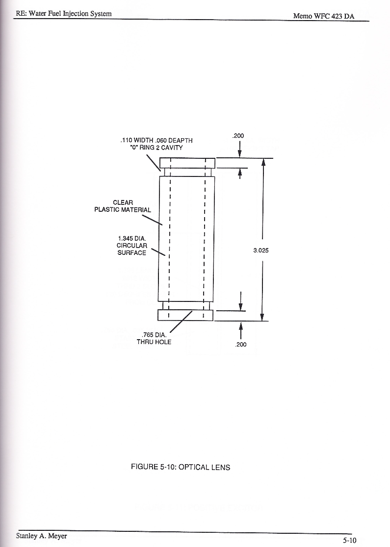
#### Optical Lens
[](https://stanslegacy.com/uploads/images/gallery/2024-03/aAUKvGW2byBSL1l5-image-1710803890443-18-08.png)
#### WFMS Gas Processor Card A4
[](https://stanslegacy.com/uploads/images/gallery/2024-03/ExF4NfCeIh9hQXQG-image-1710803487518-11-25.png)
# Water Fuel Injector (Taper Resonant Cavity Chamber)
#### Taper Resonant Cavity Chamber
To set up, trigger, and perform **Hydrogen Fracturing Process** (390) of Figure (3-42) (see [WFC Memo 422 DA](https://stanslegacy.com/books/the-birth-of-new-technology/chapter/wfc-422da-wfc-hydrogen-gas-management-system "WFC 422DA - WFC Hydrogen Gas Management System")) **gas ignition stage** (100) of Figure (6) ...
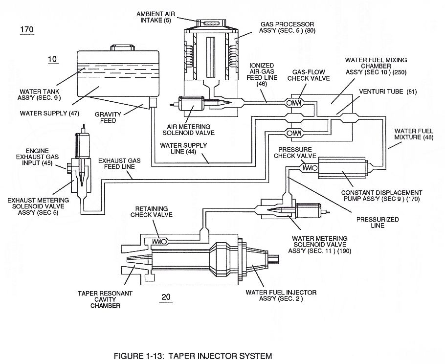
releasing thermal explosive energy (gtnt) via **flame projection** (16) of Figure (3B) as to Figure (14), **Water Fuel Injection System** (10) of Figure (1) as to (170) of Figure (13) incorporates and uses **Taper Resonant Cavity Chamber** (180) of Figure (14) to enhance operational parameters of **Hydrogen Fracturing Process** (100) of Figure (6) being stimulated to activation by **opposite electrical voltage fields** (49/51) of Figure (3B) as to (180) of Figure (14).
| **flame projection** (16) of Figure (3B)
[](https://stanslegacy.com/uploads/images/gallery/2024-03/lEKSdZZG5WiUvmUW-image-1711235079510-04-35.png)
| **Water Fuel Injection System** (10) of Figure (1)
[](https://stanslegacy.com/uploads/images/gallery/2024-03/5G6eSwP2K8xbGh7N-image-1711239688578-21-26.png)
| (170) of Figure (13)[](https://stanslegacy.com/uploads/images/gallery/2024-03/OUpVseXIiARHRB16-image-1711239747353-22-24.png) |
[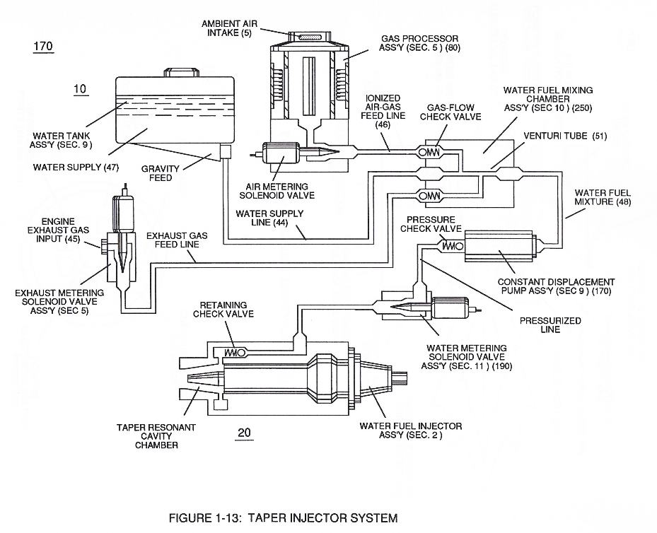](https://stanslegacy.com/uploads/images/gallery/2024-03/mMcNeHkTnD6lnRzb-image-1711239975992-26-13.png)In like manner, **water supply** (10) of Figure (170), **non-combustible gases** (45) (*Engine Exhaust gases*), and **ambient air ionized gases** (46) (*air gases having missing electrons*) are uniformly intermixed when moving into, passing through and beyond **fluid mixing chamber** (250) of Figure (13) by way of **venturi tube-cavity** (51)...
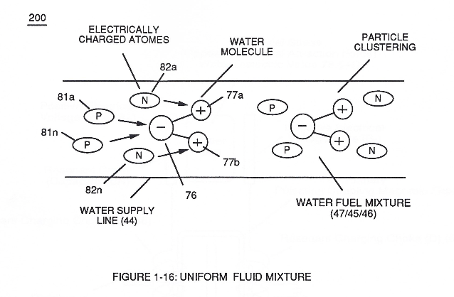
allowing water fuel mixture (47/45/46) (48) to be particle aligned by opposite electrostatically charged atoms
...positive charged gas particles (81a xxx 81n) being directed to and attached to negative charged oxygen atom (76) of water molecule (47);
while, during the same interim period of time, **negative charged gas particles** (82a xxx 82n) being directed onward to and affix themselves to **positive charged hydrogen atoms** (77a / 77b), as illustrated in (200) of Figure (16).
[](https://stanslegacy.com/uploads/images/gallery/2024-03/5phF31y6vSDzGYIk-image-1711240076581-27-54.png)
The resultant water fuel-mixture (48) is, now, pressurized up to and beyond 125 lbs of fluid-pressure by **Fluid Displacement Pump** (170) of Figure (13), as before, to cause and form water fuel-droplets (48a xxx 48n) when water fuel (48) enters into, passes through and beyond spray ports (41a xxx 41n) forming **Quenching Disc Structure** (190) of Figure (15).
| **Fluid Displacement Pump** (170) of Figure (13)
[](https://stanslegacy.com/uploads/images/gallery/2024-03/Uc94Wno727HBNfNf-image-1711241901925-58-18.png)
| Quenching Disc Structure (190) of Figure (15)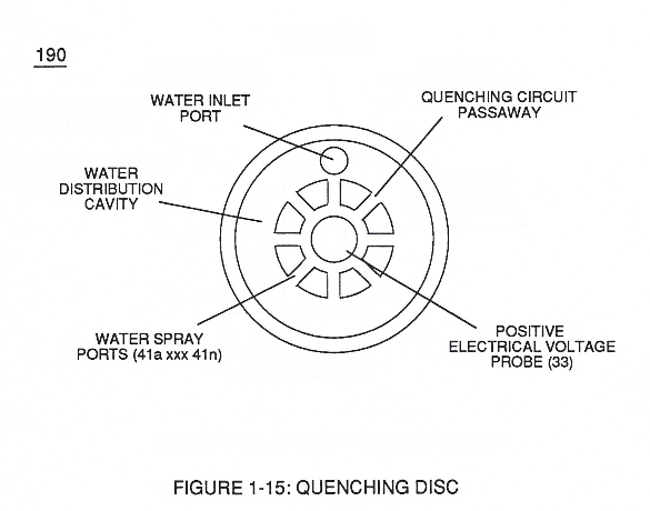 |
The injected **water fuel-droplets** (48a xxx 48n), now, surrounds outer surface area of exposed **positive probe** (33) while entering into **Taper Resonant Cavity** (180), as illustrated in (70) of Figure (3B) as to Figure (14).
Once water fuel-droplets (xxx 48n) fully occupies open space cavity (**Resonant Cavity Zone**) (35) and then exposed to applied pulsating opposite electrical voltage fields (49/51) of voltage wave form (280) of Figure (17), the electrically stimulated water fuel droplets (48a xxx 48n) are subjected to release thermal explosive energy (gtnt) (16) undergoing **Electrical-Resonant** in a sequential manner:
[](https://stanslegacy.com/uploads/images/gallery/2024-03/pHJJMAHMYDulX5HH-image-1711242198362-03-15.png)
By **first**, separating water molecule (47) into its component gases (oxygen 76 / hydrogen 77a - 77b) by way of the Electrical Polarization Process (160) of Figure (25) ([WFC Memo 422 DA](https://stanslegacy.com/books/the-birth-of-new-technology/chapter/wfc-422da-wfc-hydrogen-gas-management-system "WFC 422DA - WFC Hydrogen Gas Management System"));
[](https://stanslegacy.com/uploads/images/gallery/2024-03/LoJA7Rs0RRNkGufD-image-1711240326284.png)
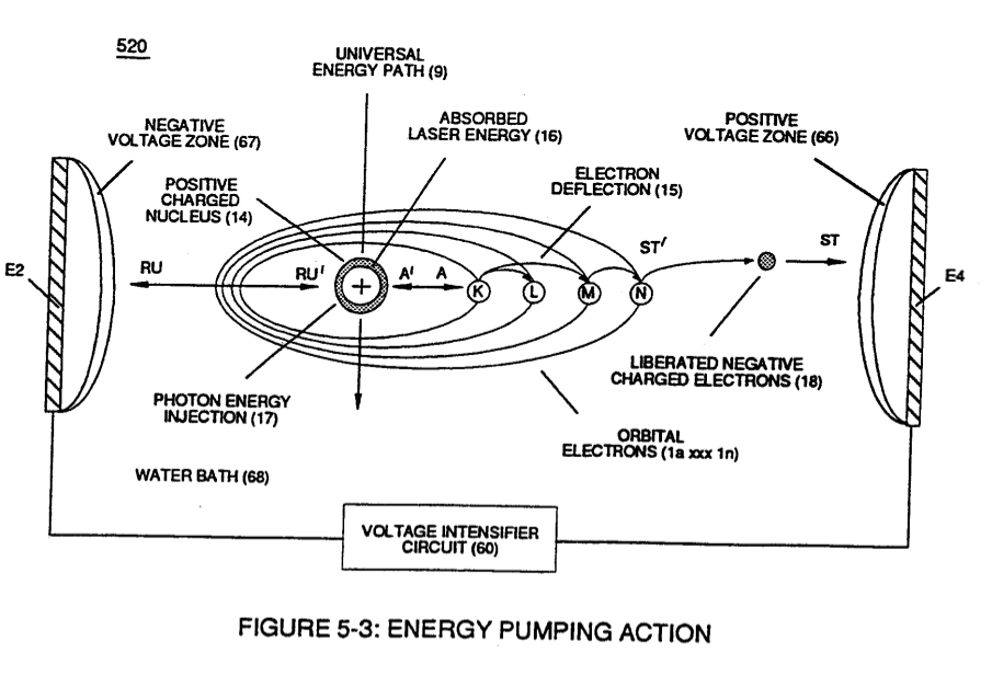
**secondly**, by electrically attenuating the electrical-forces of the newly formed and liberated combustible gases (76, 77a - 77b) via Energy-Priming Process (520) (see [WFC Memo 424](https://stanslegacy.com/books/the-birth-of-new-technology/chapter/wfc-424-atomic-energy-balance-of-water "WFC 424 - Atomic Energy Balance of Water") titled "Atomic Energy Balance of Water);
[](https://stanslegacy.com/uploads/images/gallery/2024-03/gX9NnG55mQj0YygS-image-1711240273862.png)
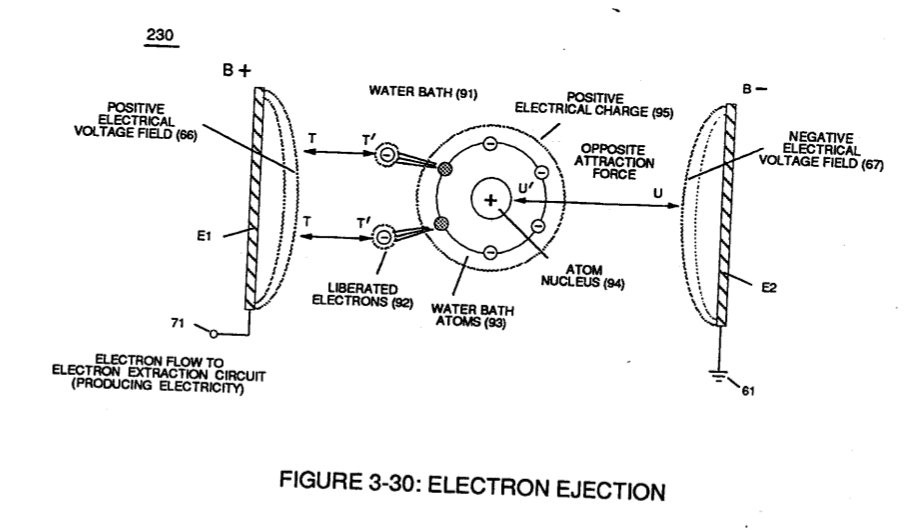
**thirdly**, by ionizing the released combustible gases by way of **Electron Ejection Process** (230) of Figure (29) ([WFC Memo 422 DA](https://stanslegacy.com/books/the-birth-of-new-technology/chapter/wfc-422da-wfc-hydrogen-gas-management-system "WFC 422DA - WFC Hydrogen Gas Management System")), as further illustrated in (80) of Figure (4);
| **Electron Ejection Process** (230) of Figure (29)
| (80) of Figure (4)
[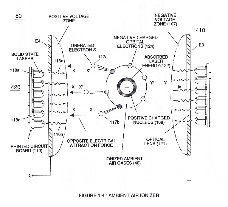](https://stanslegacy.com/uploads/images/gallery/2024-03/sxDuDQrTfViKX2st-image-1711240439701-33-56.png)
|
[](https://stanslegacy.com/uploads/images/gallery/2024-03/pHJJMAHMYDulX5HH-image-1711242198362-03-15.png)and **finally**, spark-ignite the highly destabilized combustible gases (laser primed combustible gases having missing electrons) by electrostatic discharge (kinetic energy agitation), as further exemplified in (280) of Figure (17);
all sequential gas priming functions occurring progressively in an instant of time.
Subsequent and repetitive formation of applied **gated electrical voltage pulse-train** (210a xxx 210n) of Figure (17) to continued in-flow of **water fuel droplets** (48a xxx 48n) not only sustains and maintains **Hydrogen Fracturing Process** (100) of Figure (6) but, also, regulates **Thermal Explosive Energy** release (16a x 16n) of Figure (14) by attenuating applied voltage amplitude (xxx VL xxx), as graphically shown in Figure (20F) ([WFC Memo 420](https://stanslegacy.com/books/the-birth-of-new-technology/chapter/wfc-420-hydrogen-fracturing-process "WFC 420 - Hydrogen Fracturing Process")).
| **Hydrogen Fracturing Process** (100) of Figure (6)
[](https://stanslegacy.com/uploads/images/gallery/2024-03/JqeitiAp4qURSnQb-image-1711239500177-18-17.png)
| **Thermal Explosive Energy** release (16a xxx 16n) of Figure (14)
[](https://stanslegacy.com/uploads/images/gallery/2024-03/lEKSdZZG5WiUvmUW-image-1711235079510-04-35.png)
|
This further increase in voltage amplitude (xxxx VL) simply exerts a greater magnitude of opposite **Electrical-Stress** (SS'-RR') of Figure (25) (TT' - UU') of Figure (29) ([WFC Memo 422 DA](https://stanslegacy.com/books/the-birth-of-new-technology/chapter/wfc-422da-wfc-hydrogen-gas-management-system "WFC 422DA - WFC Hydrogen Gas Management System")) across combustible gas atoms (76, 77a - 77b)
which, in turns, ejects a greater number of electrons while preventing the formation of the water molecule (390) of Figure (41) ([WFC Memo 422 DA](https://stanslegacy.com/books/the-birth-of-new-technology/chapter/wfc-422da-wfc-hydrogen-gas-management-system "WFC 422DA - WFC Hydrogen Gas Management System")) during thermal gas-ignition (180) of Figure (14).
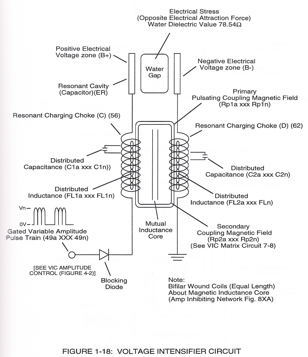
Voltage Intensifier Circuit (220) of Figure (18) allows Electrical-Stress variation (SS' = RR' / TT' = UU') since **voltage Intensifier Circuit** (220) inhibits electron-flow (amp restriction) into voltage triggering process (210) of Figure (17) as to (100) of Figure (6).
[](https://stanslegacy.com/uploads/images/gallery/2024-03/UbQQXtm822UJY1my-image-1711238945929-09-03.png)
| voltage triggering process (210) of Figure (17)
[](https://stanslegacy.com/uploads/images/gallery/2024-03/pHJJMAHMYDulX5HH-image-1711242198362-03-15.png)
| (100) of Figure (6) |
Electron restriction while varying voltage intensity (Va = Vn) is accomplished by performing several functions simultaneously:
Incoming **pulse-train** (210a xxx 210n) is adjusted to "tune-in" to the Dielectric Properties of Water (47) which allows Resonant Action (see [WFC Memo 424](https://stanslegacy.com/books/the-birth-of-new-technology/chapter/wfc-424-atomic-energy-balance-of-water "WFC 424 - Atomic Energy Balance of Water"), once again) to occur since the Dielectric property of water (*78.54 value*) becomes a integral part of **Electronic Circuit** (110) of Figure (7) as to (220) of Figure (18)
| **Electronic Circuit** (110) of Figure (7)
[](https://stanslegacy.com/uploads/images/gallery/2024-03/aEKWjdeQv4j5D9sz-image-1711246045987-07-24.png)
| (220) of Figure (18)
[](https://stanslegacy.com/uploads/images/gallery/2024-03/UbQQXtm822UJY1my-image-1711238945929-09-03.png)
|
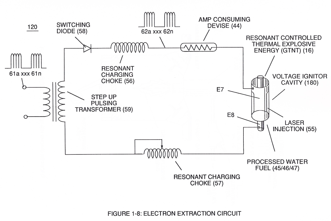
... forming a capacitor (E7 / E8) in series with Resonant Charging Chokes (56/57) placed on opposite sides of Resonant Cavity Zone (35) as to Figure (7) and (8) . . . forming a Resonant Pulsing Circuit (110) of Figure (7) with step-up **Pulsing Transformer** (33/36), as shown in (220) of Figure (18).
Adjusting Pulse-train (210a xxx 210n) in such a way as to allow pulse off-time (T2) to be synchronized with collapsing and re-formation of electromagnetic field coupling across pulsing transformer (52/53) to produce unipolar pulse frequency (T1a xxx T1n), as illustrated in (220) of Figure (18) as to Figure (17).
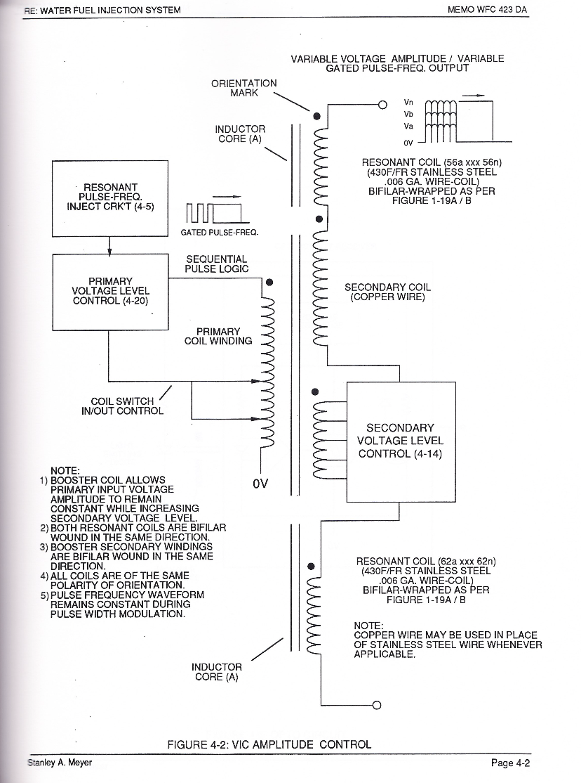
Pulse on-time (T1) having a predetermined **constant voltage level** (xxx VL xxx) is adjusted to maximize transference of electromagnetic energy to **Secondary Coil** (53) during pulsing operations.
The resultant and newly formed **gated** **Resonant Pulse-train** (T1 + T2a xxx T1 + T2n) (58) voltage amplitude (Vo xxx Vn) is, now, attenuated by **Sequential Voltage Amplitude Control Circuit** (59) once step up **Secondary Coil** (53) produces a higher voltage level (xxxVL) above incoming **pulse-train** (210) since **Secondary Coil** (53) has a greater number of turns of wire.
| [](https://stanslegacy.com/uploads/images/gallery/2024-03/ENk0b7D7uh9mDVXX-image-1711236926123-35-23.png) | [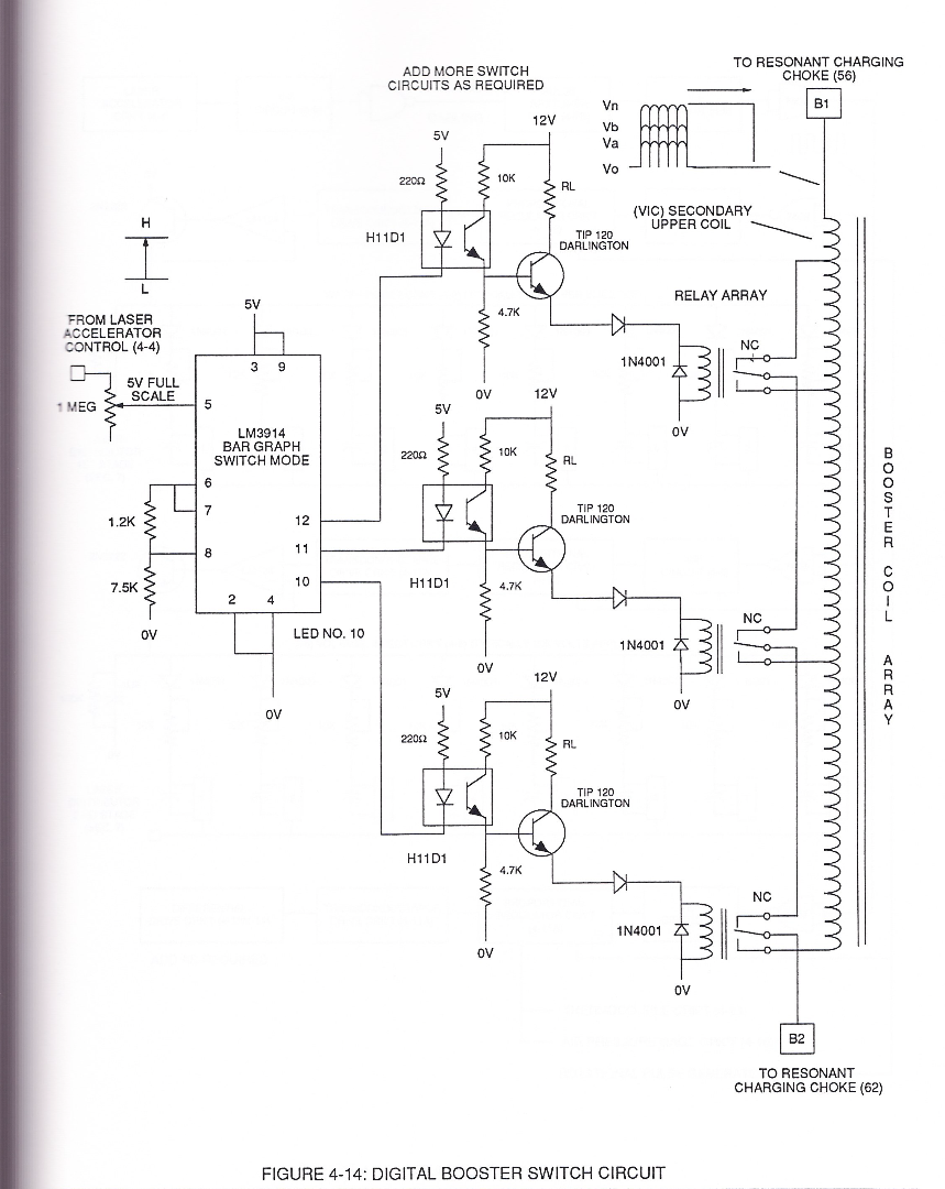](https://stanslegacy.com/uploads/images/gallery/2024-03/2AJ8bEqLZFOJQtAM-image-1711238092887-54-49.png)
|
**Sequential Switch Circuit** (59) simply switches in and out **Booster Pickup Coils** (61a xxx 61n) in series electrical hookup with **Secondary Coil** (53) output to elevate voltage intensity across Resonant Charging Chokes (56/57).
Forming Resonant Charging Chokes (56/57) by using Stainless Steel Electro-Inductance wire-material (430F / T304 or equivalent) which, when electrically pulsed transmits voltage intensity while restricting amp flow during Resonant Pulsing operations. Together, the resistive valve of Stainless Steel wire-coil (56/57) and its inductance generated electromagnetic field (62) of Figure (19) opposes the movement of electrons since the dielectric valve of wire-coils (56/57) inhibits electron exchange while the generated inductance field (62) locks onto the electromagnetic field of the electrons ...generated coil inductance field (62) being greater in electromagnetic... \[ends abruptly...\]
| [](https://stanslegacy.com/uploads/images/gallery/2024-03/ItHbfV0yw5rt3wzS-image-1711238896182-08-12.png)
| [](https://stanslegacy.com/uploads/images/gallery/2024-03/9fhLQE7R6ZHcUQyz-image-1711238904577-08-22.png) |
#### The Following Page 1-7 was not available
The "**Plus Factor**" is that induce **external** **electromagnetic field** (63/64) across **Resonant coil-Tap** (67) increases voltage intensity (*voltage potential*) still further rather than diminishes peak voltage potential due to resistive valve of the stainless steel wire.
In other words, the inductance and capacitance values of **stainless steel induction coil** (56/57) bypasses voltage drop across its resistive load (ohmic valve of wire).
This induced voltage phenomenon encourages and therefore prevents resonant **pulse frequency** (58) from being impaired or altered while being electrically transmitted to **Resonant Cavity** (180) of Figure (14) via electrical tabs (71) and (72) of Figure (14).
[](https://stanslegacy.com/uploads/images/gallery/2024-03/lEKSdZZG5WiUvmUW-image-1711235079510-04-35.png)
# Funneling Effect
[](https://stanslegacy.com/uploads/images/gallery/2024-03/O2XDg5jk3UxGd1TD-image-1711234955125-02-31.png)Enhancement of the operational parameters of **Hydrogen Fracturing Process** (100) of Figure (6) is further exemplified when incoming **Resonant voltage-wave** (58) of Figure (18) electrically transmitted across **Resonant Cavity Zone** (35) during water injection cycle...
causing **Resonant Cavity Zone** (35) to function and perform as a **voltage wave-guide** (86) of Figure (14) since the gradual decrease in cross-sectional circumference area (85) of Figure (14) is in linear progression ... reducing both voltage surfaces areas (83/84) in parallel space relationship from larger segmental area (85a) to smaller segmental area (85n).
[](https://stanslegacy.com/uploads/images/gallery/2024-03/lEKSdZZG5WiUvmUW-image-1711235079510-04-35.png)
[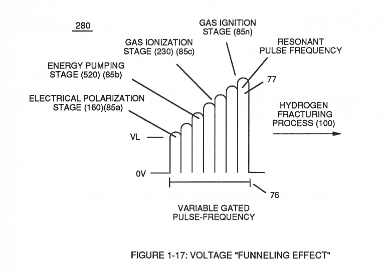](https://stanslegacy.com/uploads/images/gallery/2024-03/cZL77j1fmGg8PZwq-image-1711235293362-08-10.png)This resultant "**Funneling Effect**" (260), now, allows voltage amplitude (Vn) **wave-form** (58) to travel the length of Resonant Cavity Zone (35) from **Start-Point** (85a) to **End-Point** (85n) increasing voltage intensity (xxx VL = Vn) as parallel voltage surfaces (83/84) diminishes in size relationship (85a ~ 85n), as illustrated in (210) of Figure (17).
This "progressive" increase in voltage intensity (VL ~= Vn) due to the "**Funneling Effect**", now, allows several gas processing functions to occur in a instant of time:
Voltage amplitude level VL of **Pulse-wave** (58) is predetermined (*20,000 V.D.C. typically)* to start and cause **Electrical Polarization Process** (160) at a relative rapid rate of gas production at segmental point (85a) when voltage point (VL xx Va) is reached.
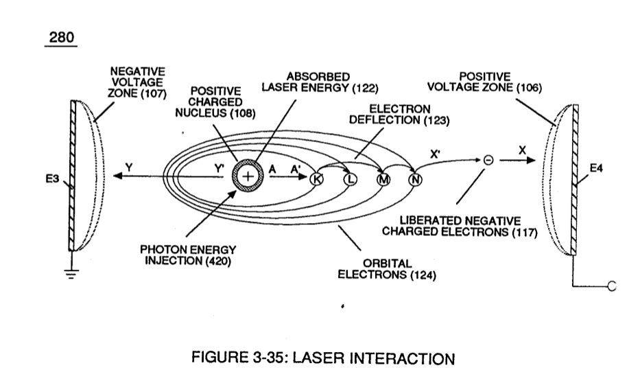
As voltage intensity increases (VL x Va x Vb) onward segmental point (85b), **Energy Pumping Action** (520) of Figure (4-3) ([WFC Memo 424](https://stanslegacy.com/books/the-birth-of-new-technology/chapter/wfc-424-atomic-energy-balance-of-water "WFC 424 - Atomic Energy Balance of Water")) as to (280) of Figure (34) ([WFC Memo 422 DA](https://stanslegacy.com/books/the-birth-of-new-technology/chapter/wfc-422da-wfc-hydrogen-gas-management-system "WFC 422DA - WFC Hydrogen Gas Management System")) is activated to peak performance levels.
| (520) of Figure (4-3)
[](https://stanslegacy.com/uploads/images/gallery/2024-03/gQbpGVKKKqmEbEYT-image-1711236158134-22-35.png)
| (280) of Figure (34)
[](https://stanslegacy.com/uploads/images/gallery/2024-03/HYSxIlsAQa2ancBF-image-1711236265839-24-23.png)
|
At segmental point (85c) voltage intensity (VL x Va x Vb x Vc) is increased sufficiently enough to propagate **Gas Ionization Process** (230) of Figure (3-30) ([WFC Memo 422 DA](https://stanslegacy.com/books/the-birth-of-new-technology/chapter/wfc-422da-wfc-hydrogen-gas-management-system "WFC 422DA - WFC Hydrogen Gas Management System")).
[](https://stanslegacy.com/uploads/images/gallery/2024-03/pe6afqhEDgTyKAXl-image-1711236372677-26-10.png)
At termination point (85), voltage intensity (VL x Va x Vb x Vc x Vn) is, now, increased to the point to cause **Gas Ignition** as **Combustible Gas Atoms** (76, 77a - 77b) which are, then, expelled from **Gas Nozzle Port** (87) of Figure (14) under dynamic pressure to allow **thermal gas expansion** (16) ... releasing thermal explosive energy (gtnt) beyond and away from **Resonant Cavity Chamber** (180), as illustrated in Figure (14).
[](https://stanslegacy.com/uploads/images/gallery/2024-03/lEKSdZZG5WiUvmUW-image-1711235079510-04-35.png)
To prevent pre-ignition of gases traveling toward **Exit-Port** (87), **Resonant Cavity** (35) open space (open resonant cavity) parallel dimension between positive voltage surface (82) and negative voltage surface (83) is small enough (typically .010 or so) to function as a **Quenching Circuit**, as illustrated in Figure (24SD) (missing image) ([WFC Memo 420](https://stanslegacy.com/books/the-birth-of-new-technology/chapter/wfc-420-hydrogen-fracturing-process "WFC 420 - Hydrogen Fracturing Process")).
To increase energy levels (16a xxx 16L = 16n) of **Hydrogen Fracturing Process** (100) as to (390), even further, simply switch-on additional Booster Coils (61a x 61L - 61n) in sequential order to increase voltage intensity (VL ~ Vn ~ Vm) to higher magnitude of "**Electrical Force**" (Vma xxx Vmn) which is due to the inductance/capacitance values of each succeeding coil-structure (61a x 61n) forming **Booster coil-Assembly** (250), as illustrated in (240) of Figure (20).
| [](https://stanslegacy.com/uploads/images/gallery/2024-03/ENk0b7D7uh9mDVXX-image-1711236926123-35-23.png) | [](https://stanslegacy.com/uploads/images/gallery/2024-03/2AJ8bEqLZFOJQtAM-image-1711238092887-54-49.png) |
To return or lower Voltage Intensity (xxx Vmn) to **Secondary Voltage Level** (71), once again, inductance **core-slug** (73) (magnetic core material) advances (*via solenoid Control 74*) toward, passes through inside **coil-wrap** (250) in linear manner to "Switch-Off" each adjacent coil-stage (61a xxx 61n) by "**Shunting**" or "**Redirecting**" induced voltage intensity (Vmn xxx Vma) to its respective electrical out-put leads (72n - 72c - 72b - 72a), as shown in Figure (20).
This "**Shunting Effect**" occurs when the magnetic field strength of each individual **coil-structure** (61) (*being electrically energized*) induces and forms magnetic **core-field** (75) which opposes and stops current flow within the exposed coil-stage (61a-61b-61c-61n).
This resultant "**Shunting Effect**", now, allows voltage intensity (Vma = Vmn) to be placed across **Resonant Cavity Zone** (35) to not only compensate for water impurity that might alter the operational parameters of **Hydrogen Fracturing Process** (100) as to (390) but, also, provide "Instant" "Power-Boost" when needed.
| [](https://stanslegacy.com/uploads/images/gallery/2024-03/lEKSdZZG5WiUvmUW-image-1711235079510-04-35.png) | [](https://stanslegacy.com/uploads/images/gallery/2024-03/Qk1Jl0AL2SdmIEMn-image-1711237351260.png) |
The established "Power Boost" energy level (16a xxx 16n) is changeable, however, by, simply, electrically moving or displacing (back and forth movement) **Core-Slug** (73) to another stop-location (72)... adjusting energy-level (16a xxx) on demand.
In alternate form, **Core-Slug** (73) is replaced by a series of **Choke Coils** (77a xxx 77n) arranged in such a way as to increase voltage Intensity (Voltage Pulse Amplitude) (VL ~ Vn xxx) digitally by sequentially switching-on / switching -off Choke Coils (77a xxx 77n) to allow applied Voltage Intensity (VL ~ Vn xxx) to be placed across **Voltage Expander Coils** (78a xxx 78n) in direct relationship to electrically energized shunt-coil (76).
For example, as adjacent **Shunt-Coil** (76b) is switch-on while, simultaneously, **Choke Coil** (76a) is switch-off by **Electronic Switch Circuit** (79), Voltage Intensity (VL ~ Vn xxx) is increased due to inductance / capacitance of **Voltage Expander Coil** (78a) which is, now, added to **Electrical Circuit** (250) by electrical pathway (82a) since **electromagnetic coupling field** (76b) prevents electron flow to cause open circuit (82b)...
(missing content)
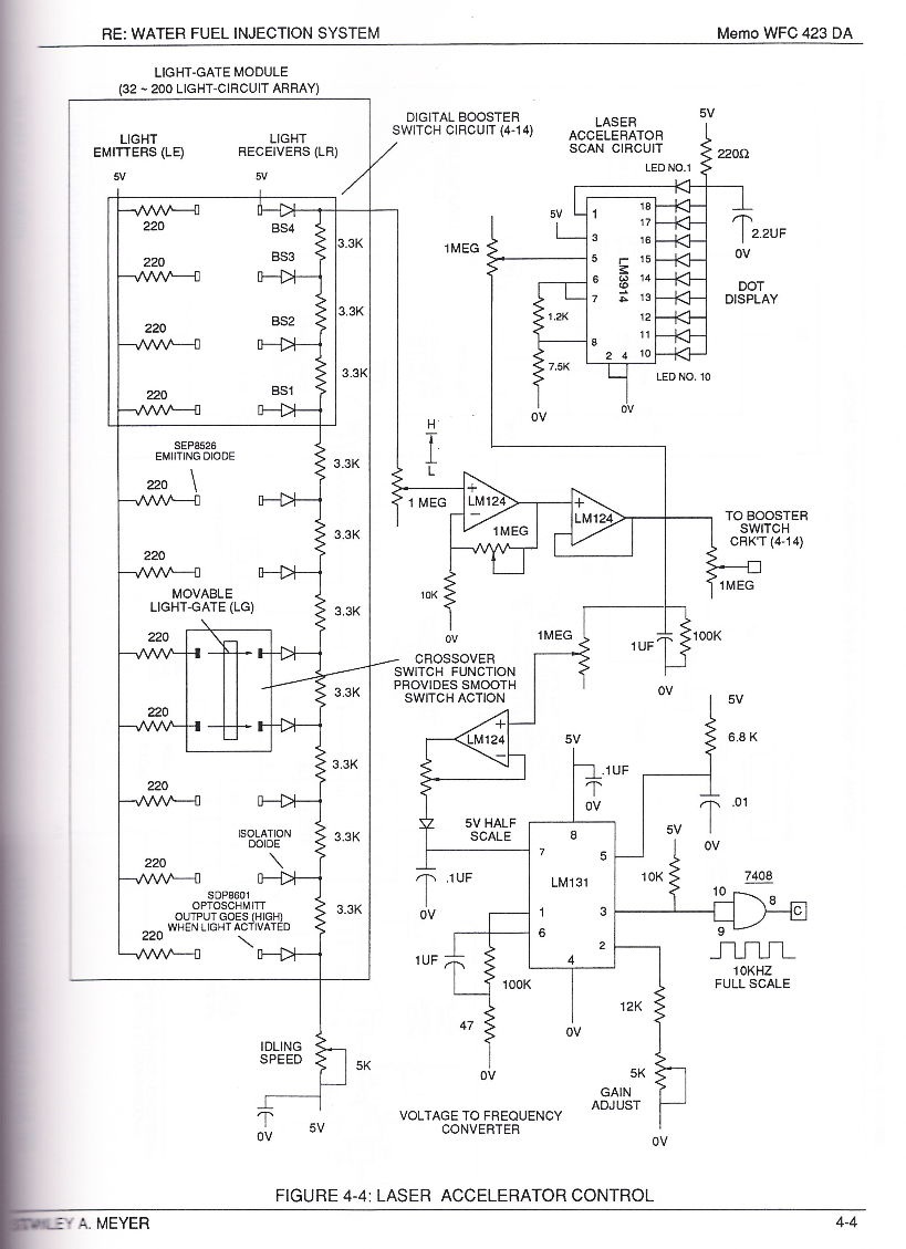
thereby establishing **Voltage Level Logic Function** (260) which is electronically transferable in sequential order (260a xxx 260n) by **Laser Acceleration Control Circuit** (4-4) of (220) of Figure (18).
[](https://stanslegacy.com/uploads/images/gallery/2024-03/Xfkuluj5Fro9DYEl-image-1711238220068-56-57.png)
thereby, attenuating voltage amplitude (voltage intensity) beyond **Secondary Coil** (53) **voltage levels** (71), as illustrated in (220) of Figure (18).
Attenuating variable voltage amplitude (72a xxx 72n) in conjunction with incoming **gated pulse-train** (210a xxx 210n), now, expands **gated pulse width** (76a xxx 76n) as voltage amplitudes (Vo xxx Vn) increases, forming step up voltage wave Form (77) of Figure (17).
[](https://stanslegacy.com/uploads/images/gallery/2024-03/EmNtWjdZJcIuRmXm-image-1711238704911-05-02.png)
This newly formed synchronized and repetitive dual expanding voltage wave form (77a xxx 77n) is further enhanced by "**Funneling Effect**" (260)... maximizing voltage dynamic across **Resonant Cavity** (35) always subjecting and exerting increase "**Electrical-Stress**" (SS'-RR' / TT'-UU') of opposite polarity across **Hydrogen Fracturing Process** (100 / 390) to the point of gas ignition.
[](https://stanslegacy.com/uploads/images/gallery/2024-03/Qk1Jl0AL2SdmIEMn-image-1711237351260.png)
# Amp Inhibiting Circuit Vs Voltage Enhancement
#### Amp Inhibiting Circuit Vs Voltage Enhancement
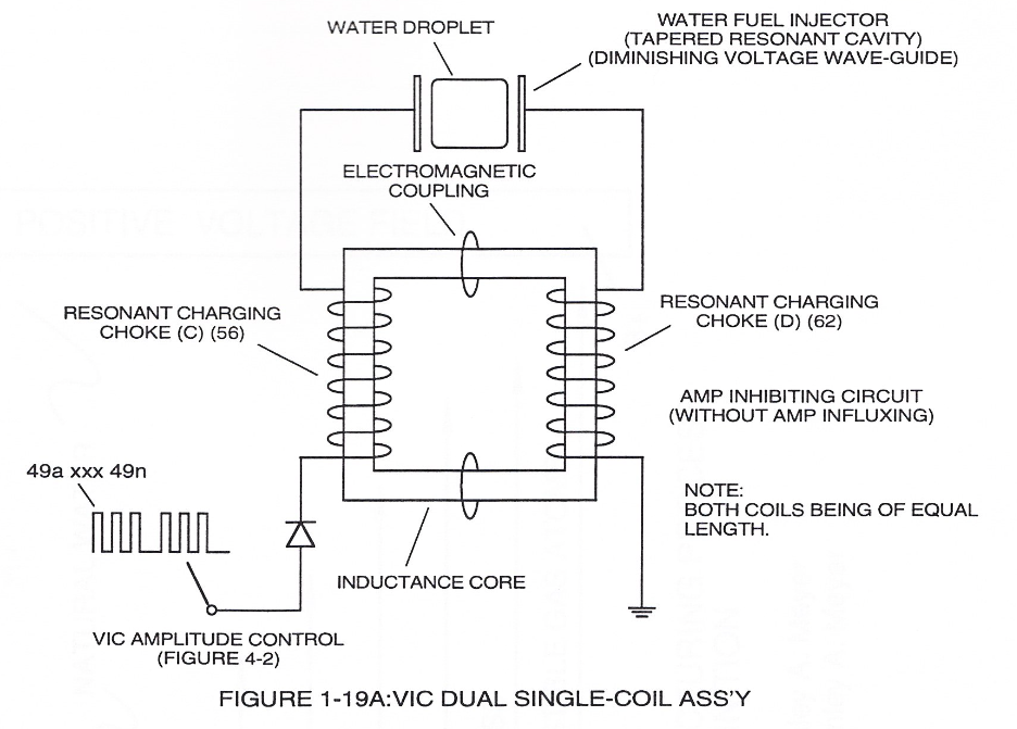
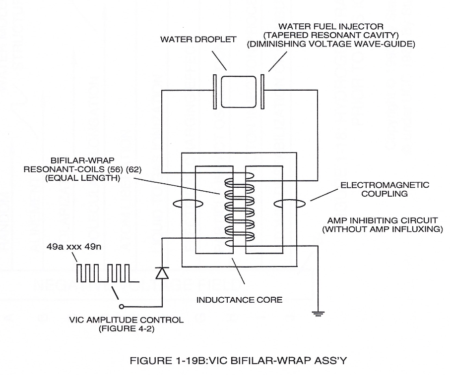
[](https://stanslegacy.com/uploads/images/gallery/2024-03/UbQQXtm822UJY1my-image-1711238945929-09-03.png)Beyond amp restricting characteristic of said Amp Inhibiting Circuit of Figure (1-18) as to VIC Dual Single-coil Assembly (Figure 1-19A) and VIC Bifilar-Wrap Coil Assembly (Figure 1-19B), the spiral-wrapped coils being paired together, also, causes voltage level enhancement beyond applied voltage input since the "**Distributed Capacitance**" (Cl xxx Cln =C2a xxx C2n) / "Distributed Inductance" (FL1a xxx FL1n = FL2a xxx FL2n) of said "Bifilar" wrapped coils encourages the compounding effect (*increasing magnetic field-strength during each pulsing cycle*) of electromagnetic field-strength (Rpla xxx Rpin = Rp2a xxx Rp2n) (*mutual induction*) when applied **Pulse-Voltage Frequency** (49a xxx 49n) passes through the positive energized **Resonant Charging Choke** (56).
[](https://stanslegacy.com/uploads/images/gallery/2024-03/i811WuUTRUfZRdsS-image-1711239008934.png)Furthermore, the paired coils-wires opposite voltage potential \[*positive electrical attraction force (B+) equaling negative electrical force (B-)*\] \[herein called "**Electrical Stress**" (SS' = RR") as to (160) of Figure (3-26)\] are always equal in electrical magnitude/electrical intensity since the wire-length of each coil are the same.
Pulse-Voltage repetition rate sets up the step-up **electrical charging effect** (Figure 1-3) since the "Resonant Cavity" *functions as a Capacitor ER*) due to the dielectric value (*Resistance to amp flow*) of water which becomes an integral part for the VIC Circuit, as so illustrated in (650) of Figure (7-4).
The resultant voltage enhancement (**Voltage Amplitude**) can exceed 40 kilovolts to instantly convert water (droplets) into **thermal explosive energy** (gtnt), as so illustrated in **voltage Intensifier Circuit Diagram** (Figure 1-18).
[](https://stanslegacy.com/uploads/images/gallery/2024-03/UbQQXtm822UJY1my-image-1711238945929-09-03.png)
> Both VIC Dual Single-Coil (Figure 1-19A) and VIC Bifilar-Wrap Coil (Figure 1-19B) function similarly without incurring amp influxing. (*See WFC U.S. Patent Validation Report titled "Natural Water Hydrogen Generation System filed September 16, 1981*)
# Water Fuel Injector Illustrations
#### 2-1 Taper WFC Injector Assembly
[](https://stanslegacy.com/uploads/images/gallery/2024-03/8LtUpCgdG5DYvTzX-image-1711246838415-20-36.png)
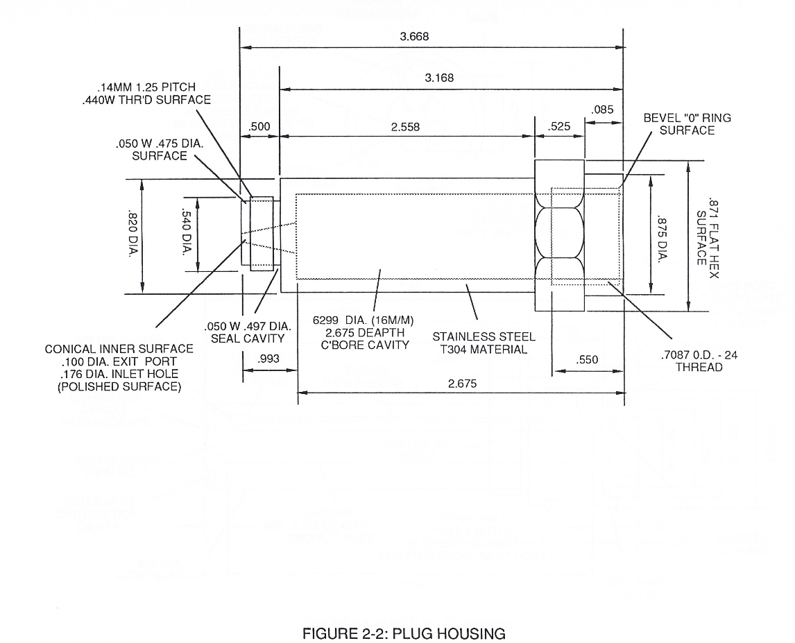
#### 2-2 Plug Housing
[](https://stanslegacy.com/uploads/images/gallery/2024-03/yfbI5Bad2TO1E8PV-image-1711246853713-20-50.png)
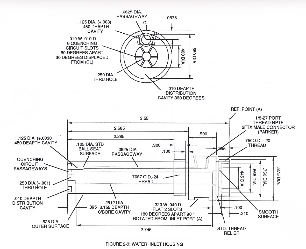
#### 2-3 Water Inlet Housing
[](https://stanslegacy.com/uploads/images/gallery/2024-03/KMImacRSwZWGL0v0-image-1711246915241-21-53.png)
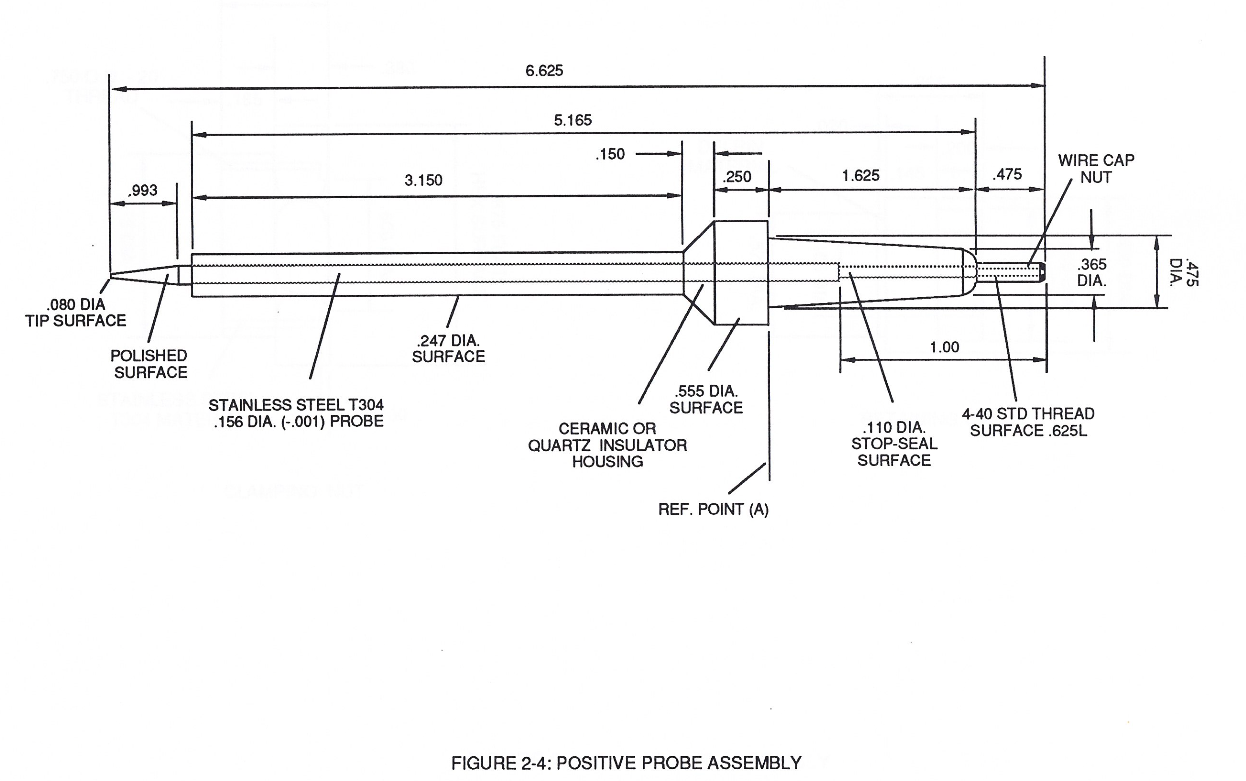
#### 2-4 Positive Probe Assembly
[](https://stanslegacy.com/uploads/images/gallery/2024-03/TSQ0VL7LmtAyqw7i-image-1711246938256-22-16.png)
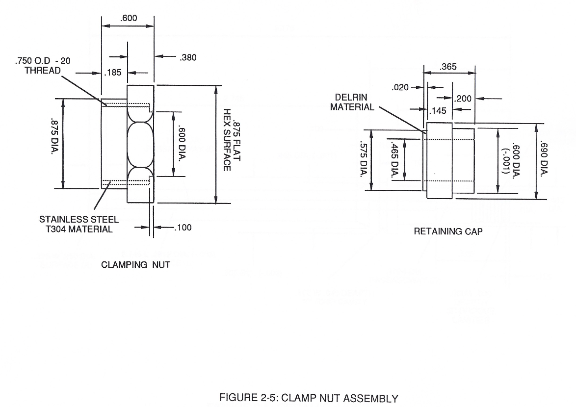
#### 2-5 Clamp Nut Assembly
[](https://stanslegacy.com/uploads/images/gallery/2024-03/5Q2M4oJgyroDNRmW-image-1711246967086-22-45.png)
#### 2-6 Ceramic Insert
[](https://stanslegacy.com/uploads/images/gallery/2024-03/HGE43QmQiGsrrURk-screenshot-2024-03-23-at-22-23-31.png)
# Steam Resonator Assembly
[](https://stanslegacy.com/uploads/images/gallery/2024-03/lJVH6rF9pwIQlyOt-image-1711426907627.jpg)
#### Steam Resonator Ass'y
[](https://stanslegacy.com/uploads/images/gallery/2024-03/IL7AVzAH9xy7GiPe-image-1711426926792.jpg)
#### S/R Mount Base
[](https://stanslegacy.com/uploads/images/gallery/2024-03/xdlIO5aopMIXsYQI-image-1711426951544.jpg)
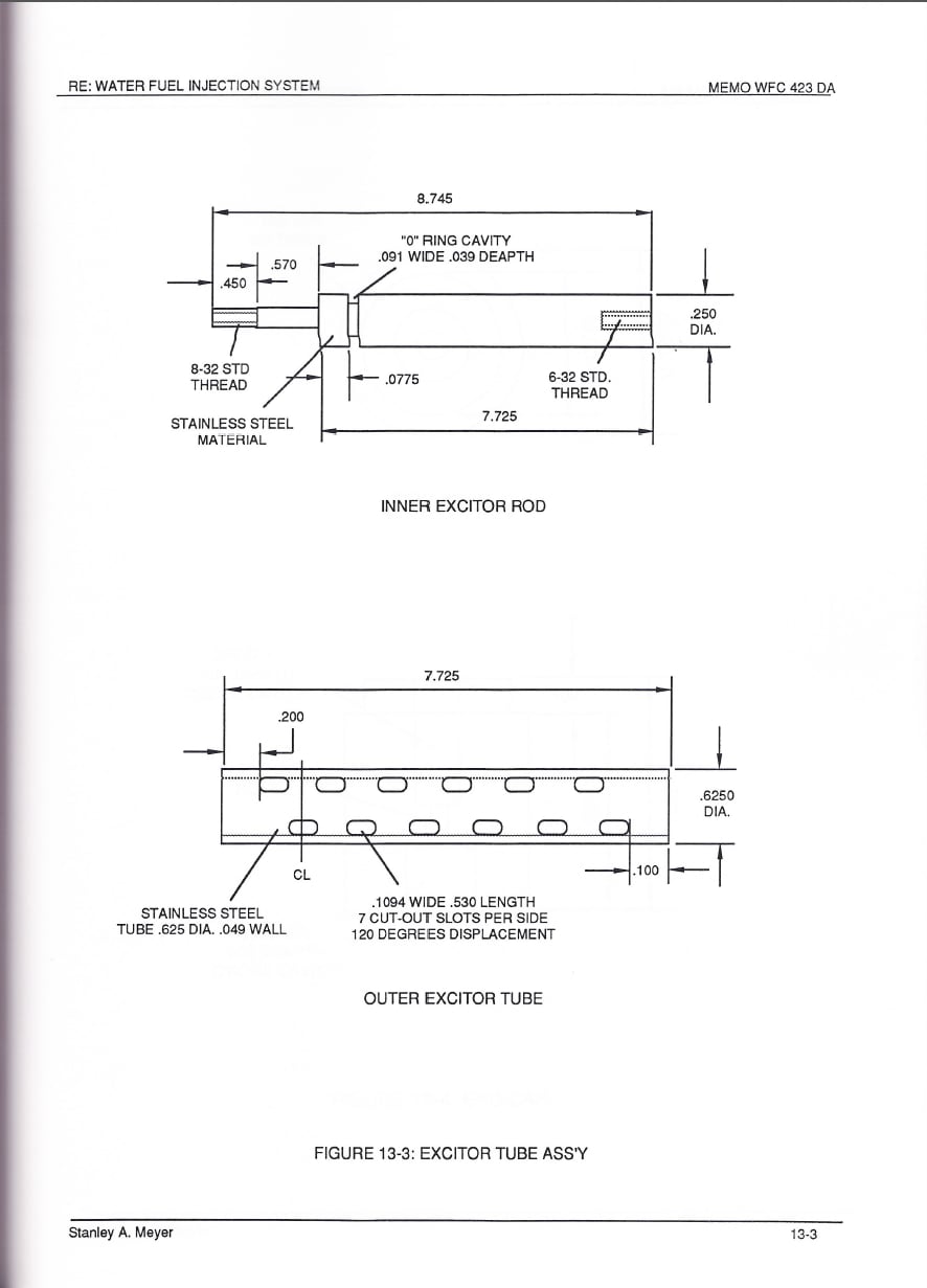
#### Excitor Tube Ass'y
#### 
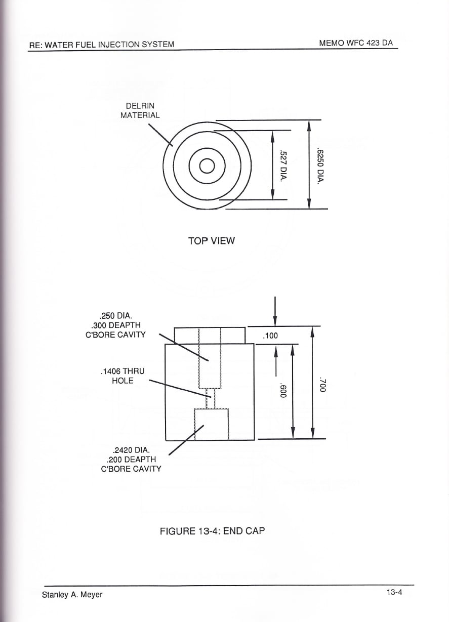
#### End Cap
[](https://stanslegacy.com/uploads/images/gallery/2024-03/MFSMfw3yQHFDLYPm-image-1711427012545.jpg)
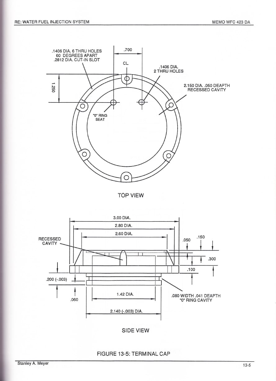
#### Terminal Cap
[](https://stanslegacy.com/uploads/images/gallery/2024-03/BwHzfNPH89vPNeMX-image-1711427031451.jpg)
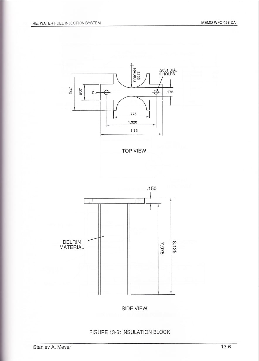
#### Insulation Block
[](https://stanslegacy.com/uploads/images/gallery/2024-03/D9NesBHaKBpN1nUo-image-1711427054347.jpg)
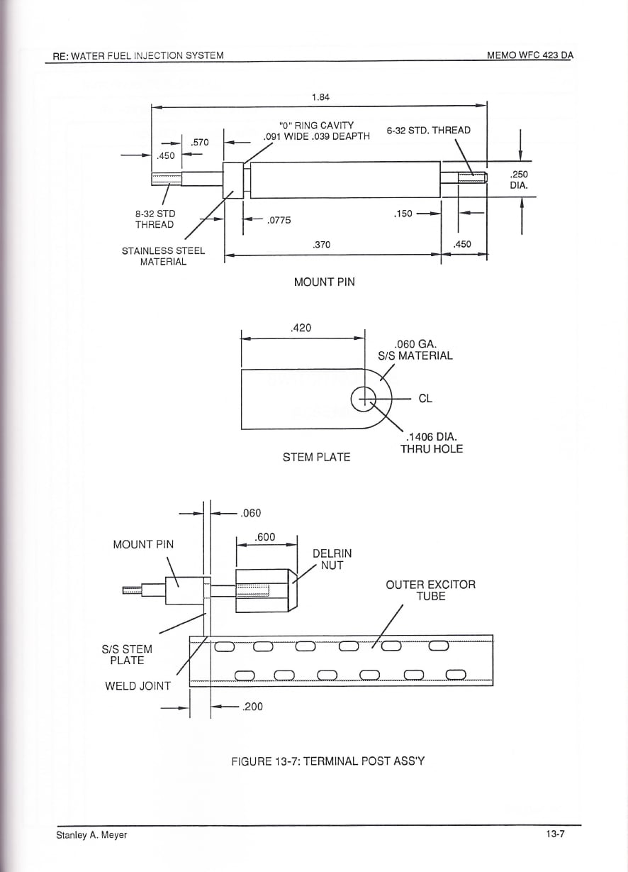
#### Terminal Post Ass'y
[](https://stanslegacy.com/uploads/images/gallery/2024-03/8YJ8M9ae1xoRasQd-image-1711427078653.jpg)
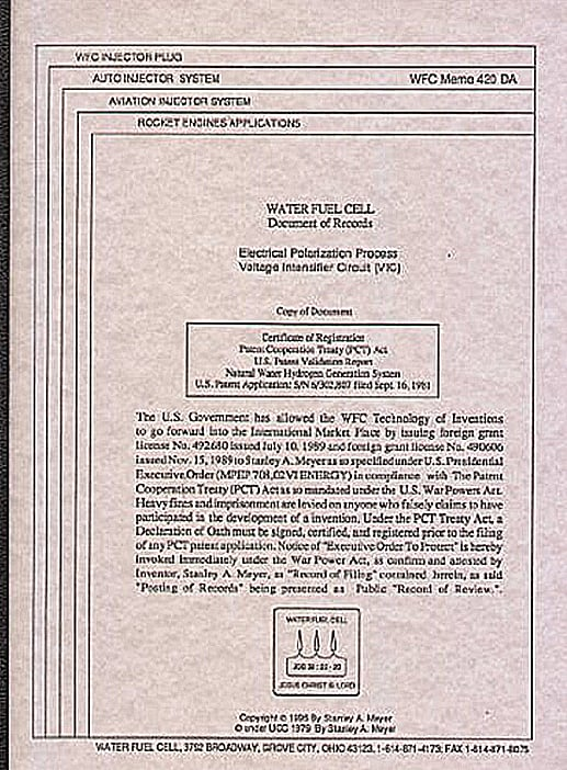
# Cover Page
[](https://stanslegacy.com/uploads/images/gallery/2024-10/JjzXNE6QP2o1kuia-image-1729734217432.png)