WFC 425 - Taper Resonant Cavity
- Water Fuel Injector
- Taper Water Fuel Injectors
- Voltage Intensifier Coil-Assembly
- Tri - Coil Construction
- WFC 425 - Illustrations
Water Fuel Injector
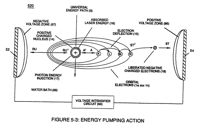
Voltage potential of opposite electrical polarity (ST - ST' - RU - RU') of Figure (5-1) (Memo WFC 424) titled "Atomic Energy Balance of Water" is further enhanced by simply electrically interfacing voltage intensifier (VIC) circuit coil-assembly (580) of Figure (6-1) with 'Taper Resonant Cavity" (590) of Figure (6-2), as schematically illustrated in (60) of Figure (3-22) as to pulse core configuration (190) of Figure (3-23) (Memo WFC 422 DA) titled "WFC Hydrogen Gas Management System.
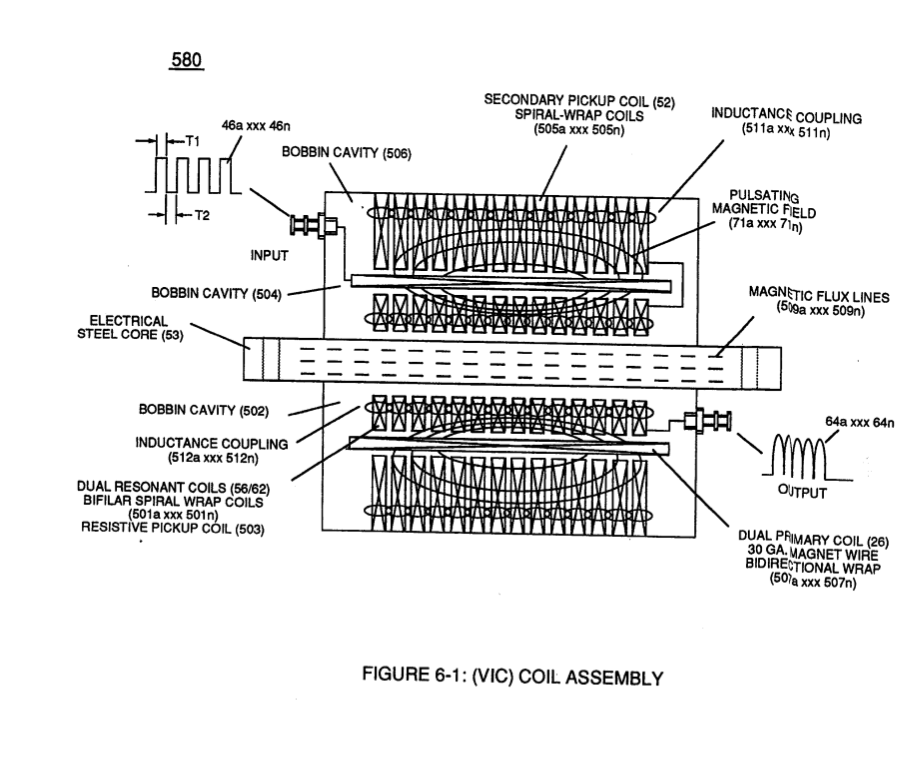
As incoming gated pulse-train (46a xxx 46n) of Figure (3-17) is electronically "tuned" to adjust pulse off- time (T2) to compensate for "rise" and "fall" of magnetic field coupling (71a xxx 71n) for a predetermined resonant pulse-frequency established and determined by the dielectric value of natural water in direct relationship to resonant cavity geometrical configuration
... dielectric value of water being 78.54 since water molecule (85) oxygen atom "L" orbit (76) occupies the maximum allowance eight electrons (79a xxx 79n), calibrated gated unipolar pulse train (64a xxx 64n) of Figure (3-20) is outputted from resonant choke (56) and electrically transmitted to positive outer conical surface (E9);
while, at the same time, negative potential of electrical intensity of force (67) (negative voltage potential) is electrically directed to inner conical surface (E1O), forming an "open-air" conical cavity (570) having parallel sides (in other cases non-linear voltage-surfaces) in space relationship (typically .010 gap) with diminishing circumference-area (E9a xxx E9n) / E10a xxx E10n) in linear progression.
Together, parallel sides (E9 / El0) not only functions as a "voltage wave-guide" (570) but, also, acts and performs as a "voltage intensifier circuit" when applied gated pulse-frequency (64a xxx 64n) travels the length of conical cavity (570) toward exit port (32).
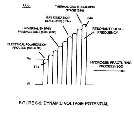
At each progressive point of diminishing circumference surface-area (E9a - b - c - d - E9n) voltage amplitude intensity increases (Vna - b - c - d - Vnn) uniformly, as illustrated in (600) of Figure (6-3) as to Travelling Voltage Wave-forms (730a - b - c) of Figure (7-12), see WFC Memo (426).
Activation point (E9a) exposes water flow (85) to voltage wave-form (64) of Figure (6-1) to begin water-to-energy conversion process (100);
at activation point (E9b) voltage intensity is increased sufficiently to perform Electrical Polarization Process (160) of Figure (3-26);
onward toward activation point (E9c) and beyond universal energy priming stage (500) of Figure (5- 1) occurs;
once activation point (E9c) is reached Gas Ionization Process (230) of Figure (3-30) takes place;
and finally, activation point (E9d) thermally ignites (atomic agitation) the "Energy-Primed" combustible gas-mixture (520) of Figure (5-3) as to (100) of Figure (4-8) by "electrostatic discharge" while being subjected to ever increasing "electrostatic pressure".
All activation points (E9a - b - c - d) performing their respective functions in sequential order in an instant of time since applied voltage level of intensity (typically 20,000 input volts or so) can be extended or increased up to and beyond 90,000 volts range within a millisecond or less.
Taper Water Fuel Injectors
Voltage wave-guide (570) allows the activation points (E9a xxx E9n) to transpire since wave-guide (570), now, functions as a Quenching Circuit (370) of Figure (3-40) to prevent gas ignition until the traveling gases (under static pressure) are exited out of and away from exit port (32) of Figure (6- 2)
... producing thermal explosive energy-yield (16), as further illustrated in (70) of Figure (4-5) titled "Voltage Triggering".
Basically, then, activation process (590), now, design - forms Water Fuel Injector (20) of Figure (4-2) as to (30) of Figure (4-11) (Memo WFC 423 DA)
... allowing Water Fuel Injectors (20a xxx 20n) to replace standard Internal Combustion Engine spark-plugs and fossil-fuel injector ports, as graphically illustrated in Figure (140) of Figure (4-12) titled "Furnace Retrofit," (150) of Figure (4-13) titled "Jet Engine retrofit," and (160) of Figure (4-14) titled "Rocket Engines Retrofit."
Voltage Intensifier Coil-Assembly
Activation Process (590) of Figure (6-2) as to (100) of Figure (4-8) is achieved since amp flow is restricted to enter into Voltage Triggering Process (70) of Figure (4-5) by way of voltage intensifier coil-assembly (580) of Figure (6-1).
|
Activation Process (590) of Figure (6-2)
|
(100) of Figure (4-8)
|
|
Voltage Triggering Process (70) of Figure (4-5)
|
voltage intensifier coil-assembly (580) of Figure (6-1)
|
Inherently, the design parameters of coil-structures (580) of Figure (6-1) determines "Efficiency" (minimizing amp leakage) by which "Voltage Intensity of Opposite Potential" (600) of Figure (6-3) can perform work to trigger Hydrogen Fracturing Process (520) of Figure (5-3) (Memo WFC 424 DA) as to (100) of Figure (4-8) (Memo WFC 423DA), as graphically denoted in (750) of Figure (7-14) of WFC memo (426) titled VIC Matrix Circuit - Instant Explosion of Water.
|
coil-structures (580) of Figure (6-1)
|
"Voltage Intensity of Opposite Potential" (600) of Figure (6-3)
|
|
Hydrogen Fracturing Process (520) of Figure (5-3)
|
(100) of Figure (4-8)
|
Tri - Coil Construction
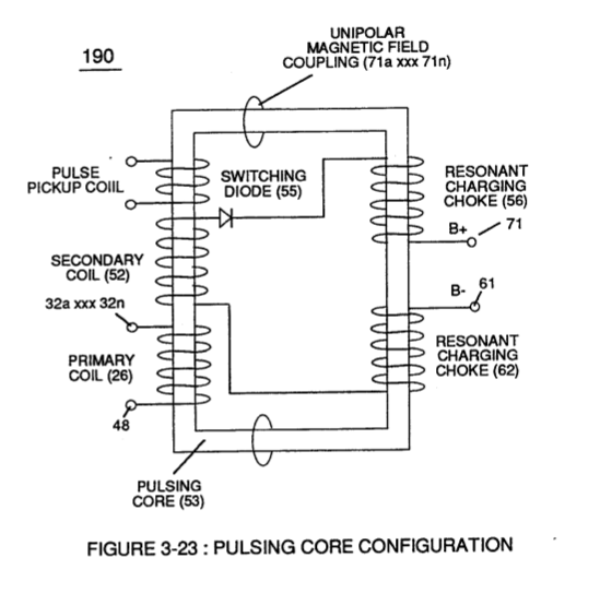 Resonant Choke Coils (56/62) of Figure (3-23) (Memo WFC 422 DA) are composed of 430F or 430FR inductance stainless steel film coated (hi dielectric value) wire (typically .004 Ga. or smaller) which are axially (spiralled) Bifilar wound about core bobbin (502), forming individual spiral-wrap (inner to outer circumference and being equally-length) coils (501a xxx 501n) electrically connected in sequential order to form resistive pickup coil (503).
Primary Coil (26) (typically .030 Ga.) film coated magnet wire is longitudinal wrapped in space relationship on top of and layered bidirectional (507a xxx 507n) across spiral-wrap coils (501a xxx 50 In) to complete bobbin cavity (504).
Secondary pickup coil (52) of Figure (3-23) is, also, composed of individual spiral wrapped coils (505a xxx 505n) (typically .002 Ga. magnet wire) electrically connected in sequential order to form bobbin cavity (506) which is placed on top of and in space relationship to primary coil cavity (504).
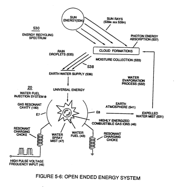
Resonant bobbin assembly (503), primary bobbin assembly (504), and secondary bobbin assembly (506), now, make up and structurally forms voltage intensifier (VIC) coil-assembly (530) of Figure (5-6) when electrical steel core material (53) forms a close-loop magnetic induction pathway centrally through and around (VIC) coil-assembly (530), as schematically illustrated in (190) of Figure (3-23) (Memo WFC 422 DA).
|
(VIC) coil-assembly (530) of Figure (5-6)
|
(190) of Figure (3-23)
|
WFC 425 - Illustrations
|
|
|
|
|
|