Manufacturing the Magnetized Gas required the development and process of taking inert gas atoms and forming a "Stable" Gas-Lattice by way of voltage stimulation called **"The Gas Bonding Process."**
The **"Newly" structured and formed Gas-Lattice** is exposed to **Laser Energy**, which is pulsed to produce a **Magnetic Pulse-Wave** that traverses pickup windings to generate electricity.The **Gas Bonding Process** is systematically activated and performed in the following way.
# RE: Electrical Particle Generator **Data Reference:** WFC Tech-Brief **Method:** How to manufacture, stimulate, and use magnetized gas to produce electrical energy on demand. **[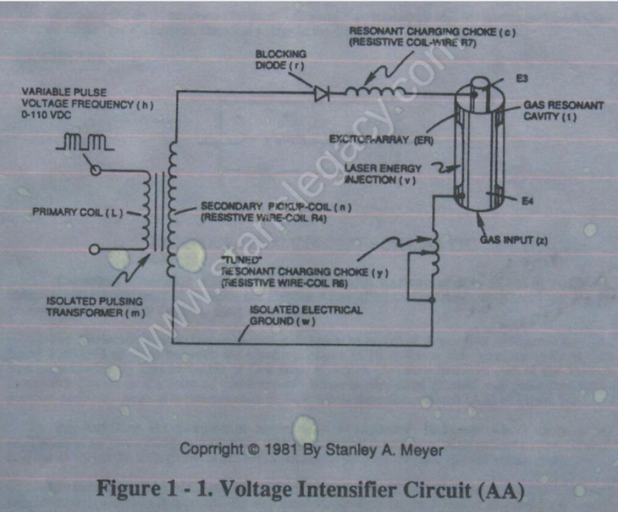](https://stanslegacy.com/uploads/images/gallery/2024-10/KHbfbIn48c46IpBu-image-1729909060083.png)Operational Parameters** - **Primary Coil (L)** - **Variable Pulse Voltage Frequency (h)** D-110 VDC - **Isolated Pulsing Transformer (m)** - **Blocking Diode (f)** - **Resonant Charging Choke (c)** (Resistive Coil-Wire R7) - **Excitor-Array (ER)** - **Secondary Pickup-Coil (n)** (Resistive Wire-Coil R4) - **"Tuned" Resonant Charging Choke (y)** (Resistive Wire-Coil R6) - **Isolated Electrical Ground (w)** - **Laser Energy Injection (v)** - **Gas Resonant Cavity (t)** - **Gas Input (z)** # CIRCUIT COMPONENT INTERACTION ##### **PULSING TRANSFORMER** The **pulsing transformer** (m) steps up voltage amplitude or voltage potential during pulsing operations. The primary coil is electrically isolated (*no electrical connection between primary and secondary coil*) to form **Voltage Intensifier Circuit** (AA).Voltage amplitude or voltage potential is increased when **secondary coil** (n) is wrapped with more turns of wire.
**Isolated electrical ground** (w) prevents electron flow from input circuit ground. ##### **BLOCKING DIODE** **Blocking Diode** (f) prevents electrical “shorting” to **secondary coil** (n) during pulse-off time since the diode “only” conducts electrical energy in the direction of the schematic arrow. --- **LC CIRCUIT** [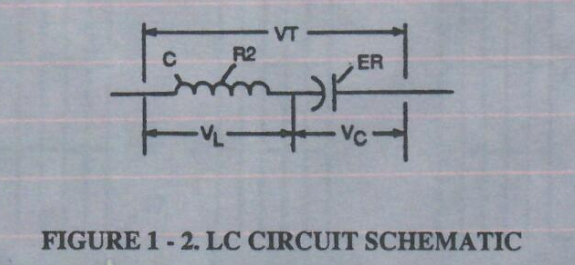](https://stanslegacy.com/uploads/images/gallery/2024-10/bz2ed0WefL8PK2ax-image-1729909194850.png)**Figure 1-2. LC Circuit Schematic****Resonant Charging Choke** (c) in series with **Excitor-array** (E3/E4) forms an **inductor-capacitor circuit** (LC) since the **Excitor-Array** (ER) of **Gas Resonant Cavity** (t) acts or performs as a capacitor during pulsing operations.
[](https://stanslegacy.com/uploads/images/gallery/2024-10/KHbfbIn48c46IpBu-image-1729909060083.png)The **Dielectric Properties** (*insulator to the flow of amps*) of **Argon Gas** (*dielectric constant being 1.000545 @ 23°C*) between the **electrical plates** (E3/E4) forms the **capacitor** (ER) of **Gas Resonant Cavity** (t). Gas Molecule or Gas atom of **Argon** (Ar) now becomes part of the Voltage Intensifier Circuit in the form of “resistance” between electrical ground and pulse-frequency positive-potential... helping to prevent electron flow within the **pulsing circuit** (AA) of Figure 1-1. The **Inductor** (c) takes on-or becomes a **Modulator Inductor** which steps up an oscillation of an given charging frequency when the effective capacitance of an pulse-forming network in order to charge the **voltage zones** (E3/E4) to an higher potential beyond applied voltage input. The **Inductance** (c) and **Capacitance** (ER of t) properties of the LC circuit is therefore “tuned” to resonate at a certain frequency.The Resonant frequency can be raised or lowered by changing the inductance and/or the capacitance values.
The established resonant frequency is, of course, independent of voltage amplitude, as illustrated in Figure 9BB.The value of the **Inductor** (c), the value of the **capacitor** (ER of t), and the pulse-frequency of the voltage being applied across the LC circuit determines the impedance of the LC circuit.
# Figure 9B & 9BB - Applied Voltage To Plates| [](https://stanslegacy.com/uploads/images/gallery/2024-10/jnFTXU8GBiPIjwpf-image-1729955474738.png) | [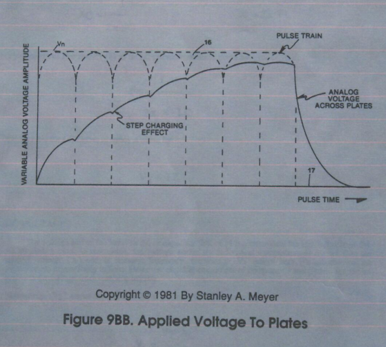](https://stanslegacy.com/uploads/images/gallery/2024-10/AYv8oCemmsC886cv-image-1729968940702.png) |
"Figure 9B. Variable Amplitude unipolar-pulse voltage frequency superimposed onto a 50% duty-cycle pulse-train."
# LC VOLTAGEThe impedance of an inductor and a capacitor in series, **Zseries**, is given by
[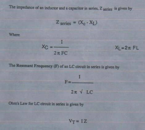](https://stanslegacy.com/uploads/images/gallery/2024-10/e2oPL6lIsE05xsc8-image-1729955826232.png) > Zseries = (Xc−Xl) Where > Xc = 1 / 2(pi)FC The **Resonant Frequency (F)** of an LC circuit in series is given by [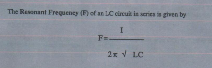](https://stanslegacy.com/uploads/images/gallery/2024-10/JBb9dYTJNfm7zqbn-image-1729955988059.png) **Ohm’s Law** for an LC circuit in series is given by > Vt = IZ ### LC VOLTAGE [](https://stanslegacy.com/uploads/images/gallery/2024-10/bz2ed0WefL8PK2ax-image-1729909194850.png)The voltage across the **inductor** (c) or **capacitor** (*ER of t*) is greater than the **applied voltage** (h).At frequency close to resonance, the voltage across the individual components is higher than the **applied voltage** (h), and, at resonant frequency, the voltage VT across both the inductor and the capacitor are theoretically infinite.
However, physical constraints of components and circuit interaction prevent the voltage from reaching infinity.
The **voltage** (VL) across the **inductor** (C) is given by the equation: # RLC CIRCUIT The **voltage** (VC) across the capacitor is given by: [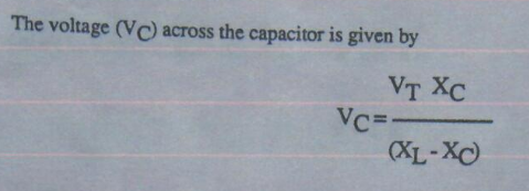](https://stanslegacy.com/uploads/images/gallery/2024-10/cO76K1Io59yaGKdl-image-1729956608556.png) During resonant interaction, the incoming **unipolar pulse-train** (h) of Figure (1-1) as to Figure (9B) produces an step-charging voltage-effect across **Excitor-Array** (ER of t), as illustrated in Figure progressive function.| Figure 1-1 | [](https://stanslegacy.com/uploads/images/gallery/2024-10/jnFTXU8GBiPIjwpf-image-1729955474738.png) Figure 9B |
Voltage intensity or level across **Excitor-Array** (*ER of t*) can exceed 20,000 volts due to **circuit** (AA) interaction and is directly related to **pulse-train** (h) variable amplitude input.
#### RLC CIRCUIT **Inductor (c)** is made of or composed of **resistive wire** (R7) to further restrict D.C. current flow beyond **inductance reaction** (XL), and is given by [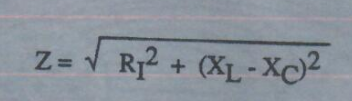](https://stanslegacy.com/uploads/images/gallery/2024-10/tMbmcRV4nVm5Pmqf-image-1729957184564.png) #### Dual-inline RLC NETWORK Variable **inductor-coil** (y), similar to **inductor** (c) connected to **opposite polarity voltage zone** (E4) further inhibits electron movement or deflection within the Voltage Intensifier Circuit.Moveable wiper arm fine “tunes” "**Resonant Action"** during pulsing operations.
**Inductor** (y) in relationship to **inductor** (c) electrically balances the opposite voltage electrical potential across voltage zones (E3/E4). #### VIC RESISTANCE Since **pickup coil** (n) is also composed of or made of **resistive wire-coil** (R4), then, total circuit resistance is given by [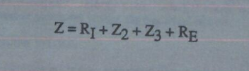](https://stanslegacy.com/uploads/images/gallery/2024-10/0VNxGIFmANBN7u7A-image-1729957065211.png) Where, RE is the dielectric constant of **Argon** (Ar). # VOLTAGE DYNAMIC**Electrical power** (P) is a linear relationship between two variables, **voltage** (E) and **Amps** (I).
#### [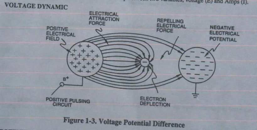](https://stanslegacy.com/uploads/images/gallery/2024-10/BBmcT02kH4T3CRqR-image-1729957262428.png)VOLTAGE DYNAMIC - **Positive Electrical Field** - **Electrical Attraction Force** - **Electron Deflection** - **Repelling Electrical Force** - **Negative Electrical Potential** - **Positive Pulsing Circuit** **Figure 1-3. Voltage Potential Difference** --- #### POTENTIAL ENERGY Voltage is “**electrical pressure**” or “**electrical force**” within an electrical circuit and is known as “**voltage potential**.” The higher the voltage potential, the greater the **force** or **electrical repelling force** is applied to the electrical circuit. Voltage potential is an **unaltered** or **unchanged** energy-state when “**electron movement**” or “**electron deflection**” is prevented or restricted within the electrical circuit. # Voltage Performs Work Unlike voltage charges within an electrical circuit set up an “electrical attraction force”; in both cases, electrical charges within the same electrical circuit generates an **repelling action**. Electrical **forces** are known as “voltage fields” and can exhibit either a positive or negative electrical charge. Likewise, Ions or Particles within the electrical circuit having unlike electrical charges are attracted to each other. Ions or particles mass having the same or like electrical charges will move away from one another, as illustrated in Figure 1-3. > Furthermore, electrical charged ions or particles can move toward stationary voltage fields of opposite polarity, and, is given by Newton's second law [](https://stanslegacy.com/uploads/images/gallery/2024-10/rfu0roxmFm5kA9nb-image-1729957507236.png) Where > The **acceleration** (A⃗) of an **particle mass** (M) acted on by a **Net Force** (F⃗). Whereby **Net Force** (F⃗) is the “electrical attraction force” between opposite electrically charged entities, and, is given by Coulomb’s Law [](https://stanslegacy.com/uploads/images/gallery/2024-10/xT4hfHOKgfLDqdzM-image-1729957567021.png) WhereasDifference of potential between two charges is measured by the work necessary to bring the charges together, and, is given by
[](https://stanslegacy.com/uploads/images/gallery/2024-10/dHbty7meydgcMmK1-image-1729957581910.png) The potential at a point due to a **charge** (q) at a **distance** (R) in a medium whose **dielectric constant** is (e). # ATOMIC INTERACTION TO VOLTAGE STIMULATION [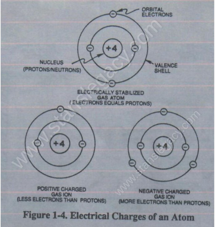](https://stanslegacy.com/uploads/images/gallery/2024-10/S5tAw3FDTz0ptGiT-image-1729957777023.png) Atomic structure of an atom exhibits two types of electrical charged mass-entities, orbital electrons having **negative electrical charges** (-) and a **Nucleus** (*at least one proton*) having a **positive electrical charge** (+). The positive electrical charge of the Nucleus equals the sum total of all negative electrical charged electrons when the Atom is in “stable-state.”In **stable-state** or **normal-state**, the number of electrons equals the number of protons to give the atom “**NO**” net electrical charge.
Whenever one or more electrons are “**dislodged**” from the atom, the atom takes-on a net positive electrical charge and is called a positive ion. If an electron combines with an stable or normal atom, the atom has a net negative charge and is called a negative ion. ---Voltage potential within an electrical circuit can cause one or more electrons to be dislodged from the atom due to opposite electrical polarity attraction between unlike charged entities, as shown in Figure 1-5 (see Figure 1-3 again) as to **Newton’s** and **Coulomb’s Laws** of electrical-force.
| [](https://stanslegacy.com/uploads/images/gallery/2024-10/BBmcT02kH4T3CRqR-image-1729957262428.png) | [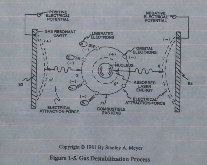](https://stanslegacy.com/uploads/images/gallery/2024-10/dmamtcwtGzMDRJnB-image-1729960689754.png) |
The illustrated **Argon Atom** becomes electrical charged ion when the electron number changes from 18, as illustrated in Figure 1-4.
# Gas Destabilization Process [](https://stanslegacy.com/uploads/images/gallery/2024-10/dmamtcwtGzMDRJnB-image-1729960689754.png)Placement of a pulse-voltage potential across the **Excitor-Array** (ER) of **Gas Resonant Cavity** (t) while inhibiting or preventing electron flow within the **Voltage Intensifier Circuit** (AA) causes the Gas Atom of **Argon** (Ar) to become an positive charged ion by pulling away orbital electrons from the gas molecule or gas atom, as illustrated in Figure 1-5. The stationary **"positive"** **electrical** **voltage-field** (E3) attracts the negative charged electrons from the Gas Atom. At the same time, the stationary **"Negative"** **electrical voltage field** (E4) attracts the positive charged nucleus of the **gas atom** (s).Once the negative electrically charged electrons are dislodged from the gas atom, the gas atom becomes destabilized…having missing electrons.
Dislodging electrons from the gas atom by way of voltage stimulation is hereinafter called **"The Gas Destabilization Process."**Attenuating and adjusting the **"pulse-voltage-amplitude"** with respect to the **"pulse voltage frequency,"** now, regulates **"The Electron Extraction Process."**
# LASER INTERACTION **Laser energy** (v) of Figure 1-1 is now injected into or superimposed onto the **Gas Destabilization Process** to help promote the **Electron Extraction Process** *since the absorbed light energy (electromagnetic energy*) forces the gas atom electrons to an higher energy state or **attraction-force** (q2) between the orbital electrons and the nucleus… weakening the **electrical attraction-force** (qq') between the orbital electrons and the nucleus, as illustrated in Figure 1-5 as to Figure 20JX.| [](https://stanslegacy.com/uploads/images/gallery/2024-10/dmamtcwtGzMDRJnB-image-1729960689754.png) | [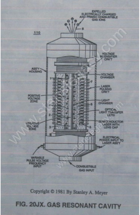](https://stanslegacy.com/uploads/images/gallery/2024-10/8c29PMYgLRdtaSmR-image-1729961324526.png) |
Le is light intensity in watts; T1 is current on-time; T2 is current off-time; and (ION) = RMS value of load current during on-period.
By varying or regulating laser intensity in direct relationship to applied pulse-voltage frequency and voltage amplitude causes the inert gas atom of **Argon** (Ar) to become a positive charged gas ion having missing electrons.
The **Gas Destabilization Process** with **Laser Injection** is, also, applicable to other types of airborne or free-floating atoms.
--- [](https://stanslegacy.com/uploads/images/gallery/2024-10/IVsmnYjO91b2mWUJ-image-1729961570293.png) **Electron Extraction Circuit** (BB) of Figure 1-7 removes, captures, and consumes the "dislodged" electrons (*from the gas atoms*) to cause the gas atoms to go into and reach "ion-state," forming highly energized gas atoms having missing electrons.**Resistive values** (R4, R6, R7, and **dielectric constant of gas** Rg) and **isolated electrical ground** (W) prevents "electron-flow" or "electron deflection" from occurring within **circuit** (BB) during pulsing operations (*at resonant frequency*) and, therefore, keeps the gas atoms in ion state by **"NOT"** allowing electron replacement to occur or take place between the moving gas atoms.
[](https://stanslegacy.com/uploads/images/gallery/2024-10/dmamtcwtGzMDRJnB-image-1729960689754.png)The "dislodged" negative charged electrons are "destroyed" or "consumed" in the form of "heat" when **Amp Consuming Device** (S) (*such as a light bulb*) is positive electrically energized during alternate pulsing operations. Laser activated or laser primed gas ions repels the "dislodged" electrons being consumed, as illustrated in Figure 1-5.The **Electron Extraction Process** (BB) is, hereinafter, called **"The GAS RESONANT CAVITY,"** as illustrated in Figure 1-7 as to Figure 20JX.
| [](https://stanslegacy.com/uploads/images/gallery/2024-10/IVsmnYjO91b2mWUJ-image-1729961570293.png) | [](https://stanslegacy.com/uploads/images/gallery/2024-10/8c29PMYgLRdtaSmR-image-1729961324526.png) |
Covalent bonding between like atoms does not occur due to the “stronger” **Electrical Attraction-Force** (qq') between the unlike atoms.
During Gas-Lattice formation, **Iron ions** (Fe+) can be replaced by other atoms exhibiting magnetic properties such as **Nickel ions** (Ni+) or **Cobalt ions** (Co+).
**Gas-Lattice formation** of unlike atoms by way of the **Electron Extraction Process** is, hereinafter, called **"The Gas Bonding Process"**.
# Electromagnetic Enhancement The newly **"structured"** Gas-Lattice becomes magnetized when, momentarily, exposed to a magnetic field, as illustrated in Figure 1-9. Since the electrons of the **Iron ion** (Fe+) spin in one direction only (*SEE FIGURE 1-10*) (*Nickel ions and Cobalt ions in like manner*), the magnetic field of each Iron ion (*called Domains*) unite and form a "Discrete" magnetic field called an **"Magnetic Flux-Line"**.| [](https://stanslegacy.com/uploads/images/gallery/2024-10/oXF2FKsD6nLxZRtN-image-1729968565897.png) | [](https://stanslegacy.com/uploads/images/gallery/2024-10/ZAeR0gjRwhmhQlRO-image-1729968529604.png) |
Grouping the **Magnetic Flux-Lines** together forms an **"Stable"** magnetic field since the magnetic coupling-field between the Iron ions or Domains help to hold the Iron ions in an linear alignment beyond the bonding strength of the **Gas-Lattice**.
Magnetic Field Strength is **"measured"** in GAUSS UNITS and is determined by the linear volume of the Gas-Lattice.
# Magnetic Field Enhancement **[](https://stanslegacy.com/uploads/images/gallery/2024-10/5lkF2do24wqUm7pz-image-1729968719689.png)Magnetic Field Enhancement** occurs when the **Magnetized Gas-Lattice** (placed inside EPG close-loop tubular system) is exposed to and interacts with **Laser energy**, as illustrated in Figure 29 WFC Tech-brief. The absorbed Laser energy forces the Iron ions' **ELECTRONS** to spin at a faster rate when taken to a higher energy level, which, in turn, amplifies and strengthens the magnetic field (*Domain magnetic field*) of the Iron ions.The spinning electrons simply interact with both electrostatic forces and electromagnetic forces to produce an enhanced magnetic field.
> This magnetic process is an extension of **"The Electron Theory Of Magnetism"**.Increasing Laser intensity increases the magnetic field strength of the gas-lattice in a linear function. **NICKEL IONS** and **COBALT IONS** are interchangeable with and duplicate the magnetic properties of Iron ions undergoing Laser priming.
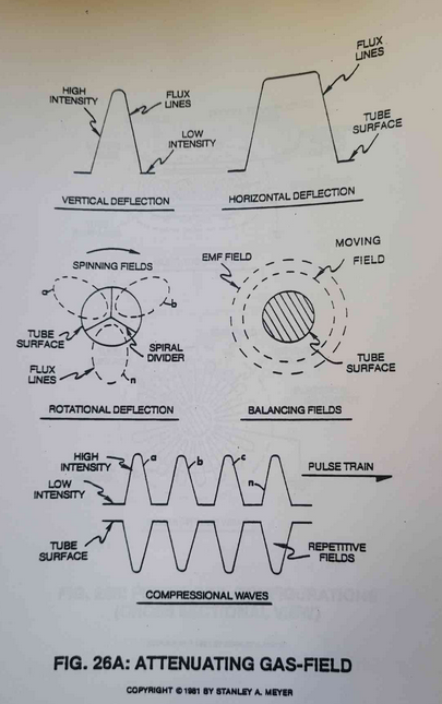
[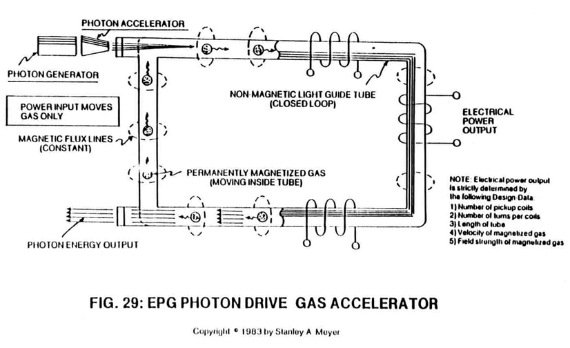](https://stanslegacy.com/uploads/images/gallery/2024-10/MfYuwau4z4tLpfGE-image-1729568854073.png)In **Quiescent-State**, the laser energy is superimposed onto the **Gas-Lattice** and "stored" inside the close-loop tubular EPG system to maintain a given or predetermined magnetic field strength during EPG operations.In **Active-State**, the laser energy is pulsed and passes through the **Gas-Lattice** to produce a magnetic pulse-wave, as illustrated in Figure 29 as to Figure 26A and 26B.
| [](https://stanslegacy.com/uploads/images/gallery/2024-10/D4Qg7p3ENqyP0N8k-image-1729730005256.png) | [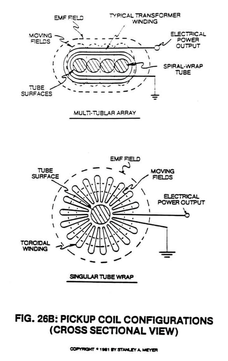](https://stanslegacy.com/uploads/images/gallery/2024-10/rYPtRRwOcSG20Hyf-image-1729730524941.png) |
In either case, the resultant magnetic field transverses pickup-coils to produce electrical energy.
# WFC 420 - Hydrogen Fracturing Process # Hydrogen Fracturing Process ### ... using Water as Fuel. Over the Years man has used water in many ways to make his life on Earth more productive. Why not,now, use water as fuel to power our cars, heat our homes, fly our planes or propel spaceships beyond our galaxy?Biblical prophesy foretells this event.
After all, the energy contained in a gallon of water exceeds 2.5 million barrels of oil when equated in terms of atomic energy.Water, of course, is free, abundant, and energy recyclable.
The Hydrogen Fracturing Process dissociates the water molecule by way of voltage stimulation, ionizes the combustible gases by electron ejection and, *then*, prevents the formation of the water molecule during thermal gas ignition
... releasing thermal explosive energy beyond "normal" gas burning levels under control state ... and the atomic energy process is environmentally safe. The Hydrogen Fracturing Process is systematically activated and performed in the following way: #### Hydrogen Fracturing Process Method Using "**Voltage Potential**" to stimulate the water molecule to produce atomic energy on demand. ##### ##### Operational Parameters: # Pulsing Transformer The **pulsing transformer** (A/G) steps up the voltage amplitude or voltage potential during pulsing operations. The primary coil is electrically isolated (no electrical connection between primary and secondary coil) to form **Voltage Intensifier Circuit** (AA) Figure (1-1). [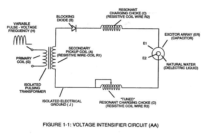](https://stanslegacy.com/uploads/images/gallery/2023-12/qhtqz9LzDjg4722f-image-1703011664617.png) Voltage amplitude or voltage potential is increased when **secondary coil** (A) is wrapped with more turns of wire. **Isolated electrical ground** (J) prevents electron flow from input circuit ground. # Blocking Diode **Blocking Diode** (B) prevents electrical "shorting" to secondary coil (A) during pulse-off time since the diode "**only**" conducts electrical energy in the direction of the schematic arrow. [](https://stanslegacy.com/uploads/images/gallery/2023-12/qhtqz9LzDjg4722f-image-1703011664617.png) # LC Circuit **Resonant Charging Choke** (C) in series with **Excitor-array** (E1/E2) forms an **inductor-capacitor circuit** (LC) since the **Excitor-Array** (ER) acts or performs as an capacitor during pulsing operations, as illustrated in Figure (1-2) as to Figure (1-1).| Figure (1-2) [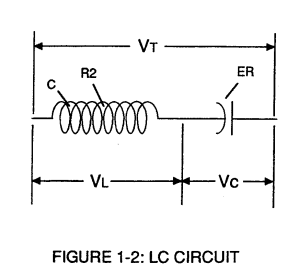](https://stanslegacy.com/uploads/images/gallery/2023-12/VzsK8hdVflGHQSyd-image-1703011673363.png) | Figure (1-1) [](https://stanslegacy.com/uploads/images/gallery/2023-12/qhtqz9LzDjg4722f-image-1703011664617.png) |
... helping to prevent electron flow within the **pulsing circuit** (AA) of Figure 1-1.
[](https://stanslegacy.com/uploads/images/gallery/2023-12/qhtqz9LzDjg4722f-image-1703011664617.png) The **Inductor** (C) takes on or becomes an **Modulator Inductor** which steps up an oscillation of an given charging frequency with the effective capacitance of an pulse-forming network in order to charge the **voltage zones** (E1/E2) to an higher potential beyond applied voltage input. The **Inductance** (C) and **Capacitance** (ER) properties of the LC circuit is therefore "**tuned**" to resonance at a certain frequency.The Resonant Frequency can be raised or lowered by changing the inductance and/or the capacitance values.
The established **resonant frequency** is, of course, independent of voltage amplitude, as illustrated in Figure (1-3) as to Figure (1-4).
| Figure (1-3) [](https://stanslegacy.com/uploads/images/gallery/2023-12/KS1IdCNzwsPJRslu-image-1703011682305.png) | Figure (1-4) [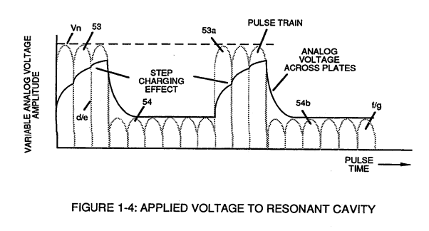](https://stanslegacy.com/uploads/images/gallery/2023-12/BVSJKDz1yh7YR7m9-image-1703011690241.png) |
The impedance of an inductor and a capacitor in series, Z series is given by (Eq 1)
[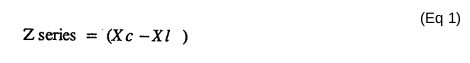](https://stanslegacy.com/uploads/images/gallery/2023-12/5kijCBV9DAnEaHJ7-image-1703012652433.png) Where: [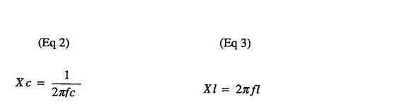](https://stanslegacy.com/uploads/images/gallery/2023-12/WGRmcuSIYoItCgHP-image-1703012669666.png)The Resonant Frequency (F) of an LC circuit in series is given by (Eq 4)
[](https://stanslegacy.com/uploads/images/gallery/2023-12/OG0MPPsrNVExMFqI-image-1703012692611.png)Ohm's Law for LC circuit in series is given by:
[](https://stanslegacy.com/uploads/images/gallery/2023-12/YlXMelnpzpt0EBZg-image-1703012708035.png) # LC Voltage The voltage across the **inductor** (C) or **capacitor** (ER) is greater than the **applied voltage** (H).At frequency close to resonance, the voltage across the individual components is higher than the applied voltage (H),
and, at **resonant frequency**, the voltage VT across both the **inductor** and the **capacitor** are *theoretically infinite*.
However, **physical constraints** of components and **circuit interaction** prevents the voltage from reaching infinity.
The voltage (VL) across the inductor (C) is given by the equation (Eq 6) [](https://stanslegacy.com/uploads/images/gallery/2023-12/CZZWea4p0NaEqwRU-image-1703012863032.png) The voltage (VC) across the capacitor is given by (Eq 7) [](https://stanslegacy.com/uploads/images/gallery/2023-12/6egjXbId58fGa3UB-image-1703012889070.png) During **resonant interaction**, the incoming unipolar **pulse-train** (H) of Figure (1-1) as to Figure (1-5) produces a **step-charging voltage-effect** across **Excitor-Array** (ER), as illustrated in Figure (1-3) and Figure (1-4).| Figure (1-1) [](https://stanslegacy.com/uploads/images/gallery/2023-12/qhtqz9LzDjg4722f-image-1703011664617.png) | Figure (1-5) [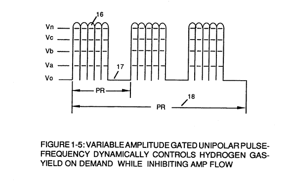](https://stanslegacy.com/uploads/images/gallery/2023-12/l7jnV5JDH3YDsfqc-image-1703011705003.png) |
| Figure (1-3) [](https://stanslegacy.com/uploads/images/gallery/2023-12/KS1IdCNzwsPJRslu-image-1703011682305.png) | Figure (1-4) [](https://stanslegacy.com/uploads/images/gallery/2023-12/BVSJKDz1yh7YR7m9-image-1703011690241.png) |
Voltage intensity increases from zero '**ground-state**' to a **high positive voltage potential** in an progressive function.
Once the voltage-pulse is terminated or **switched-off**, voltage potential returns to "**ground-state**" or near ground-state, to start the voltage deflection process over again.Voltage intensity or level across **Excitor-Array** (ER) can ***exceed 20,000 volts*** due to circuit (AA) interaction and is directly related to **pulse-train** (H) variable amplitude input.
# RLC Circuit **Inductor** (C) is made of or composed of **resistive wire** (R2) to further restrict D.C. current flow beyond inductance reaction (XL), and, is given by [](https://stanslegacy.com/uploads/images/gallery/2023-12/wtUVCbgdpbLH0jj5-image-1703010769680.png) # Dual-inline RLC Network **Variable inductor-coil** (D), similar to **inductor** (C) connected to **opposite polarity voltage zone** (E2) further inhibits electron movement or **deflection** within the **Voltage Intensifier Circuit**.**Movable wiper** arm fine "tunes" "**Resonant Action**" during pulsing operations.
**Inductor** (D) in relationship to **inductor** (C) electrically balances the **opposite voltage electrical potential** across **voltage zones** (E1/E2).
[](https://stanslegacy.com/uploads/images/gallery/2023-12/qhtqz9LzDjg4722f-image-1703011664617.png) # VIC Resistance Since **pickup coil** (A) is also composed of or made of **resistive wire-coil** (Rl), then, total circuit resistance is given by (Eq 9) [](https://stanslegacy.com/uploads/images/gallery/2023-12/VTFgSLZMPltjzDDx-image-1703014018717.png) Where, RE is the dielectric constant of natural water. Ohm's Law as to applied electrical power, which is (Eq 10) [](https://stanslegacy.com/uploads/images/gallery/2023-12/yREAXl76dv0m53pn-image-1703014036991.png) Where, (Eq 11) [](https://stanslegacy.com/uploads/images/gallery/2023-12/nFBfPhXRmPu5u8SH-image-1703014044957.png)Whereby**, Electrical power** (P) is an linear relationship between two variables, **voltage** (E) and **amps** (I).
# Potential Energy #### Voltage Dynamic Voltage is "**electrical pressure**" or "**electrical force**" within an electrical circuit and is known as "**voltage potential**". The higher the **voltage potential**, the greater "**electrical attraction force**" or "**electrical repelling force**" is applied to the electrical circuit.Voltage potential is an "**unaltered**" or “**unchanged**" energy-state when "**electron movement**" or "**electron deflection**" is prevented or restricted within the electrical circuit.
# Voltage Performs Work Unlike voltage charges within an electrical circuit sets up an "**electrical attraction force**; whereas, like electrical charges within the same electrical circuit encourages an "**repelling action**".In both cases, electrical charge deflection or **movement** is directly related to applied voltage.
These electrical "**forces**" are known as "**voltage fields**" and can exhibit either a **positive** or **negative** electrical charge. Likewise, **Ions** or **particles** within the electrical circuit having unlike electrical charges are attracted to each other. **Ions** or **particle masses** having the same or like electrical charges will move away from one another, as illustrated in Figure (1-6).Furthermore, electrical charged ions or particles can move toward **stationary voltage fields** of opposite polarity, and, is given by Newton's second Law (Eq 12)
[](https://stanslegacy.com/uploads/images/gallery/2023-12/A8KMoSTkoLOevgOw-image-1703014342118.png) WhereThe **acceleration** (A) of an **particle mass** (M) acted on by a **Net Force** (F).
Whereby **Net Force** (F) is the "**electrical attraction force**" between opposite electrically charged entities, and, is given by **Coulomb's Law** (Eq 13) [](https://stanslegacy.com/uploads/images/gallery/2023-12/iVFgAniwEQuWhTzr-image-1703014358200.png) Whereas Difference of potential between two charges is measured by the work necessary to bring the charges together, and, is given by (Eq 14) [](https://stanslegacy.com/uploads/images/gallery/2023-12/L6Z73NT5wp8pRmJP-image-1703014374624.png) The potential at a point due to a **charge** (q) at a **distance** (R) in a medium whose **dielectric constant** is (e). # Atomic Interaction to Voltage Stimulation Atomic structure of an atom exhibits two types of electrical charged mass-entities. **Orbital electrons** having **negative electrical charges** (-) and a **nucleus** composed of **protons** having **positive electrical charges** (+). In stable electrical state, the number of negative electrically charged electrons **equals** the same number of positive electrically charged protons ... forming an atom having "no" **net electrical charge**.Whenever one or more electrons are "**dislodged**" from the atom, the atom takes on a **net positive electrical charge** and is called a **positive ion**.
If an electron **combines** with a stable or normal atom, the atom has a **net negative charge** and is called a **negative ion**.
Voltage potential within an electrical circuit (see **Voltage Intensifier Circuit** as to Figure 1-1) can cause one or more electrons to be dislodged from the atom due to opposite polarity attraction between unlike charged entities, as shown in Figure (1-8).| **Voltage Intensifier Circuit** as to Figure 1-1 [](https://stanslegacy.com/uploads/images/gallery/2023-12/qhtqz9LzDjg4722f-image-1703011664617.png) | Figure (1-8) [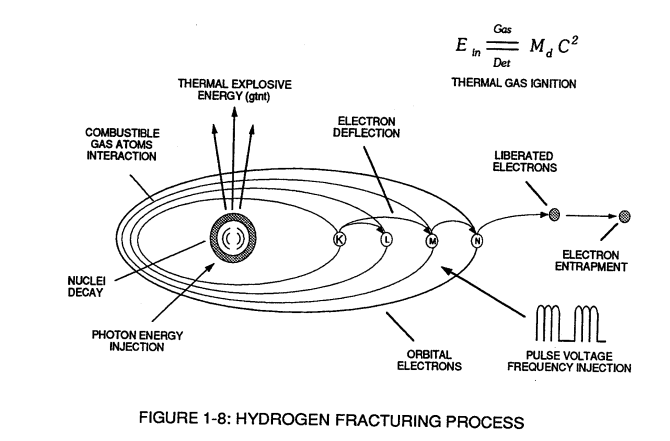](https://stanslegacy.com/uploads/images/gallery/2023-12/JwVGwSzunMi3kshP-image-1703014820006.png) |
The resultant electrical attraction force (qq') combines or joins unlike atoms together by way of **covalent bonding** to form molecules of gases, solids, or liquids.
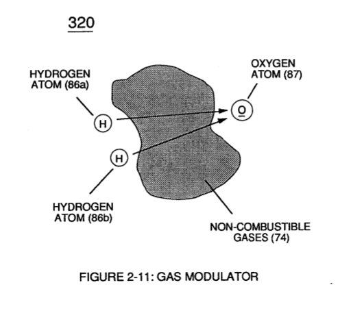
[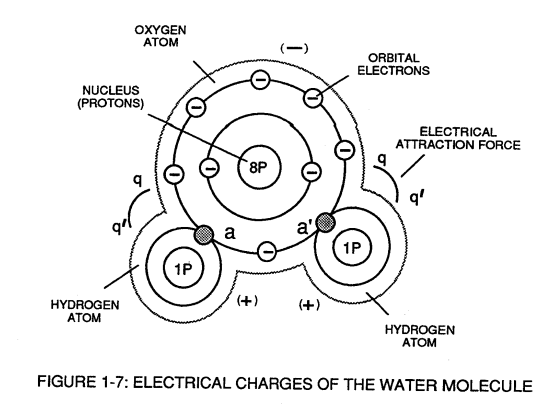](https://stanslegacy.com/uploads/images/gallery/2023-12/OPnNcyNwXCESXxxs-image-1703011752626.png)When the unlike oxygen atom combines with two hydrogen atoms to from the water molecule by accepting the hydrogen electrons (aa' of Figure 1-7), the oxygen atoms become "net" **negative electrically charged** (-) since the restructured oxygen atom now occupies 10 negative electrically charged electrons as to only 8 positive electrically charged protons. The hydrogen atom with only its **positive charged proton remaining** and **unused**, now, takes on a "net" **positive electrical charge** *equal to* the electrical intensity of the negative charges of the two **electrons** (aa') being shared by the oxygen atom. ... satisfying the law of physics that *for every action there is an equal and opposite reaction*. The sum total of the **two positive charged hydrogen atoms** (++) equaling the **negative charged oxygen atom** (--) forms a "no" net electrical charged molecule of water.Only the unlike atoms of the water molecule exhibits opposite electrical charges.
# Voltage Dissociation of The Water Molecule Placement of a **pulse-voltage potential** across the **Excitor-Array** (ER) while inhibiting or preventing electron flow from within the **Voltage Intensifier Circuit** (AA) causes the water molecule to separate into its component parts by, ***momentarily***, pulling away orbital electrons from the water molecule, as illustrated in Figure (1-9). [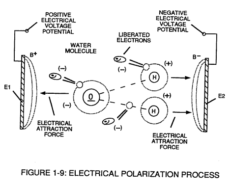](https://stanslegacy.com/uploads/images/gallery/2023-12/4XkiC7I7LVDpsfmO-image-1703011782177.png)The stationary "positive" **electrical voltage-field** (E1) not only attracts the **negative charged oxygen atom** but also **pulls away negative charged electrons** from the water molecule. At the same time, the stationary **"negative" electrical voltage field** (E2) attracts the **positive charged hydrogen atoms**.Once the negative electrically charged electrons are **dislodged** from the water molecule, **covalent bonding** (sharing electrons) ceases to exist, **switching-off** or **disrupting** the **electrical attraction force** (qq') between the water molecule atoms.
The liberated and moving atoms (*having missing electrons*) regain or capture the free floating electrons once applied voltage is switched-off during pulsing operations. The liberated and electrically stabilized atoms having a net electrical charge of "zero" exit the water bath for hydrogen gas utilization.Dissociation of the water molecule by way of voltage stimulation is herein called '**The Electrical Polarization Process**".
Subjecting or exposing the water molecule to even higher voltage levels causes the liberated atoms to go into a "state" of gas ionization.Each liberated atom taking-on its own "net" **electrical charge**.
The ionized atoms along with free floating negative charged electrons are, now, deflected (pulsing electrical voltage fields of opposite polarity) through the **Electrical Polarization Process**… imparting or superimposing a **second physical-force** (*particle-impact*) unto the electrically charged water bath.
[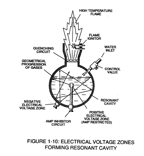](https://stanslegacy.com/uploads/images/gallery/2023-12/zsCMBBwfkWoq9neZ-image-1703011792203.png)**Oscillation** (back and forth movement) of electrically charged particles by way of voltage deflection is hereinafter called "**Resonant Action**", as illustrated in Figure (1-10).
Attenuating and adjusting the "**pulse-voltage-amplitude**" with respect to the "**pulse voltage frequency**", now, produces hydrogen gas on demand while restricting amp flow.
# Laser Interaction **[](https://stanslegacy.com/uploads/images/gallery/2023-12/QpGkWk3GM41m99vV-image-1703011803057.png)Light-emitting diodes** arranged in a **Cluster-Array** (see Figure 1-11) provides and emits a narrow band of visible light energy into the voltage stimulated water bath, as illustrated in Figure (1-13) as to Figure (1-12).| Figure (1-13) [](https://stanslegacy.com/uploads/images/gallery/2023-12/hAAtdFuWmDfeRzsr-image-1703011825328.png) | Figure (1-12) [](https://stanslegacy.com/uploads/images/gallery/2023-12/xosAehbokL7U71yH-image-1703011813778.png) |
Laser or light intensity is variable as to duty cycle on/off pulse-frequency from 1Hz to 65 Hz and above is given by (Eq 17)
[](https://stanslegacy.com/uploads/images/gallery/2023-12/NdbDeazdTkeICwVN-image-1703015902793.png)Le is light intensity in watt; T1 is current on-time; T2 is current off-time; and (ION)=RMS value of load current during on-period.Injecting **Laser Energy** into the **Electrical Polarization Process** and controlling the intensity of the light-energy causes the **Combustible Gases** to reach a **higher energy-state** (*electromagnetically priming the combustible gas ions*) which, in turn, accelerates gas production while **raising gas-flame temperatures** beyond "normal" gas-burning levels.
Injecting "**Electromagnetically Primed**" and "**Electrically Charged**" **combustible gas ions** (from water) into other light-activated **Resonant Cavities** further promotes gas-yield beyond voltage/laser stimulation, as illustrated in Figure (1-16) as to Figure (1-18).
[](https://stanslegacy.com/uploads/images/gallery/2023-12/LhvbL7jb5G8yJdXG-image-1703011873784.png) # Electron Extraction Process Exposing the displaced and moving combustible gas atoms (exiting waterbath and passing through **Gas Resonant Cavity** (T), Figure (1-17) as to Figure (1-18) to another or separate pulsating laser energy-source (V) at higher voltage levels (E3/E4) causes more electrons to be "**pulled away**" or "**dislodged**" from the gas atoms, as illustrated in Figure (1-15) as to Figure (1-8).| **Gas Resonant Cavity** (T), Figure (1-17) [](https://stanslegacy.com/uploads/images/gallery/2023-12/ZlPtTXE0afQrhW3u-image-1703011864175.png) | Figure (1-18) [](https://stanslegacy.com/uploads/images/gallery/2023-12/LhvbL7jb5G8yJdXG-image-1703011873784.png) |
| **Figure (1-15)** [](https://stanslegacy.com/uploads/images/gallery/2023-12/NZb1P2WOhS2EsvQw-image-1703011843364.png) | Figure (1-8) [](https://stanslegacy.com/uploads/images/gallery/2023-12/wYpyHOaHXDoxZiEv-image-1703011741746.png) |
The absorbed **Laser Energy** "forces" or "deflects" the electrons away from the gas atom nucleus during voltage-pulse **Off-Time**.
The **recurring positive voltage-pulse** (k) attracts (qq') the liberated **negative electrically charged electrons** to **positive voltage zone** (E3). While, at the same time, the **pulsating** **negative electrical voltage potential** (E4) attracts (qq') the **positive electrical charged nucleus**.The **Positive Electrical Voltage Field** (E3) and **Negative Electrical Voltage Fields** (E4) are triggered "**Simultaneously**" during the same duty-pulse.
**[](https://stanslegacy.com/uploads/images/gallery/2023-12/71dhbrDuuRCV1eVl-image-1703011834325.png)Electron Extraction Circuit** (BB) of Figure (1-14) removes captures and consumes the "**dislodged**" electrons (from the gas atoms) to cause the gas atoms to go into and reach "**Critical-State**", forming highly energized combustible gas atoms having missing electrons. Resistive values (R4. R6, R7, and **dielectric constant of gas** (Rg), and **isolated electrical ground** (W) prevents "**electron-flow**" or "**electron deflection**" from occurring within circuit (BB) during pulsing operations (at resonant frequency) and therefore, keeps the gas atoms in critical-state by "NOT" allowing **electron replacement** to occur or take place between the moving gas atoms.The "**dislodged**" negative charged electrons are "**destroyed**" or "**consumed**" in the form of "heat" when **Amp Consuming Device** (S) (such as a light bulb) is **positive electrically energized** during alternate pulsing operations.
Laser activated or **laser primed gas ions** repel the "dislodged" electrons being consumed as illustrated in Figure (1-8) as to Figure (1-20).
[](https://stanslegacy.com/uploads/images/gallery/2023-12/FGeQGP51lwskQWr7-image-1703011901578.png) The **Electron Extraction Process** (BB) is, hereinafter, called "**The Hydrogen Gas Gun**" and is placed on top of a **Resonant Cavity Assembly**, as illustrated in Figure (1-17) as to Figure (1-18).| **Resonant Cavity Assembly**, as illustrated in Figure (1-17) [](https://stanslegacy.com/uploads/images/gallery/2023-12/ZlPtTXE0afQrhW3u-image-1703011864175.png) | Figure (1-18) [](https://stanslegacy.com/uploads/images/gallery/2023-12/LhvbL7jb5G8yJdXG-image-1703011873784.png) |
| Figure (1-19) [](https://stanslegacy.com/uploads/images/gallery/2023-12/KjUivZrfBcdhGK1e-image-1703011886920.png) | Figure (1-18) [](https://stanslegacy.com/uploads/images/gallery/2023-12/LhvbL7jb5G8yJdXG-image-1703011873784.png) |
**Thermal Atomic interaction** (gmt) is caused when the combustible gas ions (from water) fail to unite or form a **Covalent Link-up** or **Covalent Bond** between the water molecule atoms as illustrated in Figure (1-19).
The oxygen atom having less than four covalent electrons (**Electron Extraction Process**) is unable to reach "**Stable-State**" (*six to eight covalent electrons required*) when the two hydrogen atoms seek to form the water molecule during thermal gas ignition.The absorbed **Laser** energy (Va, Vb and Vc) weakens the "**Electrical Bond**" between the orbital electrons and the nucleus of the atoms; while, at the same time, **electrical attraction-force** (qq'), being stronger than "Normal" due to the lack of covalent electrons, "**Locks Onto**" and "**Keeps**" the hydrogen electrons.
These “**abnormal**” or “**unstable**” conditions cause the combustible gas ions to **over compensate** and **breakdown** into **thermal explosive energy** (gmt).
This **Atomic Thermal-Interaction** between highly energized combustible gas ions is hereinafter called "**The Hydrogen Fracturing Process**."By simply **attenuating** or **varying voltage amplitude** in direct relationship to **voltage pulse-rate** determines **Atomic Power-Yield** under controlled state.
# Rocket Propulsion Add-on **Resonant Cavities** (placed beneath the **Hydrogen Gas Gun Assembly**) arranged in parallel to vertical **Cluster-Array** increases the **atomic Energy-Yield** of the **Hydrogen Fracturing Process** undergoing thermal gas-ignition, as illustrated in Figure (1-22) as to Figure (1-18).| Figure (1-22) [](https://stanslegacy.com/uploads/images/gallery/2023-12/6U7M9O7BdJWqS4lF-image-1703011928921.png) | Figure (1-18) [](https://stanslegacy.com/uploads/images/gallery/2023-12/LhvbL7jb5G8yJdXG-image-1703011873784.png) |
This **Cluster-Assembly** or **Cluster-form** is, hereinafter, called "**The water powered rocket engine**".
[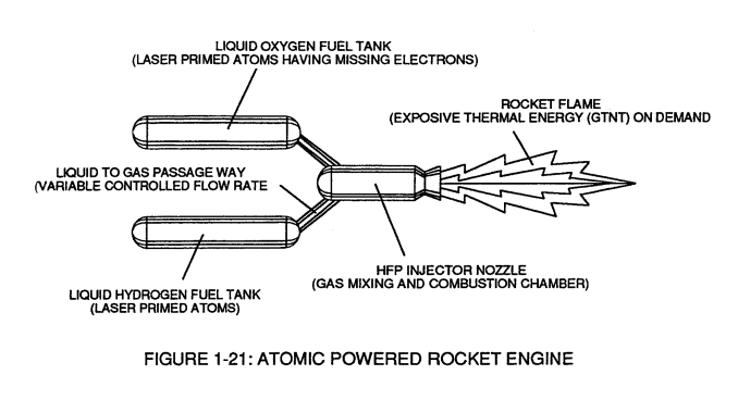](https://stanslegacy.com/uploads/images/gallery/2023-12/SUXp70XxHGRead3q-image-1703011912526.png)Prolonged-rocket-flights carrying heavier payloads is achieved by liquefying the "specially treated” combustible gas ions (laser primed oxygen gas atoms having missing electrons and laser primed hydrogen gas atoms) under pressure in separate fuel tanks affixed to a Rocket Engine, as illustrated in Figure (1-21).**Rocket thrust** is now controlled by the flow rate of the combustible ionized gases entering the combustion chamber of the rocket engine once gas-ignition occurs.
# In Summation The **Hydrogen Fracturing Process** simply triggers and releases **atomic energy** from natural water by allowing highly energized sub-critical combustible gas ions to come together during thermal gas ignition. The **Voltage Intensifier circuit** brings on the "**Electrical Polarization Process**" that switches off the covalent bond of the water molecule without consuming amps.The **Electrical Extraction Circuit** not only decreases the mass size of the combustible gas atoms; but, also, and at the same time produces "**electrical energy**" when the liberated electrons are directed away from the **Hydrogen Gas Gun Assembly**.
The **Hydrogen Fracturing Process** has the capability of releasing **thermal explosive energy** up to and beyond 2.5 million barrels of oil per gallon of water under controlled state
…which simply prevents the formation of the water molecule during thermal gas ignition …releasing thermal explosive energy beyond the normal gas combustion process.The **Hydrogen Fracturing Process** is environmentally safe.
The **Hydrogen Fracturing Process** is design-variable to retrofit to any type of energy consuming devise since the **Hydrogen Gas Gun** can be reduced to the size of an auto spark plug or a gas injector pan of a fighter aircraft or enlarged to form a rocket engine.Prototyping determines operational parameters.
> The **Hydrogen Fracturing Process** is registered and certified under the **Patent Cooperation Treaty Act** via foreign grant license #492680 issued July 10, 1989 and foreign grant license #490606 issued Nov. 15, 1988 by the **United States of America** as to **Hydrogen Fracturing Process** > > U.S. patent #4,826,581 issued May 2, 1989, Electrical Polarization Process > U.S. Patent #4,936,961 issued Iune26, 1990, Resonant Cavity Voltage Intensifier Circuit (VIC) > U.S. Patent 5,149,407 issued Sept 22, 1992, > and other U.S. patents pending under the Patent Cooperation Treaty Act (PCT) Worldwide. > > (see WFC "Patents Granted To Date"). # WFC 420 - Illustrations| [](https://stanslegacy.com/uploads/images/gallery/2023-12/qhtqz9LzDjg4722f-image-1703011664617.png) | [](https://stanslegacy.com/uploads/images/gallery/2023-12/VzsK8hdVflGHQSyd-image-1703011673363.png) |
| [](https://stanslegacy.com/uploads/images/gallery/2023-12/KS1IdCNzwsPJRslu-image-1703011682305.png) | [](https://stanslegacy.com/uploads/images/gallery/2023-12/BVSJKDz1yh7YR7m9-image-1703011690241.png) |
| [](https://stanslegacy.com/uploads/images/gallery/2023-12/l7jnV5JDH3YDsfqc-image-1703011705003.png) | [](https://stanslegacy.com/uploads/images/gallery/2023-12/wYpyHOaHXDoxZiEv-image-1703011741746.png) |
| [](https://stanslegacy.com/uploads/images/gallery/2023-12/OPnNcyNwXCESXxxs-image-1703011752626.png) | [](https://stanslegacy.com/uploads/images/gallery/2023-12/4XkiC7I7LVDpsfmO-image-1703011782177.png) |
| [](https://stanslegacy.com/uploads/images/gallery/2023-12/zsCMBBwfkWoq9neZ-image-1703011792203.png) | [](https://stanslegacy.com/uploads/images/gallery/2023-12/QpGkWk3GM41m99vV-image-1703011803057.png) |
| [](https://stanslegacy.com/uploads/images/gallery/2023-12/xosAehbokL7U71yH-image-1703011813778.png) | [](https://stanslegacy.com/uploads/images/gallery/2023-12/hAAtdFuWmDfeRzsr-image-1703011825328.png) |
| [](https://stanslegacy.com/uploads/images/gallery/2023-12/71dhbrDuuRCV1eVl-image-1703011834325.png) | [](https://stanslegacy.com/uploads/images/gallery/2023-12/NZb1P2WOhS2EsvQw-image-1703011843364.png) |
| [](https://stanslegacy.com/uploads/images/gallery/2023-12/mWCdgZlUkrnjVT96-image-1703011855062.png) | [](https://stanslegacy.com/uploads/images/gallery/2023-12/ZlPtTXE0afQrhW3u-image-1703011864175.png) |
| [](https://stanslegacy.com/uploads/images/gallery/2023-12/LhvbL7jb5G8yJdXG-image-1703011873784.png) | [](https://stanslegacy.com/uploads/images/gallery/2023-12/KjUivZrfBcdhGK1e-image-1703011886920.png) |
| [](https://stanslegacy.com/uploads/images/gallery/2023-12/FGeQGP51lwskQWr7-image-1703011901578.png) | [](https://stanslegacy.com/uploads/images/gallery/2023-12/SUXp70XxHGRead3q-image-1703011912526.png) |
| [](https://stanslegacy.com/uploads/images/gallery/2023-12/6U7M9O7BdJWqS4lF-image-1703011928921.png) |
... recycled to stabilize **Gas-Flame** temperatures
...intermixed to sustain and maintain a Hydrogen **Gas-Flame**
... and used to prevent **Spark-Ignition** of supply gases.
The utilization and recycling of the non-combustible gases allows the **Water Fuel Cell** to become a **Retrofit Energy System**. The **Quenching Circuit Technology** is systematically activated and performed in the following way: # Spark-Ignition Tube **[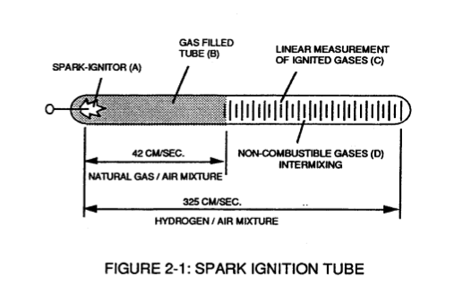](https://stanslegacy.com/uploads/images/gallery/2023-12/KR9aOEnHP6CLPl17-image-1702961637525-53-54.png)Spark-Ignition Tube** (B) is a tubular test apparatus (1/8 diameter) that determines and measures the "**Burn-Rate**" of different types of **Burnable Gases** intermixed with Ambient Air, as illustrated in Figure (2-1). **Spark-Igniter** (A) causes and starts the **Burnable Gas-Mixture** (B) to undergo **Gas-Ignition** which, in turns, supports and allows **Gas Combustion** to take place ... forming and sustaining a **Gas-Flame**. The expanding and moving **Gas-Flame** travels (away from spark-igniter) the linear length of the **gas filled tube** (C) and is "**detected**" and "**measured**" (length between spark-igniter and light-detector) in one second after gas-ignition. The Gas-Ignition Process, now, establishes the "**Burn-Rate**" of a **Burnable Gas-Mixture** in centimeters per second (cm/sec.), as illustrated in Figure (2-2). [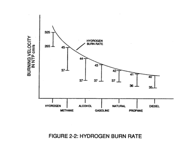](https://stanslegacy.com/uploads/images/gallery/2023-12/Mw6PFaxapv0ewddx-image-1702961644787-54-02.png)Different types of "**Burnable**" **Gas-Mixtures** exposed to the **Gas-Ignition Process** were tested, measured, recorded and systematically arranged as to cm/sec. length, see vertical bar Graph (2-2) again.
The **Gas-Ignition Process** was performed several times to establish the "average" **Burn-Rate** of the **Fuel-Gases** which, in turn, establishes the length of the vertical bars.
# Gas Injection Process Injecting and intermixing an **Non-Combustible Gas** (D) (non-burnable gas) with the '**Burnable** **Gas-Mixture** (B) "changes" or "alters" the gas-mixture "**Burn-Rate**". Increasing the volume-amount of **Non-Combustible Gas** (D) diminishes and/or lowers the "**Burn-Rate**" of the **Gas-Mixture** (B/D) still further. [](https://stanslegacy.com/uploads/images/gallery/2023-12/Mw6PFaxapv0ewddx-image-1702961644787-54-02.png)Progressive and controlled intermixing of the non-combustible gases (B/D) allowed the "Burn-Rate" of Hydrogen to be "lowered" or "adjusted" to "match" or ... co-equal the "Burn-Rate" of other **Fuel-Gases**, see curve line in Figure (2-2). In terms of operational performance, the **Non-Burnable** gas (D) does "Not" support the **Combustion Process** since the **Non-Burnable Gas** (D) "restricts" or "retards" the speed at which the **Oxygen Atom** unites with **Hydrogen Atoms** to cause **Gas Combustion**.The "**Gas Retarding Process**" is, of course, applicable to any type or combination of **Burnable Gases** or **Burnable gas-mixture**.
# Gas Mixing Regulator [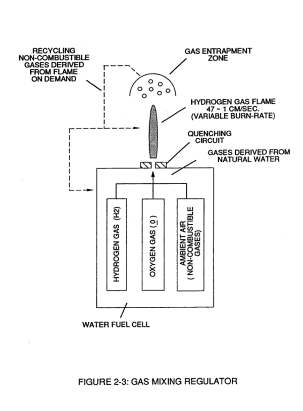](https://stanslegacy.com/uploads/images/gallery/2023-12/vHikAM9oiGf9RNxB-image-1702961652974-54-10.png)Inherently, the **Water Fuel Cell** allows the "**Burn-Rate**" of **Hydrogen** to be "Changed" or "adjusted" from 325 cm/sec. to 42 cm/sec. (Co-equalling Natural Gas Burning levels) since **Non-Combustible Gases** (such as Nitrogen, Argon, and other non-burnable gases) derived from **Ambient Air** dissolved in natural water performs the **Gas Retarding Process**... sustaining and maintaining an **Open-Air Flame** beyond 5000-degrees F, as illustrated in Figure (2-3)
Natural water acts and performs as a "**Gas-Mixing Regulator**" when the **Fuel-Cell** is electrically energized by way of voltage stimulation (Electrical Polarization Process) ... producing a uniform gas-mixture (B/D) regardless of the **Gas Flow-Rate** of the **Fuel-Cell** ... producing a uniform gas-mixture (B/D) only when needed.In quiescent-state, the supply of gases (BID) being released from the water bath is "terminated" and "stopped" when the **Fuel-Cell** becomes "de-energized".
The unused water, of course, remains as a non-burnable liquid.The gases (B/D) above the water bath is "vented" for safety purposes.
# Flame Temperature Adjustment By capturing and recycling the expelled non-combustible gas (D) (derived from and supplied by the water bath) back into the sustained hydrogen gas-flame or **Fuel-Cell** causes the gas-flame temperature to be "changed" or "altered" by way of the **Gas Retarding Process**, as illustrated in Figure (2-4) as to Figure (2-3).| **Gas Retarding Process**, as illustrated in Figure (2-4) [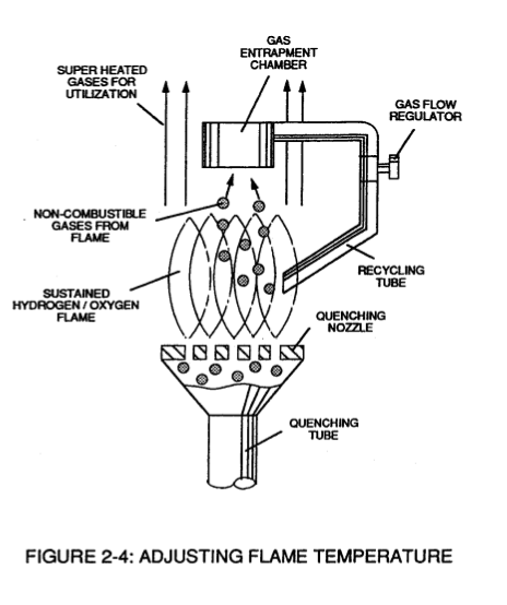](https://stanslegacy.com/uploads/images/gallery/2023-12/gJ9Hcx4XBjg8qG8a-image-1702961662717-54-20.png) | Figure (2-3) [](https://stanslegacy.com/uploads/images/gallery/2023-12/vHikAM9oiGf9RNxB-image-1702961652974-54-10.png) |
Continual feedback of non-combustible gases (D) is, hereinafter, called "**The Gas Combustion Stabilization Process**".
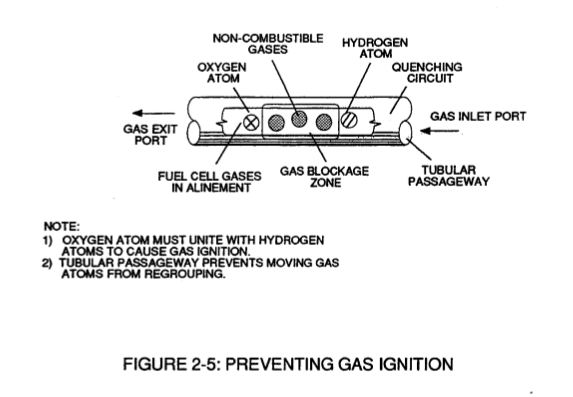
Automatically, the **Gas Combustion Stabilization Process** changes the "**Burn-Rate**" of the **Fuel Cell** gases (B/D) when obtaining the desired gas-flame temperature. # Quenching Circuit **Spark-Ignition** of the **Fuel-Cell** gases (B/D) is prevented when the "**Gas Retarding Process**" is used in conjunction with a "**Quenching Circuit**", as illustrated in Figure (2-3), (2-4), (2-5) and (2-6).| [](https://stanslegacy.com/uploads/images/gallery/2023-12/vHikAM9oiGf9RNxB-image-1702961652974-54-10.png) | [](https://stanslegacy.com/uploads/images/gallery/2023-12/gJ9Hcx4XBjg8qG8a-image-1702961662717-54-20.png) |
| [](https://stanslegacy.com/uploads/images/gallery/2023-12/nddlk062DoN28dzM-image-1702961669650-54-27.png) | [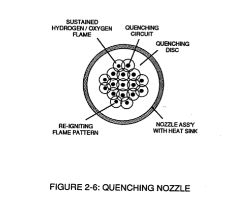](https://stanslegacy.com/uploads/images/gallery/2023-12/7UGJBw4kZB7ddVvy-image-1702961676853-54-34.png) |
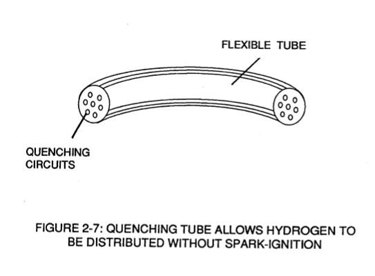
The narrow passageway (at least 1/8 inch long and having a .015 diameter) prevents the moving gas atoms from "Re-Grouping".
The alignment of the Fuel-Cell gases (BID) inside the tubular-passageway is, hereinafter, called "**The Quenching Circuit**".The **Quenching Circuit** "Anti-Spark technique" is "independent" of both **Gas-Velocity** and **Gas-Pressure**.
# Quenching NozzleAdditional Quenching Circuits arranged in a Disc-shape configuration forms a "Quenching Nozzle" when attached to an "Quenching Tube", as illustrated in Figure (2-4) as to Figure (2-6).
| Figure (2-3) [](https://stanslegacy.com/uploads/images/gallery/2023-12/vHikAM9oiGf9RNxB-image-1702961652974-54-10.png) | Figure (2-6) [](https://stanslegacy.com/uploads/images/gallery/2023-12/7UGJBw4kZB7ddVvy-image-1702961676853-54-34.png) |
... preventing **Gas-Oxide** formation, as illustrated in Figure (2-8) as to Figure (2-4).
| Figure (2-8) [](https://stanslegacy.com/uploads/images/gallery/2023-12/nddlk062DoN28dzM-image-1702961669650-54-27.png) | Figure (2-4) [](https://stanslegacy.com/uploads/images/gallery/2023-12/gJ9Hcx4XBjg8qG8a-image-1702961662717-54-20.png) |
Engine temperature remains the same since **The Gas Stabilization Process** is used.
# Gas Grid System **Ambient Air** is the prime source of **Non-Combustible Gases** when the **Air-Gases** are exposed to and passes through an **Open-Air Flame**, as illustrated in Figure (2-10). [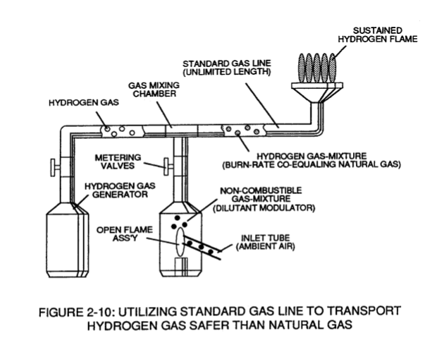](https://stanslegacy.com/uploads/images/gallery/2023-12/et21vo8ebVZK3IO1-image-1702961714634-55-12.png) The **Gas Combustion Process** of the **Gas-Flame** eliminates oxygen and burnable gas atoms from the expelling gases ... producing an endless supply of non-combustible gases. Mixing the "processed" **Air-Gases** with an **Hydrogen Supply Source** sets up **The Gas Retarding Process** ... allowing the **Hydrogen Gas-Mixture** to be transported safely through existing **Gas-Grid System**. # Operational Parameters The utilization and recycling of non-combustible gases, now, renders hydrogen gas as safe as **Natural Gas** or any other **Fuel-Gas** ... allowing the **Water Fuel Cell** to become a **Retrofit Energy System**. [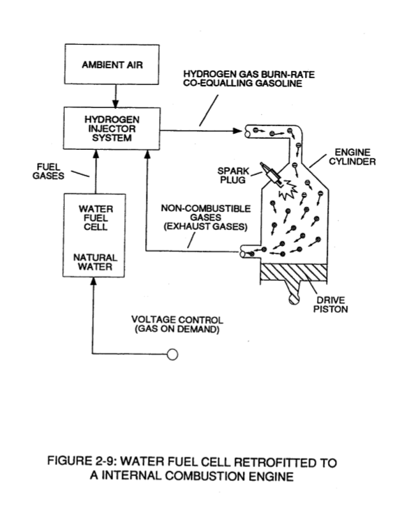](https://stanslegacy.com/uploads/images/gallery/2023-12/hOUajLIPckMkyVlX-image-1702961706589-55-03.png) # WFC 421 - Illustrations| [](https://stanslegacy.com/uploads/images/gallery/2023-12/KR9aOEnHP6CLPl17-image-1702961637525-53-54.png) | [](https://stanslegacy.com/uploads/images/gallery/2023-12/Mw6PFaxapv0ewddx-image-1702961644787-54-02.png) |
| [](https://stanslegacy.com/uploads/images/gallery/2023-12/vHikAM9oiGf9RNxB-image-1702961652974-54-10.png) | [](https://stanslegacy.com/uploads/images/gallery/2023-12/gJ9Hcx4XBjg8qG8a-image-1702961662717-54-20.png) |
| [](https://stanslegacy.com/uploads/images/gallery/2023-12/nddlk062DoN28dzM-image-1702961669650-54-27.png) | [](https://stanslegacy.com/uploads/images/gallery/2023-12/7UGJBw4kZB7ddVvy-image-1702961676853-54-34.png) |
| [](https://stanslegacy.com/uploads/images/gallery/2023-12/owYu2MsSIVcHQztT-image-1702961684839-54-42.png) | [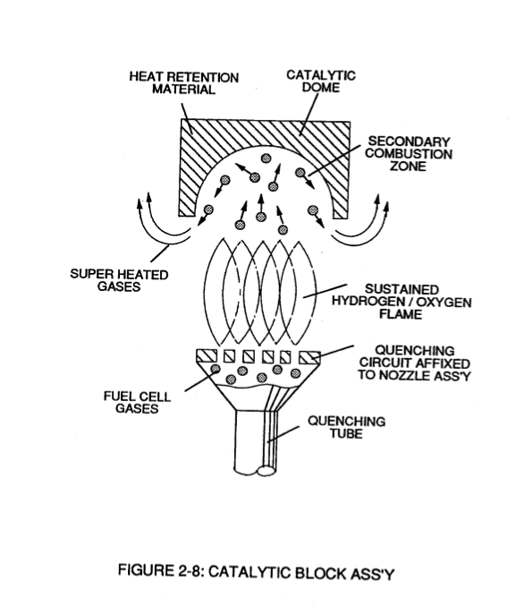](https://stanslegacy.com/uploads/images/gallery/2023-12/EM1naMzXfjT8AXTz-image-1702961692115-54-48.png) |
| [](https://stanslegacy.com/uploads/images/gallery/2023-12/hOUajLIPckMkyVlX-image-1702961706589-55-03.png) | [](https://stanslegacy.com/uploads/images/gallery/2023-12/et21vo8ebVZK3IO1-image-1702961714634-55-12.png) |
| [](https://stanslegacy.com/uploads/images/gallery/2023-12/t2OXEW4fJjav3S1A-image-1702961722022-55-19.png) |
| **Laser Accelerator Assembly** (20) of Figure (3-10) [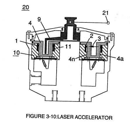](https://stanslegacy.com/uploads/images/gallery/2023-12/0bZIjzhQfoac5KO6-image-1703381224678.png) | **SDP8611 Optoschmitt light receiver** (2) of Figure (3-9) [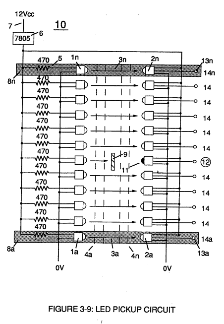](https://stanslegacy.com/uploads/images/gallery/2023-12/eqE5Dz27qkVqIGiU-image-1703374881884.png) |
The peak **wavelength** (3) of Figure (3-9) being transmitted from the infrared emitting diode (led) (1) to the **Optoschmitt receiver** (2) is typically (935 nm) and allows the **Optoschmitt** (2) clock frequency (the speed by which the Optoschmitt changes logic state) to be (100 kHz).
**Optical lens** (4) of Figure (310) redirects and focuses the **transmitted light source** (3) of Figure (3-9) (traveling infrared light waves) to the **Optoschmitt** (2) by passing the light source through a series of **concentric lenses** (4a xxx 4n) of Figure (3-10) which become progressively smaller from the **outer peripheral lens surface** (4a) to the **inner lens surface** (4n). [](https://stanslegacy.com/uploads/images/gallery/2023-12/0bZIjzhQfoac5KO6-image-1703381224678.png)The **spatially concentric lenses** (4a xxx 4n) of Figure (3-10) causes the beam angle of the light source to trigger the **Optoschmitt** (2) beyond the minimum irradiance that is needed to switch the Optoschmitt from **quiescent state** (high logic state I B+ ) to **on-state** (output changing to zero volts).The **Derate linearly** of light intensity is approximately 1.25mWj degree C above 25 degree C at a spatial distance of .500 inches between the **two infrared devices** (1)(2) of Figure (3-9) as to Figure (3-10).
**Transmitted light source** (3) is turned-on when a electrical power source of 5 volts is applied to the **led** (1) through **dropping resister** (5) by way of **voltage regulator** (6) connected to the car **electrical system** (7). Together, the **matched infrared devices** (1)(2) with **optical lens** (4) forms **optical circuit** (8) of Figure (3-9).Grouping additional **optical circuits** (8a xxx 8n) in an inline or linear arrangement, now, forms **Led Pickup Circuit** (10) of Figure (3-9), as shown in Figure assembly (20) of Figure (3-10).
| **Led Pickup Circuit** (10) of Figure (3-9) [](https://stanslegacy.com/uploads/images/gallery/2023-12/eqE5Dz27qkVqIGiU-image-1703374881884.png) | Figure assembly (20) of Figure (3-10) [](https://stanslegacy.com/uploads/images/gallery/2023-12/0bZIjzhQfoac5KO6-image-1703381224678.png) |
Advancing **light-gate** (9) still further performs the same opposite (alternate) logic-state switching in a sequential manner until the advancing **light-gate** (9) reaches the **last optical circuit** (8n).
Reversing the movement of **light gate** (9) performs the same high to low logic switch-function but in reverse sequential order. Reversing the direction of the **light-gate** (9) once again reinstates the original sequential switching order, as illustrated in Figure (3-7) and Figure (3-9).Longevity and reliability of component life is typically 100,000 hours since led pickup circuit (10) of figure (3-9) utilizes no mechanical contacts to perform the sequential logic switch function.
**[](https://stanslegacy.com/uploads/images/gallery/2023-12/0bZIjzhQfoac5KO6-image-1703381224678.png)Light-gate** (9) integrated with **led pickup circuit** (10) make up **Laser Accelerator assembly** (20), as shown in Figure (3-10). **Light-gate** (9) of Figure (3-10) is mechanically linked to the car acceleration pedal by way of **cabling hookup** (22). Opposite placement of the **matched infrared devices** (1)(2) prevents bogus or false triggering of "low" **logic state** (12) during **light-gate displacement** (9a xxx 9n) of Figure (6)(7) and (8). If light emitting diodes (led) (la xxx In) of figure (8) are electrically disconnected from D.C. power supply (6), then **Led Pickup Circuit** (10) outputs are switch to "low" logic state (l2a xxx 12n) which disallows "low" **logic state signal** (12), resulting in a "shut-down" condition to **Hydrogen Gas Control Circuit** (200) of Figure (3-1). [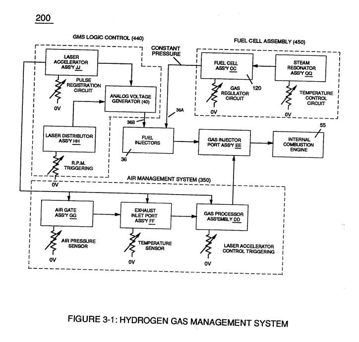](https://stanslegacy.com/uploads/images/gallery/2023-12/2npurKubUvEXMU5s-image-1703381503607.png) Disconnection of **power supply** (6) to **Optoschmitt array** (2a xxx 2n) of Figure (3-9) results in a similar "shut down" condition to **control circuit** (200), as further shown in Figure (3-1).This "shut-down" or "Switch-off" condition helps provide a fail-safe operable **Fuel Cell** (120) of Figure (3-20) by negating acceleration beyond driver's control.
# Acceleration Control Circuit (30) Moving **light-gate** (9) of figure (3-9) in direct relationship to the physical placement of **optical circuits** (8a xxx 8n), sets up a **time variable** (14a xxx 14n) of Figure (3-7) from **optical circuits** (8x) to another **optical circuit** (8xx) and/ or (8xxx) or to (8n) since the triggered **low logic state** (12) of Figure (3-7) and (3-8) moves in direct relationship to the displaced **light-gate** (9), as illustrated in Figure (3-12).| Figure (3-7) [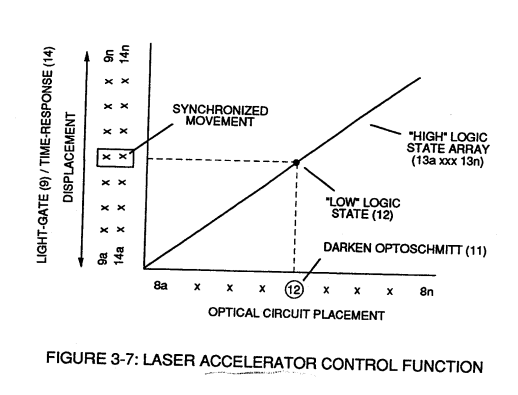](https://stanslegacy.com/uploads/images/gallery/2023-12/TUF7LkkiUSFT4h2x-image-1703374861011.png) | Figure (3-8) [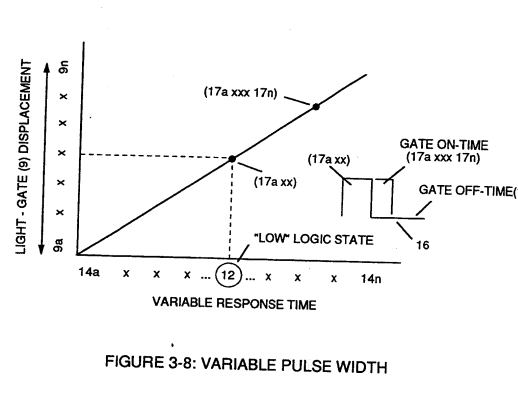](https://stanslegacy.com/uploads/images/gallery/2023-12/pjxVw7assd34zNNX-image-1703374870146.png) |
| Figure (3-9) [](https://stanslegacy.com/uploads/images/gallery/2023-12/eqE5Dz27qkVqIGiU-image-1703374881884.png) | Figure (3-12) [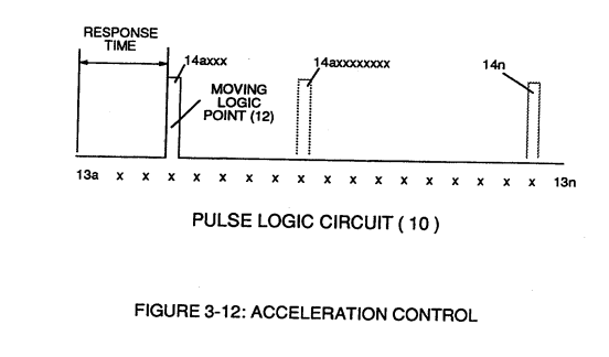](https://stanslegacy.com/uploads/images/gallery/2023-12/bBte9bH1vjrh9pO1-image-1703374892948.png) |
Deflecting (moving) the **light-gate** (9) to **position** (8n) takes longer in **response-time** (14n) than deflecting the light-gate to position (8x) and/or (8xx) or (8xxxx).
This variable **response-time** (14axx ... 12 ... xxI4n) or **signal output** (15) of Figure (3-5) is, now, electrically transmitted to **Acceleration Control Circuit** (30) of Figure (3-5) since **Laser Accelerator Assembly** (20) of figure (3-10) converts **mechanical displacement** (9a xxx 9n) to **electrical time-response** (14a xxx 14n) of Figure (3-7) by linearly moving (forward and/or reverse direction) "low" **logic state signal** (12) in a array of "high" logic state **output signals** (13a xxx 13n), as further illustrated in Figure (3-8) and Figure (3-12).| Figure (3-7) [](https://stanslegacy.com/uploads/images/gallery/2023-12/TUF7LkkiUSFT4h2x-image-1703374861011.png) | Figure (3-5)[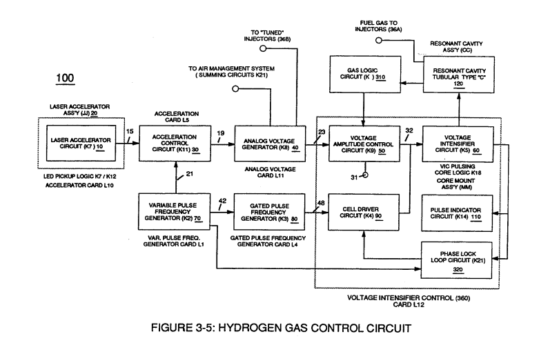](https://stanslegacy.com/uploads/images/gallery/2023-12/vFSFXV3sntA7ICZs-image-1703375068946.png) |
| Figure (3-8) [](https://stanslegacy.com/uploads/images/gallery/2023-12/pjxVw7assd34zNNX-image-1703374870146.png) | Figure (3-12) [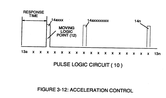](https://stanslegacy.com/uploads/images/gallery/2023-12/5uNuLwkNkx6jxXkA-image-1703375156797.png) |
Circuit (30) electronically and automatically scans **output signal-array** (14axxx ... 12 ... xx14n) (15) until **circuit** (30) locates, **momentarily registers**, and translates **response-time** (14a xxx ... 12) into a **variable unipolar pulse** (17/18) of Figure (3-8).
The sweeping action of the **scanning circuit** (30) always starts from **position** (9a) and moves **point** (8ax) to **point** (8axxx) of Figure (3-9) (3-12) until **logic-point** (12) is detected. Once **logic signal** (12) is detected, the sweeping action toggles and recycles back to **start-position** (9a). This toggling (*flip back*) action electronically determines **variable time-response** (14a xxx) regardless of wherever logic point (12) is being momentarily displaced within **circuit array** (13a xxx 13n). **[](https://stanslegacy.com/uploads/images/gallery/2023-12/pjxVw7assd34zNNX-image-1703374870146.png)Toggling action** at full-scale **deflection** (13a xxx 13n) occurs in the range of (10) kHz or above and thus, allows instant response to driver's acceleration demands. **Toggling-time** (scanning-time) is directly synchronized to **light gate** (9) displacement which, in turns, **circuit** (30) further sets up and establishes a given **pulse shape** (16) of Figure (3-8). **Circuit** (30) continues to increase **pulse width** (17axxxx) of Figure (3-8) as the monitored (*detected by < scanning*) **toggling-time** (14a xxxx ... 12) increases when **logic-point** (12) moves farther away from **start-position** (9a) to **stop-position** (9n), as further shown in Figure (3-13) as to Figure (3-12).**Pulse width** (17a xxx 17n) diminishes when **logic-point** (12) reverses direction to start .. **position** (9a).
| Figure (3-12)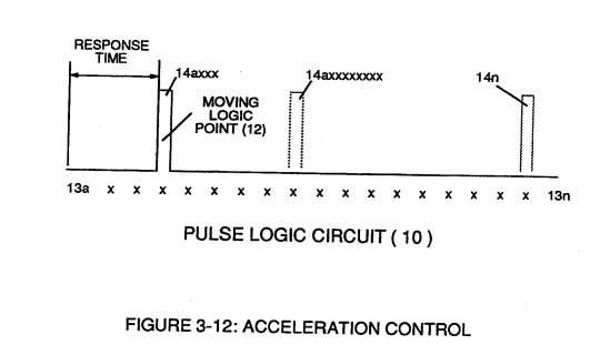 | Figure (3-13)[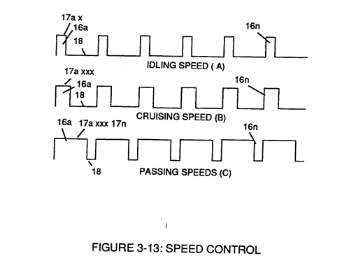](https://stanslegacy.com/uploads/images/gallery/2023-12/BP6hCkX2nps5ADCT-image-1703375624884.png) |
Finally, **circuit** (30) reproduces the **variable controlled pulse-shape** (16) in a continuous **repetitive manner** (16a xxx 16n) of Figure (3-13) and electrically transmits the resultant **pulse-train signal** (19) to **Analog Voltage Circuit** (40), as shown in Figure (3-5).
| Figure (3-13) [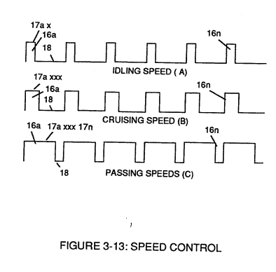](https://stanslegacy.com/uploads/images/gallery/2023-12/kaBCr5103gLcMT1t-image-1703194915396.png) | **Analog Voltage Circuit** (40), as shown in Figure (3-5) [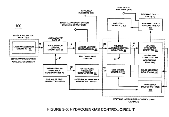](https://stanslegacy.com/uploads/images/gallery/2023-12/YkkFL3H6bzsH65A5-image-1703194897766.png) |
In retrospect to **engine performance** (*gas pedal attenuation*) (21) of Figure (3-10), a wider **pulse width** (17a xxx) of Figure (3-13C) increases (*accelerates*) engine R.P.M.; whereas, smaller **pulse-width** (17ax) reduces (de-accelerates) engine R.P.M .. Cruising speed (3-13B) of Figure (3-13) is simply accomplished when pulse width remains constant.
Incoming **clock pulse** (21a xxx 21n) of Figure (3-16) originating from **Pulse Frequency Generator** (70) of| Figure (3-16) [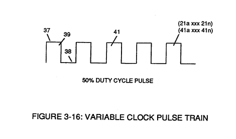](https://stanslegacy.com/uploads/images/gallery/2023-12/uPM4NAOKxNgpKeiA-image-1703375884091.png) | Figure (3-5) [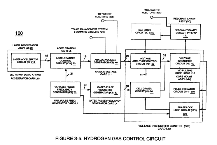](https://stanslegacy.com/uploads/images/gallery/2023-12/pkENicyNmypUexcX-image-1703375903506.png) |
The resultant **clock pulse** (21) of Figure (3-16) as to Figure (3-5) is always adjusted to exceed driver's response time to allow for instant acceleration control.
# Analog Voltage generator (40) The generated **digital signal** (19) being electrically transmitted from **accelerated control circuit** (30) of Figure (3-5) is, now, electronically detected, translated, and converted into a **analog voltage signal** (22) which is continuously proportionate to **input signal** (19) by **Analog Voltage Generator Circuit** (40) of Figure (3-5). [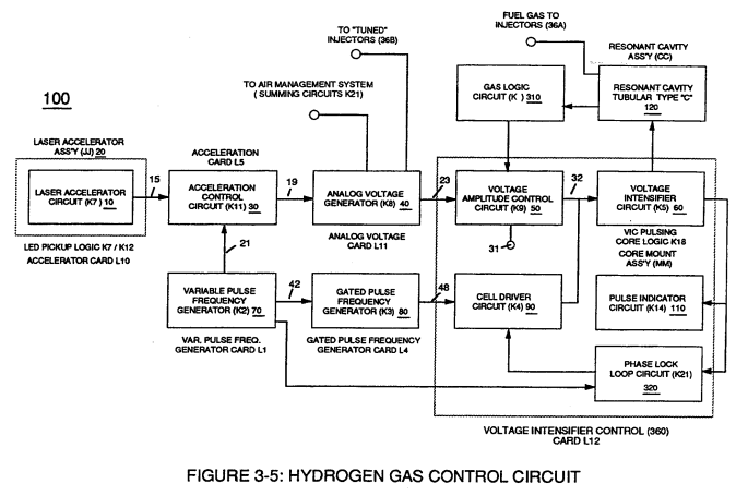](https://stanslegacy.com/uploads/images/gallery/2023-12/d5x6lw5jRAJT48i1-image-1703195613050.png) The newly formed **analog signal** (22) of Figure (3-14) is a voltage level signal that varies continuously in both time and amplitude to produce a voltage level which is directly proportional to the physical change in **pulse train** (100 xxx 16n) of Figure (3-13).| Figure (3-13) [](https://stanslegacy.com/uploads/images/gallery/2023-12/kaBCr5103gLcMT1t-image-1703194915396.png) | Figure (3-14) [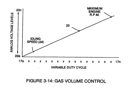](https://stanslegacy.com/uploads/images/gallery/2023-12/prG7V9Hd24ooi89W-image-1703195335274.png) |
The resultant and varied **voltage level** (22a xx) varies smoothly over a continuous range of **voltage valves** (22a xxx 22n) *rather than in discrete steps*, as illustrated in linear graph (23) of Figure (3-14).
In terms of functional-ability and purpose, **analog circuit** (40) of Figure (3-5) provides a variable (controlled) **voltage output** (23) in direct relationship to light gate (9) displacement which, in turns, sets up and controls **Resonant Action** (160) of Figure (3-23) that produces **Fuel Gases** on demand.
**[](https://stanslegacy.com/uploads/images/gallery/2023-12/prG7V9Hd24ooi89W-image-1703195335274.png)Analog circuit** (40) also calibrates both **engine idling speed** (22ax) and **maximum engine R.P.M.** (22a xxx 22n) by adjusting and maintaining a predetermined or given **low** (24) and **high** voltage levels respectively, as further illustrated in Figure (3-14).**Voltage valves** or **levels** (22a xxx 22n) simply controls the applied voltage potential across **Resonant Cavity Assembly** (120) of Figure (3-22) through **voltage amplitude control circuit** (50) of Figure (3-5) which is is electrically linked to **primary coil** (26) of Figure (3-22) of **Voltage Intensifier Circuit** (60) of Figure (3-5).
| Figure (3-22) [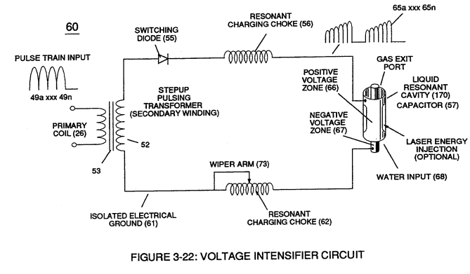](https://stanslegacy.com/uploads/images/gallery/2023-12/8ATrN3YcXfGXz0Kt-image-1703196300438.png) | Figure (3-5) [](https://stanslegacy.com/uploads/images/gallery/2023-12/d5x6lw5jRAJT48i1-image-1703195613050.png) |
| Figure (3-21) [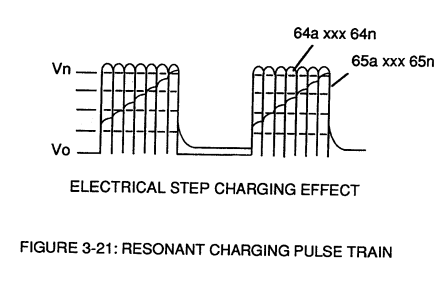](https://stanslegacy.com/uploads/images/gallery/2023-12/uie7yJbd501dcf86-image-1703197617452.png) | Figure (3-22) [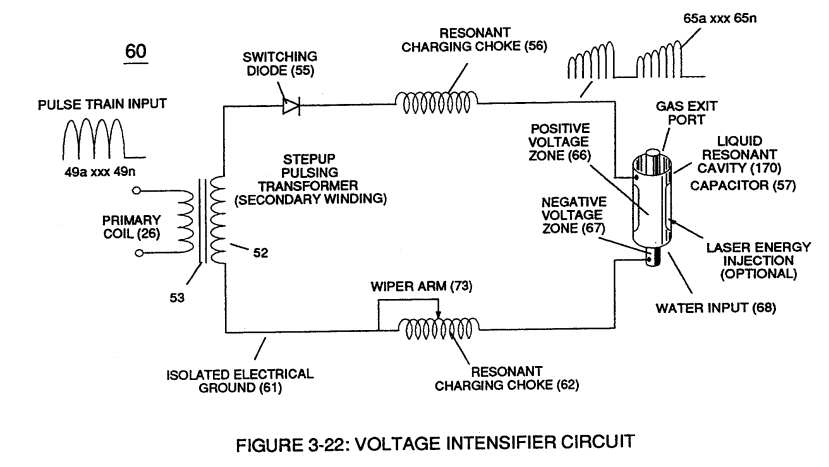](https://stanslegacy.com/uploads/images/gallery/2023-12/QHMK3ysi5cLB805A-image-1703197630289.png) |
**Regulator stage** (27) of **circuit** (50) converts **battery voltage potential** (29) of Figure (3-6) via **electrical terminal** (31) of Figure (3-5) as to Figure (3-6) into a **analog voltage signal** (32) of Figure (3-15) which corresponds to but is **electrically isolated** (*crossover voltage from two separate power supplies*) from incoming **gas volume signal** (23) of Figure (3-14), as shown in Figure (35).
**Variable voltage range** (32a xxx 32n) from **one** (1) up to **twelve** (12) volts (regulating battery voltage) is applied across **primary coil** (26) of **Voltage Intensifier Circuit** (60) of Figure (3-21). Second **regulator stage** (28) simply acts and function as a **gas regulator** (33) by preventing **Fuel Gas** production beyond a predetermined **gas pressure level** (34) of Figure (3-15) during **Fuel Cell** operations and, as such, maintains constant gas pressure to **Fuel Injectors** (36) of Figure (3-1) regardless of engine performance (R.P.M. response).If for example, **Fuel Gas** production is greater than demand, then, **analog signal** (32) is reduced to proper **voltage level** (35) (voltage level directly determines gas pressure via **Resonant Action**) required to maintain **gas pressure** (34).
Conversely, **analog signal** (32) is always allowed to exceed **voltage level** (35) during **injection** (36) of Figure (3-1) until **gas-point** (34) is reached.In cases where **linear voltage** (32) drops (descending value) below **gas-point** (35) then **gas regulator stage** (28) increases **voltage amplitude** (32a xxx 32n) (analog voltage) to **voltage point** (35).
If **gas pressure** (34a xx) should exceed **gas point** (35) during injector off-time, **gas pressure release valve** (75) of Figure (3-24) (**gas venting** 37 of Figure 3-15) expels **Fuel gases** (88) until **gas point** (34) is either reached or a delay timing circuit activates **Safety Control Circuit** (14) of Figure (3-6) which, in turns, switches off or disconnects **applied electrical power** (28) to **Fuel Cell electrical system** (400) of Figure (3-6).| Figure (3-15) [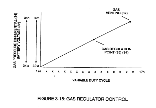](https://stanslegacy.com/uploads/images/gallery/2023-12/q8NhrnLpRbNYf6ta-image-1703197371585.png) | Figure (3-6) [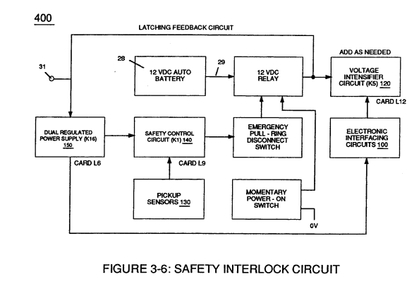](https://stanslegacy.com/uploads/images/gallery/2023-12/svIAaiYbAQpJY3rv-image-1703197390102.png) |
| Figure (3-1) [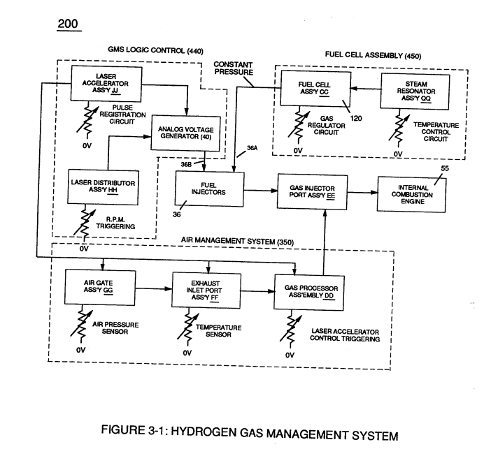](https://stanslegacy.com/uploads/images/gallery/2023-12/QW9gvbrkDyzcsRDF-image-1703197200823.png) | Figure (3-24) [](https://stanslegacy.com/uploads/images/gallery/2023-12/1WXhsCSuTnngaFfo-image-1703197217269.png) |
In terms of operability, **Laser Accelerator Assembly** (20) of Figure (3-5) is, now, attenuating **battery voltage potential** (32a xxx 32n) which is electrically connected to **Voltage Intensifier Circuit** (60) of Figure (3-5).
[](https://stanslegacy.com/uploads/images/gallery/2023-12/d5x6lw5jRAJT48i1-image-1703195613050.png) # Variable Pulse Frequency Generator (70) **Circuit** (70) of Figure (3-5) is a **multi pulse-frequency generator** which produces several clock pulses (*simultaneously*) **having different pulse-frequency** but maintaining a 50% duty cycle pulse (39) configuration, as illustrated in Figure (3-16).| Figure (3-5) [](https://stanslegacy.com/uploads/images/gallery/2023-12/d5x6lw5jRAJT48i1-image-1703195613050.png) | Figure (3-16) [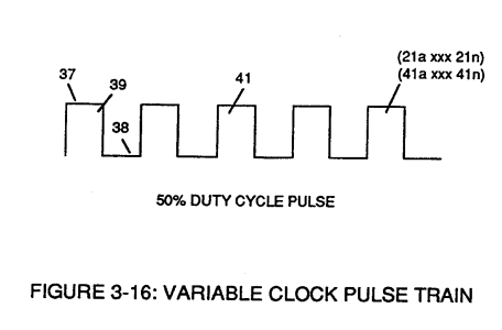](https://stanslegacy.com/uploads/images/gallery/2023-12/9eo48JVGQNzatQ86-image-1703198042496.png) |
Newly formed **gated duty pulse** (45) is proportional to the physical change in **pulse train** (44a xxx 44n) when **circuit** (80) is adjusted for calibration purposes.
**Pulse train** (44a xxx 44n) becomes **widened** while **pulse off-time width** (43) becomes **smaller**, simultaneously.
Conversely, opposite **pulse shaping occurs** when **circuit** (80) of Figure (3-5) is **calibrated in reverse** **order**.
# Cell Driver Circuit (90) In either case, the resultant or varied **pulse train** (47a xxx 47n) (*calibration of 44a xxx 44n*) becomes **incoming gated pulse signal** (48) of figure (3-5) to **cell driver circuit** (90) of Figure (3-5) which performs a switching function by switching "**off**' and "**on**" electric ground being applied to **opposite side** (48) of **primary coil** (26) of Figure (3-19).| Figure (3-18) [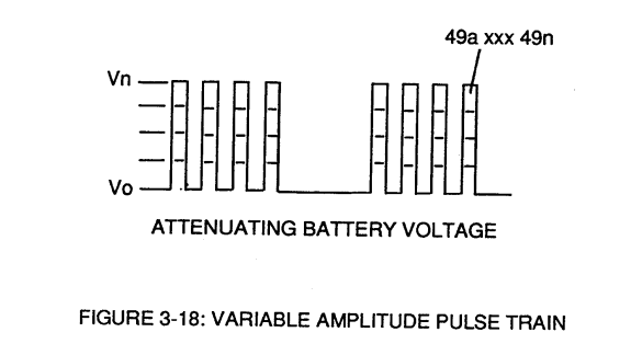](https://stanslegacy.com/uploads/images/gallery/2023-12/perOMBdYqG5zfDB2-image-1703200544967.png) | Figure (3-19) [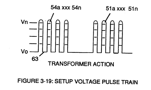](https://stanslegacy.com/uploads/images/gallery/2023-12/UateQAwSqhsH4mKF-image-1703200555466.png) |
However, each **pulse train** (47) (49) are electrically isolated from each other.
Only voltage cross-over from regulated **power supply** (150) of Figure (3-6) to **battery supply** (28) occurs, as illustrated in Figure (3-6).| Figure (3-6)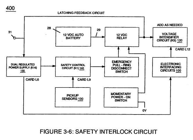 | Figure (3-5) |
| Figure (3-15) [](https://stanslegacy.com/uploads/images/gallery/2023-12/q8NhrnLpRbNYf6ta-image-1703197371585.png) | Figure (3-18) [](https://stanslegacy.com/uploads/images/gallery/2023-12/perOMBdYqG5zfDB2-image-1703200544967.png) |
| Figure (3-19) [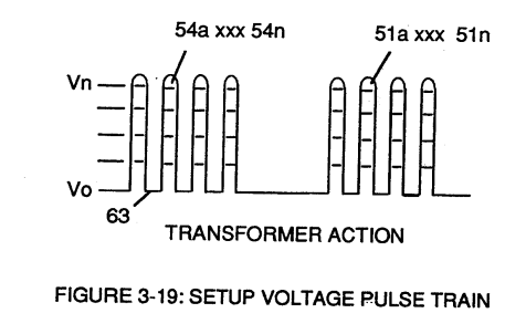](https://stanslegacy.com/uploads/images/gallery/2023-12/ojTv41ralWh4qvQC-image-1703203837958.png) | Figure (3-22) [](https://stanslegacy.com/uploads/images/gallery/2023-12/K7QoIRjYjGqOS8C3-image-1703201617139.png) |
**Analog voltage signal** (32a xxx 32n) of Figure (3-15) allows **pulse train** (51a xxx 51n) **voltage amplitude** (V0 xxx Vn) of Figure (3-19) to vary from **one** up to **twelve** volts *(battery supply 28 of Figure 3-6* by attenuating **Laser Accelerator circuit** (10) of Figure (3-5) via **Hydrogen Gas Control Circuit** (100).
| Figure (3-15) [](https://stanslegacy.com/uploads/images/gallery/2023-12/q8NhrnLpRbNYf6ta-image-1703197371585.png) | Figure (3-5) [](https://stanslegacy.com/uploads/images/gallery/2023-12/d5x6lw5jRAJT48i1-image-1703195613050.png) |
**Variable pulse frequency generator** (70) of Figure (3-5) varies and adjusts **pulse frequency** (63) *(50% duty cycle pulse)* while **gated pulse frequency generator** (80) of Figure (3-5) varies and adjusts **pulse width** (54a xxx 54n).
These controlled and variable pulse features are, now, translated to **Resonant Charging pulse train** (65a xxx 65n) of Figure (3-21) via **Unipolar pulse train** (64a xxx 64n) of Figure (3-20) during **Resonant Action** (160) of Figure (3-26) when signal coupling is applied across **Resonant Cavity** (170) of Figure (3-24) via **positive voltage zone** (66).| Figure (3-21) [](https://stanslegacy.com/uploads/images/gallery/2023-12/qZcJcpsQWujxY3uB-image-1703202650133.png) | Figure (3-20) [](https://stanslegacy.com/uploads/images/gallery/2023-12/1uHRCvzqaVhAKGH6-image-1703204498070.png) |
| Figure (3-26) [](https://stanslegacy.com/uploads/images/gallery/2023-12/JEtePO4SKkPGZWRI-image-1703203395676.png) | Figure (3-24) [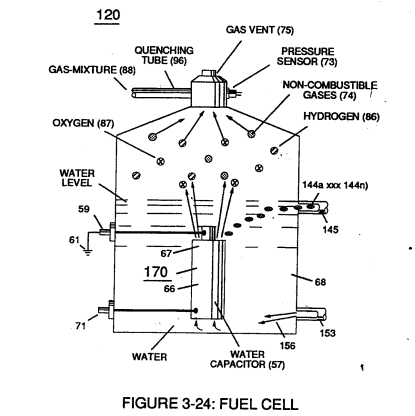](https://stanslegacy.com/uploads/images/gallery/2023-12/SfsY9Ms8MRP5eM0o-image-1703197304479.png) |
**Negative electrical voltage potential** (61) of **pulse wave** (65a xxx 65n) of Figure (3-21) is simultaneously applied to **negative voltage zone** (67) via **Resonant Charging Choke** (62) of Figure (3-22) which is electrically linked to opposite end of **Primary Coil** (26).
The resultant **signal coupling** ( 65a xx 65n ) of Figure (3-21) is accomplished since **primary coil** (26), **pulsing core** (53), **secondary coil** (52), **switching diode** (55), **resonant charging choke** (56), **resonant cavity assembly** (170), **natural water** (68), and **variable resonant charging choke** (62) forms **Voltage Intensifier Circuit** (60) of Figure (3-22), as illustrated in Figure (3-22) as to Figure (3-23).
| Figure (3-22) [](https://stanslegacy.com/uploads/images/gallery/2023-12/K7QoIRjYjGqOS8C3-image-1703201617139.png) | Figure (3-23) [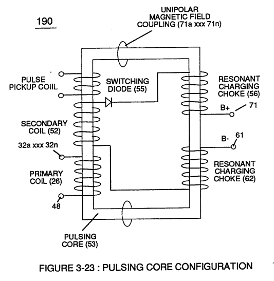](https://stanslegacy.com/uploads/images/gallery/2023-12/Tus1Xr1U62DJCsDx-image-1703201534713.png) |
**Negative electrical ground** (61) of **voltage Intensifier circuit** (60) of Figure (3-22) is electrically isolated from **primary electrical ground** (48) of Figure (3-22).
**Pulsing transformer** (26/52) of Figure (3-22) steps up voltage amplitude or **voltage potential** (Vo xxx Vn) of Figure (3-19) during pulsing operations. **Primary coil** (26) is electrically isolated (*no electrical connection between primary 26 and secondary coil)* to form **Voltage Intensifier Circuit** (60) of Figure (3-22). Voltage amplitude or **voltage potential** (Vo xxx Vn) is increased when **secondary coil** (52) is wrapped with more turns of wire.**Isolated electrical ground** (61) prevents electron flow from **input circuit ground** (48).
**[](https://stanslegacy.com/uploads/images/gallery/2023-12/K7QoIRjYjGqOS8C3-image-1703201617139.png)Switching diode** (55) of Figure (3-22) not only acts as a blocking diode by preventing electrical "**shorting**" to **secondary coil** (52) during **pulse off-time** (69) of Figure (3-20) since **diode** (55) "only" conducts electrical energy in the direction of schematic arrow; but, also, and at the same time functions as an **electronic switch** which opens **electrical circuit** (60) during **pulse off-time** ...allowing magnetic fields of both **inductor coils** (56/57) to collapse ... forming **pulse train** (64a xxx 64n).**Resonant charging choke** (56) in series with **Excitor-Array** (160) of Figure (25) forms an **inductor-capacitor circuit** (180) of Figure (3-28) since **Excitor-Array** (66/67) acts and performs as a capacitor (*dielectric liquid between opposite electrical plates*) during pulsing operations.
[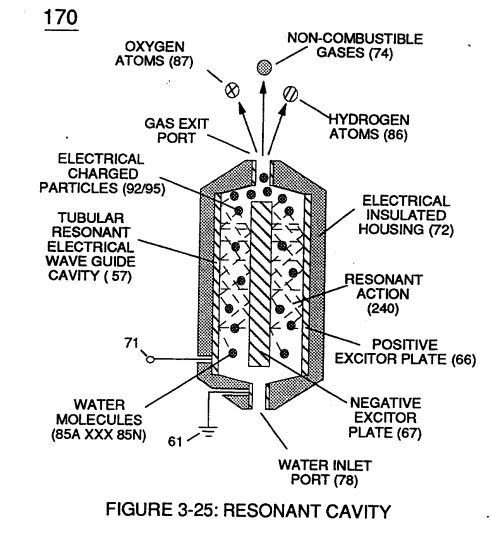](https://stanslegacy.com/uploads/images/gallery/2023-12/jmc1Z2WkjHNbWiZ6-image-1703201429384.png)The **dielectric properties** (*insulator to the flow of amps*) of **natural water** (68) of Figure (3-28) as to Figure (3-26) > *(dielectric constant of water being 78.54 @ 20C in 1-atm pressure)* between **electrical plates** (66/67) forms **capacitor** (57), as illustrated in (170) of Figure (3-25).| Figure (3-26) [](https://stanslegacy.com/uploads/images/gallery/2023-12/JEtePO4SKkPGZWRI-image-1703203395676.png) | Figure (3-28) [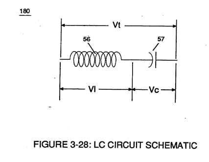](https://stanslegacy.com/uploads/images/gallery/2023-12/8IJsOVAmLG4LJk6U-image-1703203073889.png) |
Water now becomes part of **Voltage Intensifier circuit** in the form of "**resistance**" between **electrical ground** (67) and **pulse-frequency positive potential** (66) ... helping to prevent electron flow within **pulsing circuit** (60) of Figure (3-22).
**Inductor** (56) and **capacitor** (57) properties of LC circuit (180) is therefore "**tuned**" to resonate at a given frequency. **Resonant frequency** (63) of Figure (3-19) can be raised or lowered by changing the **inductance** (56) and/or **capacitance** (57) **valves**.The established **resonant frequency** is, of course, independent of voltage amplitude, as illustrated in Figure (3-21) as to Figure (3-18).
| Figure (3-21) [](https://stanslegacy.com/uploads/images/gallery/2023-12/qZcJcpsQWujxY3uB-image-1703202650133.png) | Figure (3-18) [](https://stanslegacy.com/uploads/images/gallery/2023-12/perOMBdYqG5zfDB2-image-1703200544967.png) |
The impedance of **inductor** (56) and **capacitor** (57) in series, Z series is given by (Eq 1)
[](https://stanslegacy.com/uploads/images/gallery/2023-12/6bTQI1dpHoy0l7Xk-image-1703202839633.png)where **Resonant frequency** (63) of LC circuit in series is given by (Eq 4)
[](https://stanslegacy.com/uploads/images/gallery/2023-12/m9WaOO0dqMhRUide-image-1703202762309.png)Ohm's law of LC circuit (180) of Figure (3-28) in series is given by (Eq 5)
[](https://stanslegacy.com/uploads/images/gallery/2023-12/yGrIzleU35BEaBbL-image-1703202777342.png)The voltage across **inductor** (56) or **capacitor** (57) is greater than **applied voltage** (49) of Figure (3-18).
| Figure (3-18) [](https://stanslegacy.com/uploads/images/gallery/2023-12/perOMBdYqG5zfDB2-image-1703200544967.png) |
At frequency close to resonance, the voltage across the individual components is higher than **applied voltage** (49), and, at resonant frequency, the **voltage** (Vt) of Figure (3-28) across both **inductor** and the **capacitor** are *theoretically infinite*.
However, **physical constraints** of components and circuit interaction prevents the voltage from reaching infinity.
The **voltage** (VI) across **inductor** (56) is given by equation (Eq 6)
[](https://stanslegacy.com/uploads/images/gallery/2023-12/0S6vXBrg4ZRYjrkH-image-1703202464751.png)**Voltage** (Vc) of Figure (3-28) across the **capacitor** is given by (Eq 7)
[](https://stanslegacy.com/uploads/images/gallery/2023-12/o65BVW3T4uncBvSv-image-1703202477600.png) During resonant interaction, the **incoming unipolar pulse train** (64a xxx 64n) of Figure (320) as to Figure (3-21) produces a **step charging voltage effect** across **excitor-array** (66/67) (57) as so illustrated in Figure (3-21).| Figure (3-21) [](https://stanslegacy.com/uploads/images/gallery/2023-12/qZcJcpsQWujxY3uB-image-1703202650133.png) |
**Voltage intensity** increases from **zero** "**ground-state**" to a **high positive voltage potential** in an progressive function.
Once **voltage-pulse** (64) is terminated or switch-off, **voltage potential** returns to "**ground-state**" (61) or near ground-state *(**diode** 55 maintains voltage charged across capacitor 57)* to start the voltage deflection process over again as pulse train (64a xxx 64n) continues to be duplicated.
"Voltage intensity or level across **excitor array** (57) can *exceed 20,000 volts* due to **circuit** (60) interaction and is directly related to **pulse train** (64a xxx 64n) **variable amplitude** input.
**Inductor** (56) is made of or composed of **resistive wire** to further restrict D.C. current flow beyond **inductance reaction** (Xl), and, is given by (Eq 8) [](https://stanslegacy.com/uploads/images/gallery/2023-12/d2Puqn7VvWKdh4XB-image-1703202206972.png) **[](https://stanslegacy.com/uploads/images/gallery/2023-12/K7QoIRjYjGqOS8C3-image-1703201617139.png)Variable inductor-coil** (62) of Figure (3-22), similar to **inductor** (56) connected to **opposite polarity voltage zone** (67) further inhibits electron movement or **deflection** within **voltage intensifier circuit** (60).**Movable wiper arm** (73) of Figure (3-22) fine "tunes" "**resonant action**" during pulsing operations.
**Inductor** (62) in relationship to **inductor** (56) electrically balances the **opposite electrical potential** across **voltage zone (**66/67).
Since **pickup coil** (52) is also composed of or made of **resistive wire-coil**, then, **total circuit resistance** is given by (Eq 9)
[](https://stanslegacy.com/uploads/images/gallery/2023-12/Ckks49Ih0Dt6GhuX-image-1703201978946.png)where, RE is the **dielectric constant** of natural water.
Ohm's law as to **applied electrical power**, which is (Eq 10)
[](https://stanslegacy.com/uploads/images/gallery/2023-12/1AudiDYWkp7BubDT-image-1703201955646.png) where, (Eq 11) [](https://stanslegacy.com/uploads/images/gallery/2023-12/lLpTWNFW6aGZp7eV-image-1703201934685.png) Whereby,**electrical power** (P) is an linear relationship between two variables, **voltage** (E) and **amps** (I).
[](https://stanslegacy.com/uploads/images/gallery/2023-12/Tus1Xr1U62DJCsDx-image-1703201534713.png)Amp restriction *beyond* "**resonant action**" occurs when **unipolar magnetic field coupling** (71) of Figure (3-23) is allowed to simultaneously drop (*pulsating magnetic field*) across **both** **resonant charging chokes** (56/62) during pulsing operations since **electron mass** is an **electromagnetic entity** which is **subject to inductor fields** (56/62) produced by **pulsating magnetic field** (71a xxx 71n) of Figure (3-23).**Amp leakage** (*electron coupling to water*) **to water bath** (68) of Figure (3-24) is further prevented by encapsulating **resonant cavity** (57) in **delrin material** (72) of Figure (3-25) which is an electrical insulator to high voltage.
| Figure (3-24) [](https://stanslegacy.com/uploads/images/gallery/2023-12/1WXhsCSuTnngaFfo-image-1703197217269.png) | Figure (3-25) [](https://stanslegacy.com/uploads/images/gallery/2023-12/jmc1Z2WkjHNbWiZ6-image-1703201429384.png) |
**Delrin material** (72) **insulator value** remains intact since insulation material (72) is resilient to water absorption.
Inherently, then, **pulsing core** (53) of Figure (3-23) aids amp restriction while **voltage intensifier circuit** (190) is being "**tuned**" (*adjusting pulse train 49a xxx 49n pulse-frequency 63 via pulse frequency generator 70 of figure 3-5*) to match the resonant frequency properties of **water bath** (68) of Figure (3-22), as illustrated in **Fuel Cell** (120) of Figure (3-24).| Figure (3-22) [](https://stanslegacy.com/uploads/images/gallery/2023-12/K7QoIRjYjGqOS8C3-image-1703201617139.png) | Figure (3-23) [](https://stanslegacy.com/uploads/images/gallery/2023-12/Tus1Xr1U62DJCsDx-image-1703201534713.png) |
| Figure (3-22) [](https://stanslegacy.com/uploads/images/gallery/2023-12/K7QoIRjYjGqOS8C3-image-1703201617139.png) | Figure (3-27) [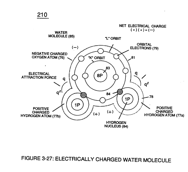](https://stanslegacy.com/uploads/images/gallery/2023-12/X69aZJeEKE3sC7yr-image-1703201640663.png) |
**Voltage potential** (65) is an "unaltered" or "unchanged" energy-state when "**electron movement**" or "**electron deflection**" is prevented or restricted within **electrical circuit** (190) of Figure (3-23).
| Figure (3-22)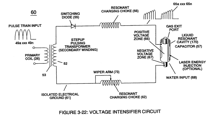 | Figure (3-23)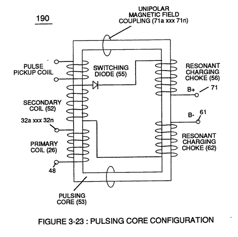 |
These electrical "**forces**" are known as ''**voltage fields**" and can exhibit either a **positive** (66) or **negative** (67) electrical charge.
Likewise, **Ions** or **charged particles** (*atoms having missing or sharing electrons between unlike atoms*) within **electrical circuit** (60) having unlike electrical charges are attracted to each other. **Ions** or **particle** **mass** having the same or like electrical charges will **move away** from one another, as illustrated in (220) of Figure (3-29).Furthermore, electrical charged **ions** or **particles** can move toward stationary voltage fields or **voltage zones** (66/67) of opposite polarity, and, is given by **Newton's second law** (Eq 12)
[](https://stanslegacy.com/uploads/images/gallery/2023-12/o7n7q3jbD3GdVPg3-image-1703232231619.png) Where, the **acceleration** (A) of a **particle mass** (M) acted on by a **net force** (F).Whereby, net force (F) is the "electrical attraction force" (qq') between opposite electrically charged entities (210) of Figure (3-27), and, is given by Coulomb's law (Eq 13)
[](https://stanslegacy.com/uploads/images/gallery/2023-12/tX4hAL0Cj88g0P45-image-1703232254437.png)Whereas, difference of potential between two charges is measured by the work necessary to bring the charges together, and is given by (Eq 14)
[](https://stanslegacy.com/uploads/images/gallery/2023-12/y0mkeGwuGl3kVn4p-image-1703232346301.png)The potential at a point to a **charge** (q) at a **distance** (R) in a medium whose **dielectric constant** is (e).
# Electrically Charged Water Molecule [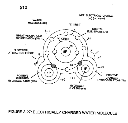](https://stanslegacy.com/uploads/images/gallery/2023-12/tgj1TAs4iQMFjqTd-image-1703376101819.png)Atomic structure of an **atom** (76) and (77) of Figure (3-27) exhibits two types of electrical charged mass entities, **orbital electrons** (79) having **negative electrical charges** ( - ) and a **nucleus** (84) (at least one proton) having a **positive electrical charge** ( + ). > The **positive electrical charge** of the nucleus equals the sum total of all **negative electrical charged electrons** when the atom is in "**stable-state**." In stable state or normal-state, the number of electrons equals the number of protons to give the atom "**no**" net electrical charge. ---Whenever one or more electrons are "**dislodged**" from the atom, the atom takes-on a net positive electrical charge and is called a **positive ion**.
If a electron combines with a stable or normal atom, the atom has a **net negative charge** and is called a **negative ion.****Voltage potential** (65) within electrical **circuit** (60) can cause one or more **electrons** (79) to be dislodged from the **water molecule atom** (85) of Figure (3-26) due to **opposite electrical polarity attraction** (qq') of Figure (3-29) between unlike charged entities, as shown in (160) of Figure (326) as to **Newton's** and **Coulomb's laws** of **electrical-force**.
| Figure (3-26) [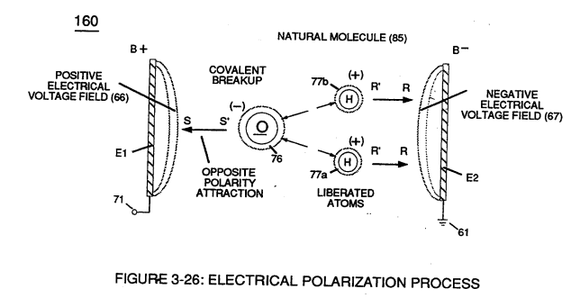](https://stanslegacy.com/uploads/images/gallery/2023-12/FI7iyHF5qFsbEw5X-image-1703376323691.png) | Figure (3-29) [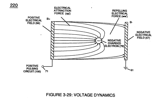](https://stanslegacy.com/uploads/images/gallery/2023-12/5AN8vz6fgBPasqR1-image-1703376333059.png) |
The resultant **electrical force** (qq') between the opposite electrical charged **hydrogen** (77) and **oxygen** (76) atoms keeps **water molecule** (210) intact when the **hydrogen atom** (77) shares its **electron** (84) with **oxygen atom** (76).
> The electrical strength of **attraction force** (qq') between the water molecule atoms is determined by the electrical size of the hydrogen atoms and the displacement of its **negative charged electrons** (84) during covalent sharing. [](https://stanslegacy.com/uploads/images/gallery/2023-12/tgj1TAs4iQMFjqTd-image-1703376101819.png)Oxygen atom becomes **negative electrical charged** (81) since **oxygen atom** (76), now, has a total of ten negative charged **electrons** (79a xxx 79n) in its "K" plus "L" orbits while maintaining it's original **eight positive charged protons** which makes up **oxygen nucleus** (83).Since the **hydrogen proton** (84) (hydrogen nucleus) remains (after covalent link up), then the **hydrogen atom** takes-on a **positive charge** (78) co-equalling the **positive charge** of the **hydrogen nucleus proton** (84).
Together, the total net charge of **water molecule** (85) is zero despite the fact that each water molecule atom retains its electrical charge.
In other words, water molecule (85) is a electrically bipolar molecule having a stable configuration of charged atoms bound together by **electrostatic force** (qq').Electromagnetic bonding forces between unlike **atoms** (76n7) are negligible or non-existence, since **oxygen atom** (76) electrons are paired together, while rotating in opposite direction which, in turn, causes **oxygen atom** (76) to be electromagnetically neutral to **hydrogen atom** (77).
> Electron theory of magnetism requires orbital electrons to spin in the same direction before an atom can exhibit a electromagnetic field.Furthermore, **external electrical force** (66/67) can alter the electromagnetic properties of a atom since electromagnetic force is dependent on the movement of **charged particles** in a electrostatic field **voltage Intensifier circuit** (190) of figure (3-23), now, allows voltage to dissociates **water molecule** (85) by overcoming **electrostatic bonding force** (qq') between **unlike atoms** (76n7) while restricting amp flow, as illustrated in (160) of Figure (3-26).
| Figure (3-23) [](https://stanslegacy.com/uploads/images/gallery/2023-12/7ffVlnHJcIOSoYRS-image-1703232587555.png) | Figure (3-26) [](https://stanslegacy.com/uploads/images/gallery/2023-12/FI7iyHF5qFsbEw5X-image-1703376323691.png) |
| Figure (3-29) [](https://stanslegacy.com/uploads/images/gallery/2023-12/5AN8vz6fgBPasqR1-image-1703376333059.png) | Figure (3-26) [](https://stanslegacy.com/uploads/images/gallery/2023-12/FI7iyHF5qFsbEw5X-image-1703376323691.png) |
| Figure (3-27) [](https://stanslegacy.com/uploads/images/gallery/2023-12/tgj1TAs4iQMFjqTd-image-1703376101819.png) | Figure (3-23) [](https://stanslegacy.com/uploads/images/gallery/2023-12/7ffVlnHJcIOSoYRS-image-1703232587555.png) |
Stationary "**positive**" electrical **voltage-field** (66) (*voltage plate E1*) not only attracts **negative charged oxygen atom** (76) but also pulls away **negative charged covalent electrons** (84) from **water molecule** (210).
[](https://stanslegacy.com/uploads/images/gallery/2023-12/FI7iyHF5qFsbEw5X-image-1703376323691.png)At the same time stationary "**negative**" **electrical voltage field** (67) (*voltage plate E2*) attracts **positive charged hydrogen atoms** (77a/b).Once **negative electrically charged oxygen atom** (76) is dislodged from **water molecule** (85), **covalent bonding** (*sharing electrons between atoms*) ceases to exist, switching-off and disrupting **electrical attraction force** (qq') between unlike atoms (76/77), as further illustrated in (160) of Figure (3-26).
**[](https://stanslegacy.com/uploads/images/gallery/2023-12/tgj1TAs4iQMFjqTd-image-1703376101819.png)Opposite polarity electrical attraction force** (SS') continues to cause **negative charged oxygen atom** (76) to migrate to **positive voltage-plate** (E1) (*positive voltage zone 66*); while, at the same time, **opposite polarity electrical attraction force** (RR') causes **positive charged hydrogen atoms** (77a/b) to migrate in the opposite direction to negative **voltage-plate** (E2) (*negative voltage zone 67*) as **step-charging voltage-wave** (65) increases in voltage amplitude from several millivolts to several hundred volts **during each pulse train** (65a xxx 65n) which, in application, causes **water molecule** (210) of Figure (3-27) charged atoms (76/77) to elongate (increasing distance between unlike atoms 76/77) to the point where **covalent hydrogen electrons** (84) of Figure (3-27) breaks away from **electrostatic force** (qq').Repetitive duplication of **voltage pulse** (65a xxx 65n) continues to separate or split apart other **water molecules** (85a xxx 85n) which, in turns, forms **hydrogen** (86) and **oxygen** (87) **gas-mixture** (88) of Figure (3-24).
Dissociation of **water molecule** (85) by way of **voltage stimulation** (65) is herein called "**The Electrical Polarization Process**", as illustrated in (160) of Figure (3-26).
| Figure (3-24) [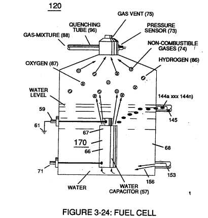](https://stanslegacy.com/uploads/images/gallery/2023-12/eS2UmsVf6o8YkE39-image-1703377231066.png) | Figure (3-26) [](https://stanslegacy.com/uploads/images/gallery/2023-12/FI7iyHF5qFsbEw5X-image-1703376323691.png) |
| Figure (3-30) [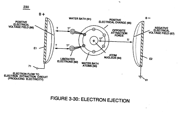](https://stanslegacy.com/uploads/images/gallery/2023-12/kRDULfVghXgQ3Mcm-image-1703377782828.png) | Figure (3-25) [](https://stanslegacy.com/uploads/images/gallery/2023-12/jmc1Z2WkjHNbWiZ6-image-1703201429384.png) |
Applied **electrical attraction force** (TT') and (UU') always being of **equal voltage intensity** but **opposite in electrical polarity** as **voltage amplitude** (65) is attenuated.
Replication of **higher voltage forces** (TT') and (UU') during pulsing operations causes a continued release of other **electrons** (92a xxx 92n) from other **water bath atoms** (93a xxx 93n) which, in practice, increases electrical charges of **water bath** (91) since **water bath** (91) is a dielectric liquid.
**[](https://stanslegacy.com/uploads/images/gallery/2023-12/jmc1Z2WkjHNbWiZ6-image-1703201429384.png)Water bath atoms** (93a xxx 93n) having missing **electrons** (92) take-on a **positive electrical charge** (95) which is subject to and moved by **negative electrical force** (UU'); whereby, the liberated and free floating **negative charge electrons** (92) are subject to and moved by **positive electrical force** (TT'). Applied together, **electrical forces** (TT') and (UU'), now, causes these moving electrically charged particles to superimpose a **physical impact** unto **electrical polarization process** (160), as shown in (170) of Figure (3-25)... thereby, increasing **gas-yield** (88) still further.
[](https://stanslegacy.com/uploads/images/gallery/2023-12/7ffVlnHJcIOSoYRS-image-1703232587555.png)By attenuating **voltage amplitude** (Vo xxx Yn) in conjunction with **pulse-width** (65a xxx 65n) allows **voltage intensifier circuit** (190) of Figure (3-23) to tune-in and match the resonant characteristics or resonant frequency of **water bath** (91) since **water bath** (91) always maintains its dielectric properties during pulsing operations.At resonance, **electrical polarization process** (160) interacts uniformly with liberated **charged particles** (92/95) of Figure (3-25) to obtain a even **higher gas-yield** (88) at **maximum voltage deflection** (xxx Vn).
[](https://stanslegacy.com/uploads/images/gallery/2023-12/jmc1Z2WkjHNbWiZ6-image-1703201429384.png)The **established resonant frequency** is most generally in the audio range from 1 kHz up to and beyond 10 kHz; and is dependent upon the amount of contaminants in **natural water**. Oscillating and superimposing **electrically charged particles** unto the **Electrical Polarization process** at a given pulse-frequency is, now, herein called "**Resonant Action**", as illustrated in (240) of Figure (3-25). To reach **maximum** **gas-yield** (88) **resonant cavity** (170) of Figure (3-25) is shaped into a **tubular structure** (typically 0.50 inch diameter tube inserted into 0.75 inch diameter tube having a .0625 concentric air-gap 3 inches long) which functions as a longitudinal wave-guide to enhance particle movement in a lateral or angular displacement to applied voltage fields (66/67). **Insulated housing** (72) prevents **voltage coupling to water bath** (68) which allows **applied voltage amplitude** (xxx Vn) to remain constant across **water molecules** (85a xxx 85n)... stabilizing gas production during voltage stimulation (65), as shown in (120) of Figure (3-24).
[](https://stanslegacy.com/uploads/images/gallery/2023-12/eS2UmsVf6o8YkE39-image-1703377231066.png)To further prevent voltage fluctuation during resonant action, **Phase Lock Loop** technique of **Pulse Indicator circuit** (110) is utilized during pulsing operations.
The resultant **fuel-gas** (88) is, now, transferred through **Quenching Tube** (96) of Figure (3-41) to, through and beyond **Fuel Injectors** (36) of Figure (3-1) for Hydrogen gas utilization. [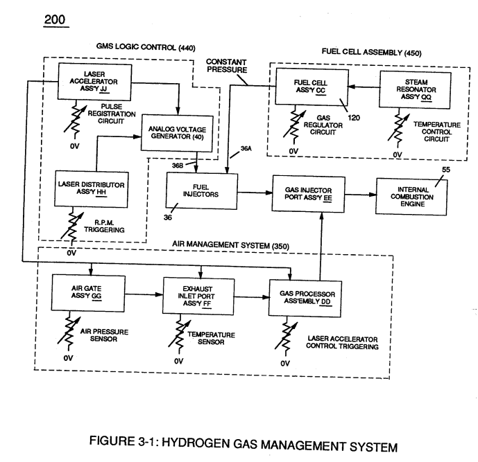](https://stanslegacy.com/uploads/images/gallery/2023-12/oLcI6QctvGXUJUGz-image-1703378297056.png)In cases where applied voltage amplitude is to remain constant while promoting **Resonant Action** during control-state, **incoming pulse train** (64a xxx 64n) is varied independent of voltage amplitude to attenuate **voltage intensity** (66/67) which, in turn, effects gas production.In other applications, **Voltage amplitude** (66/67) in direct relationship to **pulse-train** (64a xxx 64n) may be varied together in a progressive manner to further control gas production. Or pulse-train (64a xxx 64n) can remain constant while voltage amplitude is varied.
In all cases, **Resonant Action** is being promoted to produce hydrogen gas on demand.
In terms of Longevity, **voltage zones** (E1/E2) are composed of or made of stainless steel T304 material which is chemically inert to hydrogen, oxygen, and ambient air gases (*dissolved gases in water*) being liberated from **water bath** (68) during **voltage stimulation** (65). > Under actual certified laboratory testing stainless steel T304 life expectancy (*material decomposition*) is .0001 per year since **voltage** (65) is a physical force, setting up a non-chemical environment since amps consumption is being restricted to a minimum and "no" electrolyte is added to **water bath** (68).In practice, **stainless steel voltage plates** (E1/E2) physically forms **voltage zones** (66/67) regardless of geometric shape or configuration of **resonant cavity** (170).
Under normal gas ignition or gas combustion process, released **Fuel-Gases** (88) of Figure (3-39) as to Figure (3-24) nets a **thermal explosive energy yield** (gtnt) of approximately 2 1/2 rimes greater than gasoline.| Figure (3-39) [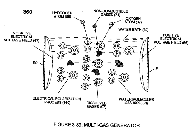](https://stanslegacy.com/uploads/images/gallery/2023-12/DapPTPnafhxr0u3b-image-1703378524117.png) | Figure (3-24) [](https://stanslegacy.com/uploads/images/gallery/2023-12/eS2UmsVf6o8YkE39-image-1703377231066.png) |
| **Dissolved air gases** (97) of Figure (3-39) [](https://stanslegacy.com/uploads/images/gallery/2023-12/DapPTPnafhxr0u3b-image-1703378524117.png) | **Electrical Polarization Process** (160) of Figure (3-26) [](https://stanslegacy.com/uploads/images/gallery/2023-12/FI7iyHF5qFsbEw5X-image-1703376323691.png) |
| **Fuel-Gas mixture** (88) of Figure (3-24) [](https://stanslegacy.com/uploads/images/gallery/2023-12/eS2UmsVf6o8YkE39-image-1703377231066.png) | (330) of Figure (3-37) [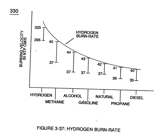](https://stanslegacy.com/uploads/images/gallery/2023-12/WlQY61kCMBoWAmvg-image-1703378872882.png) |
| (320) of Figure (3-36) [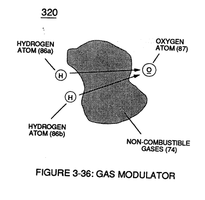](https://stanslegacy.com/uploads/images/gallery/2023-12/rtVP70fKKJltrRpY-image-1703269420703.png) | Figure (3-39) [](https://stanslegacy.com/uploads/images/gallery/2023-12/DapPTPnafhxr0u3b-image-1703378524117.png) |
| (340) of Figure (3-38) [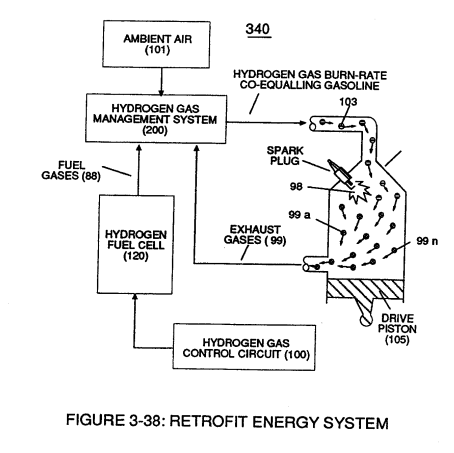](https://stanslegacy.com/uploads/images/gallery/2023-12/MeLbNiqN8Ishsstr-image-1703379003610.png) | Figure (3-24) [](https://stanslegacy.com/uploads/images/gallery/2023-12/eS2UmsVf6o8YkE39-image-1703377231066.png) |
**Water bath** (68) of Figure (3-39) as to Figure (3-24), now, becomes and functions as a "**Gas Mixing Regulator**" since the highest possible **thermal explosive energy yield** (gtnt) obtainable from hydrogen during "normal" **gas ignition** (98) is the exact composition of water where **two hydrogen atoms** (86a / 86b) unite with **oxygen atom** (87).
[](https://stanslegacy.com/uploads/images/gallery/2023-12/FI7iyHF5qFsbEw5X-image-1703376323691.png)Inherently, the utilization of the **Electrical Polarization Process** (160) of Figure (3-26) in conjunction with the use of chemically inert stainless steel (T304 material) **voltage zones** (E1 / E2) submerged in **natural water** (68) sustains and maintains **gas mixing ratio** (88) by simply preventing the consumption of both the **hydrogen** (86) and **oxygen** (87) gases by way of not encouraging "electrical heat" or "chemical interaction" associated with amp consumption.Remember, **Electrical Polarization Process** (160) is a physical process which uses **opposite electrical polarity attraction force** (qq') to perform work by disrupting and switching off the covalent bond between the unlike charged water molecule atoms.
To further reduce **hydrogen burn-rate** (330) of Figure (3-37) to other fossil-fuel burning levels, additional **non-combustible gases** (99a xxx 99n) (*supplied via ambient air 101*) is added to **gas-mixture** (88) by way of **gas ignition process** (98) occurring inside **internal combustion engine** (55) **piston cylinder** (102), as illustrated in (340) of Figure (3-38).
| **hydrogen burn-rate** (330) of Figure (3-37) [](https://stanslegacy.com/uploads/images/gallery/2023-12/WlQY61kCMBoWAmvg-image-1703378872882.png) | (340) of Figure (3-38) [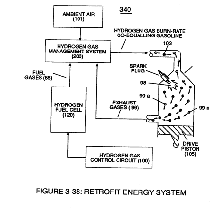](https://stanslegacy.com/uploads/images/gallery/2023-12/hCQI9T9DxApWIQWc-image-1703231476158.png) |
... releasing **thermal explosive energy** (gtnt) which, in turns, causes piston-action to expel the newly formed **non-combustible exhaust gases** (99) for recycling.
The liberated and cooled **exhaust gases** (99) is, now, directed to **hydrogen injector system** (200) which systematically meter-mixes and superimposes a predetermined amount of **non-burnable gases** (99) of Figure (3-38) onto incoming **ambient air gases** (101) which is being directed to **engine cylinder** (102) to sustain and maintain both the "**Gas Modulator Process**" (320) of Figure (3-36) and the "**Gas Ignition Process**" (98), simultaneously.
| "**Gas Modulator Process**" (320) of Figure (3-36) [](https://stanslegacy.com/uploads/images/gallery/2023-12/rtVP70fKKJltrRpY-image-1703269420703.png) | (340) of Figure (3-38) [](https://stanslegacy.com/uploads/images/gallery/2023-12/hCQI9T9DxApWIQWc-image-1703231476158.png) |
In essence, then, **ambient air gases** (101) becomes an endless supply of **non-combustible gases** (99A xxx 99n) during the gas ignition process.
The resultant and on-going **Gas Modulator Process** (320) of Figure (3-36), now, allows **hydrogen fuel cell** (120) of Figure (3-24) to be retrofitted to any conventional **internal combustion engine** (55) of Figure (3-1) without engine change by simply metering the proper amount of **exhaust gases** (99a xxx 99n) to comply with and co-equaling any type or different fossil-fuel burning levels, as further illustrated in (330) of Figure (3-37).| **Fuel-Gas mixture** (88) of Figure (3-24) [](https://stanslegacy.com/uploads/images/gallery/2023-12/eS2UmsVf6o8YkE39-image-1703377231066.png) | (330) of Figure (3-37) [](https://stanslegacy.com/uploads/images/gallery/2023-12/WlQY61kCMBoWAmvg-image-1703378872882.png) |
In terms of operability and performance, **gas modulator** **process** (320) continues to allow a conventional **internal combustion engine** (55) to run on ambient air gases; while, **fuel-gas** (88) not only cuts back and reduces oxygen extraction form ambient air (101) but produces a environmentally safe exhaust gases since **non-combustible gases** (99/74) from both **ambient air gases** (101) and **Fuel-Gas** (88) are thermally inert to **gas ignition process** (98).
# Gas Processor To obtain higher energy-yields beyond the normal gas combustion process, **ionized ambient air gases** (104) of Figure (3-31) is, now, exposed to and intermixed with **Fuel-Gases** (88) prior to **thermal gas ignition** (98) of Figure (3-38), as illustrated in (240) of Figure (3-31).| Figure (3-31)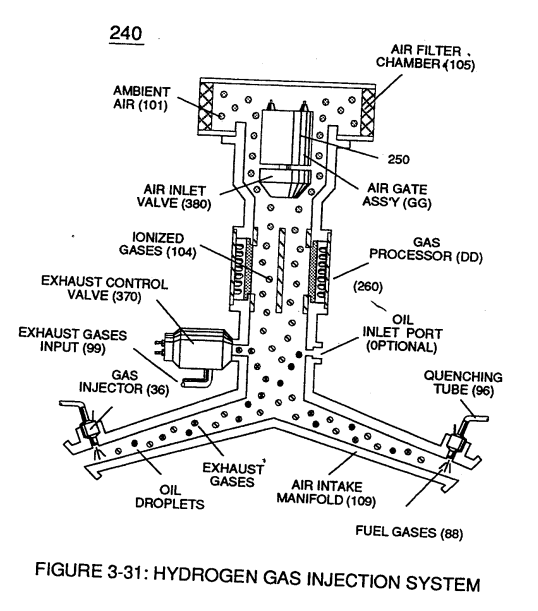 | Figure (3-38) [](https://stanslegacy.com/uploads/images/gallery/2023-12/hCQI9T9DxApWIQWc-image-1703231476158.png) |
...opposite **electrical attraction forces** (xx') and (yy') being of equal intensity, as further illustrated in (260) of Figure (3-33).
Once electron ejection occurs, the liberated and free floating **electrons** (117a xxx 117n) continue to migrate toward **positive voltage zone** (106); whereas, the newly formed **ionized gas atom** (*having missing electrons*) (104) continues to move onward and through **air intake manifold** (109) of Figure (3-31) to **engine cylinder** (102) of Figure (3-38).
| **air intake manifold** (109) of Figure (3-31) [](https://stanslegacy.com/uploads/images/gallery/2023-12/BEpqogfwYffUI6y9-image-1703268011715.png) | **engine cylinder** (102) of Figure (3-38) [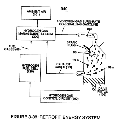](https://stanslegacy.com/uploads/images/gallery/2023-12/yB8tZ6LqeFmcYRcU-image-1703230122079.png) |
| **Electron Extraction Circuit** (270) of Figure (3-34) [](https://stanslegacy.com/uploads/images/gallery/2023-12/bU3ziUnuN8oEc6BH-image-1703379867341.png) | **Voltage Intensifier Circuit** (60) of Figure (3-22) [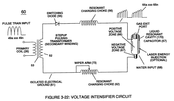](https://stanslegacy.com/uploads/images/gallery/2023-12/ac0BtQ09MXEOZruA-image-1703379886022.png) |
Repetitive formation of electrical voltage force or **voltage intensity** (65a xxx 65n) of Figure (3-21) attracts and causes **liberated electrons** (117a,xxx 117n) to move electrically away from **gas resonant cavity** (410) and physically interact with **light bulb filament** (115) to initiate and perform **kinetic conversion process** (390), as further illustrated in (270) of Figure (3-34).
| **voltage intensity** (65a xxx 65n) of Figure (3-21) [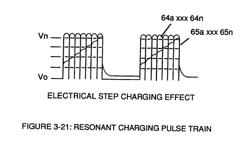](https://stanslegacy.com/uploads/images/gallery/2023-12/2lqF1gDBpLmvgIK1-image-1703379995321.png) | **kinetic conversion process** (390) as to (270) of Figure (3-34) [](https://stanslegacy.com/uploads/images/gallery/2023-12/bU3ziUnuN8oEc6BH-image-1703379867341.png) |
The newly established and on-going **electron conversion process** (390) continues to aid **ionized gas process** (260) as other **gas atoms** (101a xxx 101n) are destabilized into **ionized gas vapor** (104a xxx 104n).
The **electron conversion process** (390) is, of course, terminated when applied pulse **voltage potential** (65) is switched off. Pulsating voltage potential or **voltage intensity** (65a xx 65n) is adjusted, also, to "tune-in" to the resonant properties of **ambient air gases** (101) since **ambient air gases** (101) exhibits a dielectric value (air-gap of one inch resisting electron arc-over of up to 17,000 volts applied) between **voltage plates** (E3) and (E4), forming **capacitor** (410) of Figure (3-34). **Voltage fields** (106/107) are physically configured (*skin effect*) by T304 stainless steel material to form **voltage plates** (E3/E4) of Figure (3-33) which are not only chemically inert to **gas ionization process** (260) but, also, forms tubular **Gas Resonant Cavity** (410) of Figure (3-34) having approximately the same size and shape of **liquid resonant cavity** (170) of Figure (3-25), as illustrated in (270) of Figure (3-34).| **liquid resonant cavity** (170) of Figure (3-25) [](https://stanslegacy.com/uploads/images/gallery/2023-12/jmc1Z2WkjHNbWiZ6-image-1703201429384.png) | (270) of Figure (3-34). [](https://stanslegacy.com/uploads/images/gallery/2023-12/bU3ziUnuN8oEc6BH-image-1703379867341.png) |
| Figure (3-33) 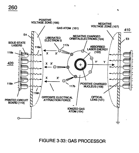 | (270) of Figure (3-34) [](https://stanslegacy.com/uploads/images/gallery/2023-12/bU3ziUnuN8oEc6BH-image-1703379867341.png) |
The absorbed **laser energy** (122) of Figure (3-35) not only causes ionized **gas atom orbital electrons** (124) to be deflected away from **gas atom nucleus** (108) but, also, weakens **electrostatic force** (AA') between **gas atom nucleus** (108) and deflecting **electrons** (123a xxx)
... allowing even a greater number of electrons (117a xxx) to be ejected from ionized gas atom (104) being simultaneously subjected to Electron Extraction Process (260), as illustrated in (280) of Figure (3-35).
[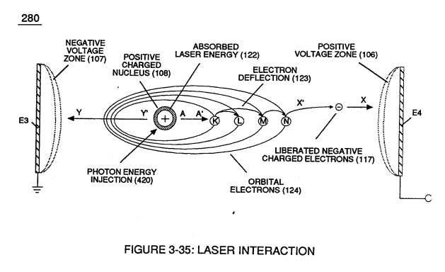](https://stanslegacy.com/uploads/images/gallery/2023-12/jglJdXxetuZ7I3mi-image-1703380690802.png)In essence, then, **laser interaction** (280) along with applied **voltage process** (260) causes **gas atom** (101) to go into sub-critical state (*destabilizing the mass entity of a gas atom) since absorbed laser energy (122) prevents electrons re-capture (atoms accepting electrons*) while **interfacing circuit** (270) dislodges, captures, and immediately consumes **ejected electrons** (117a xxx) In other words, **ambient air gases** (101) has, now, become **electromagnetically primed destabilized gas atoms** (l04a xxx 100n) having missing electrons.
**Solid state light-emitting diode** (118) of Figure (3-33) arranged in a **cluster-array** (118a xxx 118n) mounted on **printed circuit board** (119) emits a discrete wave-length of light energy (*electromagnetic energy*) when **light circuit assembly** (420) of Figure (3-43) is **electrically pulsed** (126a xxx 126n) via **variable pulsing circuit** (125) in such a way as to vary **light intensity** (116) to match the light absorption rate of **ionized gas** (104), and, is determined with respect to the forward current through Led's (118) by (Eq 15) [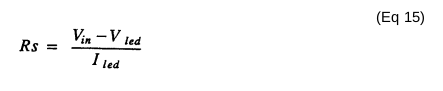](https://stanslegacy.com/uploads/images/gallery/2023-12/bGtrt6OAbopr6IC3-image-1703380798742.png) Where I led, is the specified forward current (typically 20ma per diode); V led is the led voltage drop (typically 1.7 volts for red emitter's).**Ohm's law** for **led circuit** in **parallel array**, and, is given by (Eq 16)
[](https://stanslegacy.com/uploads/images/gallery/2023-12/JVUBKdVH8zzGR1s7-image-1703380895060.png) Where > It is the forward current through led cluster-array; Vcc is volts applied (typically 5 volts) WherebyLaser or light intensity is variable as to duty cycle on/off pulse frequency from 1hz up to and beyond 10khz, and is given by (Eq 17)
> Le is light intensity in watts; Tl is current on-time; 1'2 is current off-time; and (ION) = RMS value of > load current during on-period. [](https://stanslegacy.com/uploads/images/gallery/2023-12/BEpqogfwYffUI6y9-image-1703268011715.png)[](https://stanslegacy.com/uploads/images/gallery/2023-12/lHP94H3qrhSf1jnp-image-1703380915073.png) In terms of assembly, **gas resonant cavity** (410), **electron extraction circuit** (270), **optical lens** (121) forms **gas processor** (260) of Figure (3-31).In retrospect to operational parameters, led's (118) light spectrum (*extending from the visible into the Ultraviolet light region*) can be selected for a given or predetermined **electromagnetically** **gas priming application** (280) since **gas nucleus** (108) is more responsive to coherent rather than diffused light source.
[](https://stanslegacy.com/uploads/images/gallery/2023-12/jglJdXxetuZ7I3mi-image-1703380690802.png)Applied **voltage amplitude** (Va xxx Vn), applied voltage **pulse frequency** (65a xxx 65n), and applied **current pulse train** (126a xxx 126n) are design variable to "tune-in" to the resonant properties of **gas atom** (101) while stimulating and performing **gas process** (260) which attenuates **electrical force** (AA') of Figure (3-35) to disrupt the mass equilibrium of **gas atom** (104).The resultant and newly formed **sub-critical gas atoms** (104a xxx 104n) are directed onward through **air intake manifold** (109) of Figure (3-31) to and beyond both **exhaust gas metering port** (370) and **injector port** (36) where **metered fuel-gas** (88), **metered exhaust gases** (99), and **metered sub-critical gas atoms** (104a xxx 104n) forms **gas-mixture** (103) entering **engine cylinder** (102), as illustrated in (240) of Figure (3-31) as to (340) of Figure (3-38).
| (240) of Figure (3-31) [](https://stanslegacy.com/uploads/images/gallery/2023-12/RZgv6N5lO3RYvQVg-image-1703267421175.png) | (340) of Figure (3-38) [](https://stanslegacy.com/uploads/images/gallery/2023-12/hCQI9T9DxApWIQWc-image-1703231476158.png) |
**Sub-critical Oxygen atom** (129) having less than the normal amount of **covalent electrons** (orbital electrons) is unable to reach "stable-state" (*six to eight covalent electrons required*) when the two **hydrogen atoms** (128 a/b) seek to form the water molecule during thermal gas ignition.
**Absorbed laser energy** (131) of **hydrogen gas atom nucleus** (133) weakens **"electrical bonding" force** (CC') between **hydrogen atom electron** (132) and **hydrogen atom nucleus** (133);
while, at the same time, **absorbed laser energy** (135) prevents **oxygen atom** (129) from reaching "stable state" when **electrical attraction force** (BB') (opposite electrical attraction force being equivalent to the number of missing electrons) locks onto and pulls away **hydrogen atom electron** (132) while **repelling force** (DD') keeps the two **positive charged nucleus's** (133/136) apart.
[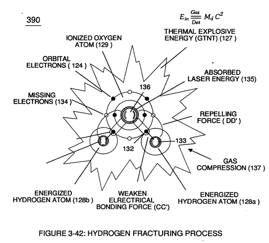](https://stanslegacy.com/uploads/images/gallery/2023-12/kfEIJ9oXKSQGdG0T-image-1703231970050.png)These "'**abnormal**" and "**unstable**" conditions coupled with **thermal interaction** (gas ignition) under **gas compression** (137) of Figure (3-42) as to Figure (3-38) (*fuel-gas 88 being compressed via piston-action 105*) causes **combustible gas atoms** (129 and 128a/b) to decay ... releasing **thermal explosive energy** (gtnt) (127) under control means.This atomic thermal-interaction between sub-critical **combustible gas atoms** (127 and 128a/b) is, now, herein after called "**The Hydrogen fracturing Process**. "
# Laser Distributor [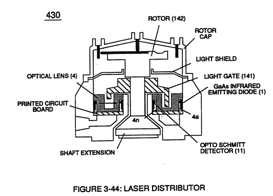](https://stanslegacy.com/uploads/images/gallery/2023-12/fwlFaeAo0Kc4kiVD-image-1703231376468.png)**Laser Distributor assembly** (430) of Figure (3-44) functions in similar manner as **Laser Accelerator** (20) of Figure (3-10) except **light-gate** (141) of Figure (3-44) rotates in the same direction of **Spark-rotor** (142) and being displaced opposite to **rotor blade** (142), allowing intermixed **processed ambient air gases** (101) and **Fuel-Gases** (88) to enter **engine cylinder** (102) of Figure (3-38), as illustrated in **Injector Control Circuit** (300) of Figure (3-4).| **Laser Accelerator** (20) of Figure (3-10) [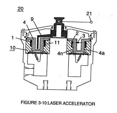](https://stanslegacy.com/uploads/images/gallery/2023-12/HDLNOmyyxVbMa7Qq-image-1703231512088.png) | **engine cylinder** (102) of Figure (3-38) [](https://stanslegacy.com/uploads/images/gallery/2023-12/Q4iFEAzuA1BR3it4-image-1703231477742.png) |
| Figure (3-1) [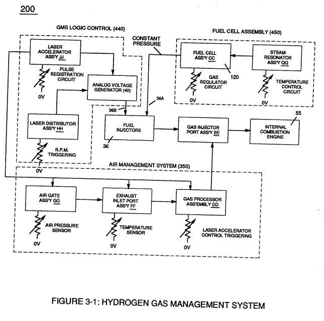](https://stanslegacy.com/uploads/images/gallery/2023-12/63xXWMI18EUm751n-image-1703231251786.png) | Figure (3-4) [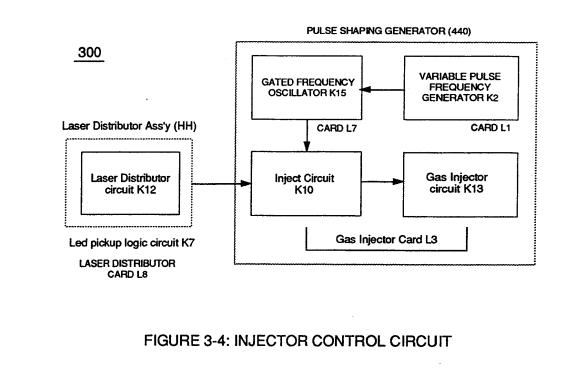](https://stanslegacy.com/uploads/images/gallery/2023-12/whRKNV0TsUvGIS1d-image-1703231300544.png) |
Interlocking **Laser Accelerator output** {JJ) with **Laser Distributor output** (HH) of Figure (3-1) causes **Fuel-Injectors** (36) to be "Tuned" with both **Air Management System** (350) of Figure (3-2) and **Hydrogen Gas Control Circuit** (100) of Figure (3-5) to maintain constant **Fuel-mixing Ratio** (290) of Figure (3-3) during engine performance.
| Figure (3-2) [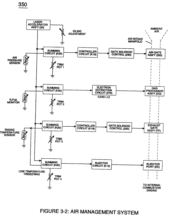](https://stanslegacy.com/uploads/images/gallery/2023-12/XO2etRCiPJqXwH8O-image-1703231274750.png) | Figure (3-5) [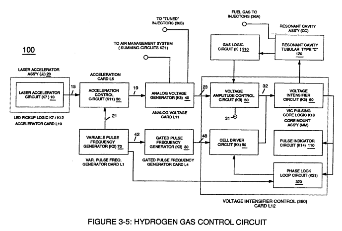](https://stanslegacy.com/uploads/images/gallery/2023-12/6PSO3ExpRKOuqNXU-image-1703231313963.png) |
Opposite or reverse movement of **Laser Accelerator** (JI) decreases **Injectors** (36) **on-time** which, in turns, reduces engine speed.
# Impurity Extraction Process [](https://stanslegacy.com/uploads/images/gallery/2023-12/SfsY9Ms8MRP5eM0o-image-1703197304479.png)Suspended and dissolved **water contaminates** (144a xxx 144n) (*typically 20 ppm to 40 ppm in natural water*) of Figure (3-24) being uniformly released from and superimposed onto remaining **water bath** (68) during **Resonant Action** (170) are directed to and passes through **water inlet line** (145) ... causing liberated, moving, and free-floating **micro-sized contaminates** (144a xxx 144n) to be deposited inside **Electrostatic Filter Assembly** (440) and subsequently exposed to **opposite electrical voltage fields** (148/152), as so illustrated in Figure (3-45). **Negative electrically charged contaminates** (157a xxx 157n) migrates to and entrapped by **positive electrical voltage post** (147); while, simultaneously, **positive electrical charged contaminates** (158a xxx 158n) are attracted to and entrapped by **negative electrical voltage post** (151) ... thereby, extracting **contaminates** (144a xxx 144n) from **water bath** (68) [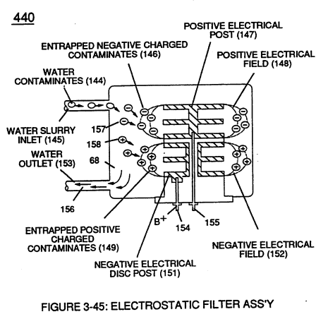](https://stanslegacy.com/uploads/images/gallery/2023-12/J8m3rwK9yPS8xvgK-image-1703230325676.png) ... producing **purified water bath** (156) which is recycled back into **Fuel Cell** (120) of Figure (3-24) since **Resonant Action** (170) also function as and performs as a **water-pump** (Gas rising). Exposing **water contaminates** (144a xxx 144n) to **applied voltage fields** (E1/E2) not only produces **electrical charged contaminates** (157/158); but, also, kills bacteria that might be present in **water bath** (68).Periodically **back-flushing** (rinsing out) is all that is required to ensure and sustain **Electrostatic Filter Process** (440).
# Steam Resonator To further ensure proper **Fuel Cell** optional performance during frigid or below freezing weather conditions, **Steam Resonator** assembly (450) of Figure (3-46) is inserted into **Fuel Cell** (120) of Figure (3-24) and thermostatically activated via **Voltage Intensifier Circuit** (165) which directly applies an **alternate** or **opposite** (166/167) **electrical voltage pulses** *(during amp restriction)* in a sequential manner across **voltage plates** E5/E6.Once positive energized, **water molecule** (210) of **water bath** (68) is deflected toward **voltage surface** (E5) via both **opposite electrical attraction force** (162) and **electrical repelling force** (161).
| Figure (3-46)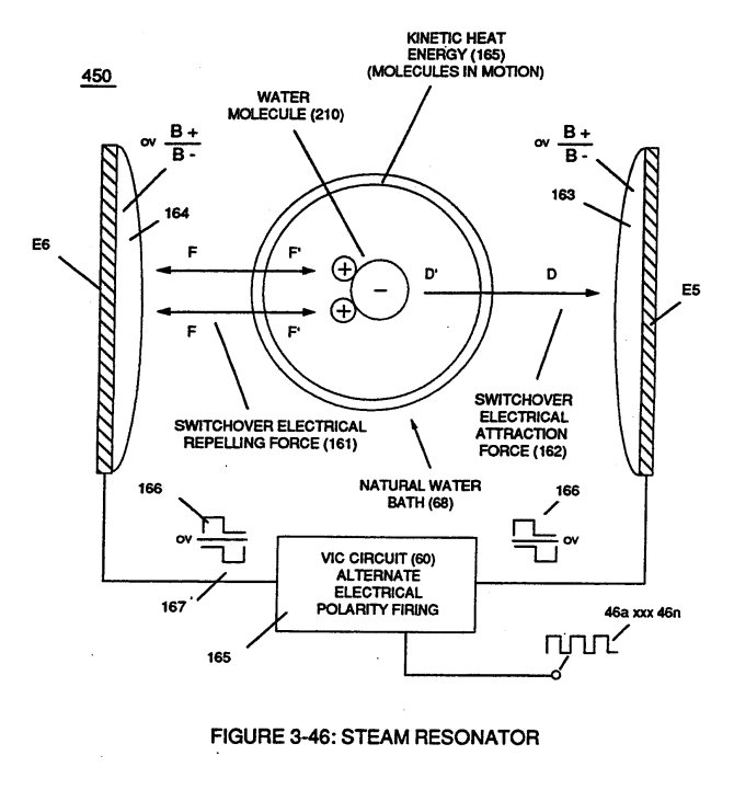 | Figure (3-24) |
... producing **kinetic energy** (165) (*particle impact*) which, in turns, heats **water bath** (68).
Repetitive formation of **opposite voltage pulses** (166/167) at a given pulse-frequency continues to **heat water bath** (68) until a desired temperature is reached.
# Diesel Application By simply adjusting **Fuel-**gases (88) of figure (3-38) **burn-rate** (330) of Figure (3-37) from (43 - 37 cm/s) (Gasoline) to (40 - 35 cm/s) (Diesel) burning levels, now, allows **WFC Hydrogen Gas Management System** to be directly retrofitted to conventional **Diesel Engines** since the newly established modulated **Hydrogen Fuel-mixture** (88 - Diesel) co-equals **spark-ignition ratio** (typically .35 -.39 ) of standard **Diesel-Fuel** (Fossil) under compression.| **Fuel-**gases (88) of figure (3-38) [](https://stanslegacy.com/uploads/images/gallery/2023-12/yB8tZ6LqeFmcYRcU-image-1703230122079.png) | **burn-rate** (330) of Figure (3-37) [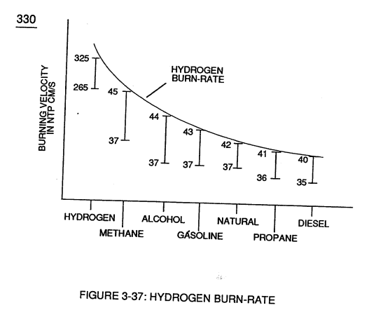](https://stanslegacy.com/uploads/images/gallery/2023-12/CbESYYgb8Xk9jTAc-image-1703230131735.png) |
| Figure (4-11) [](https://stanslegacy.com/uploads/images/gallery/2023-12/pufFIZsDzESvnoJ6-image-1703206086002.png) | Figure (4-14) [](https://stanslegacy.com/uploads/images/gallery/2023-12/7k3oaVVI5k4h3tMX-image-1703206095624.png) |
| **Hydrogen Fuel-Gas Assembly** (450) of Figure (3-1) [](https://stanslegacy.com/uploads/images/gallery/2023-12/bwyleZKqXz2LbuMC-image-1703229950405.png) | **Water Fuel Injector Assembly** (10) of Figure (4-1) [](https://stanslegacy.com/uploads/images/gallery/2023-12/cnI9GgSoTbKZ8DWk-image-1703046505270.png) |
It's design concept and system application complies with the "laws of economics" since micro-chip electronics and plastic mold injection technology help ensure performance reliability and usage
... especially since **Fuel Cell** (120) of Figure (3-24) is miniaturized to **Water Fuel Injector Plug** (40) of Figure (4-2), as further illustrated in [WFC memo 423 DA](https://stanslegacy.com/books/the-birth-of-new-technology/chapter/wfc-423da-water-fuel-injection-system "WFC 423DA - Water Fuel Injection System").| **Fuel Cell** (120) of Figure (3-24) [](https://stanslegacy.com/uploads/images/gallery/2023-12/VC05uhRvsvknmnD8-image-1703229883654.png) | **Water Fuel Injector Plug** (40) of Figure (4-2) [](https://stanslegacy.com/uploads/images/gallery/2023-12/ktSAtfSopo6pX4ES-image-1703229856171.png) |
| [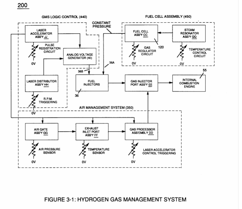](http://stanslegacy.com/uploads/images/gallery/2022-06/87fqMev15vKpDA21-image-1656378349303-05-47.png) | [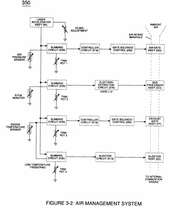](http://stanslegacy.com/uploads/images/gallery/2022-06/qfqKBWQkpTLBpmmK-image-1656378498842-08-16.png) | [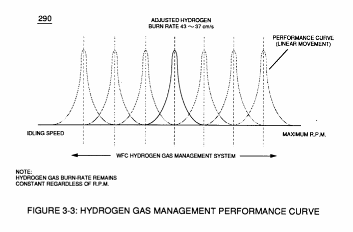](http://stanslegacy.com/uploads/images/gallery/2022-06/Yi4p2cQHeO4zwIrx-image-1656378509671-08-26.png) |
| [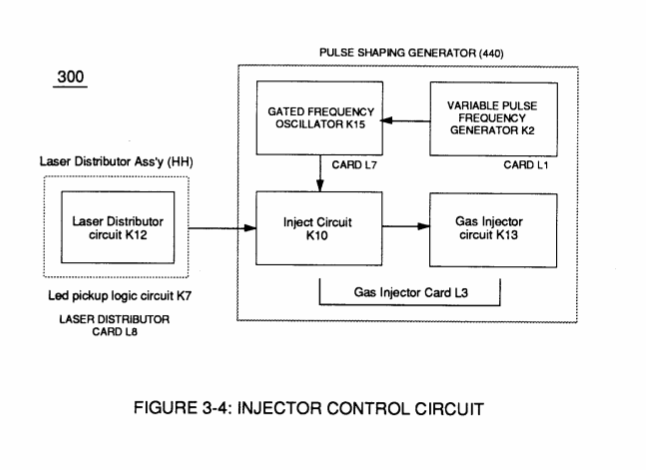](http://stanslegacy.com/uploads/images/gallery/2022-06/wt3G2yMaDSOSlHhh-image-1656378518977-08-36.png) | [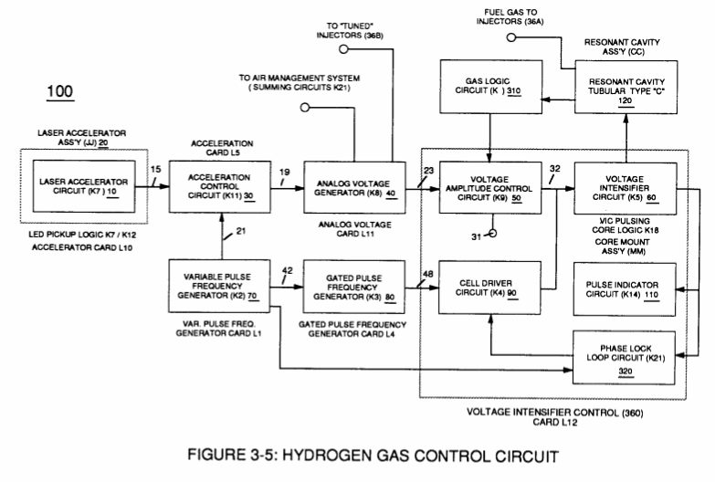](http://stanslegacy.com/uploads/images/gallery/2022-06/ciXweCN1saeyY6Jf-image-1656378530989-08-47.png) | [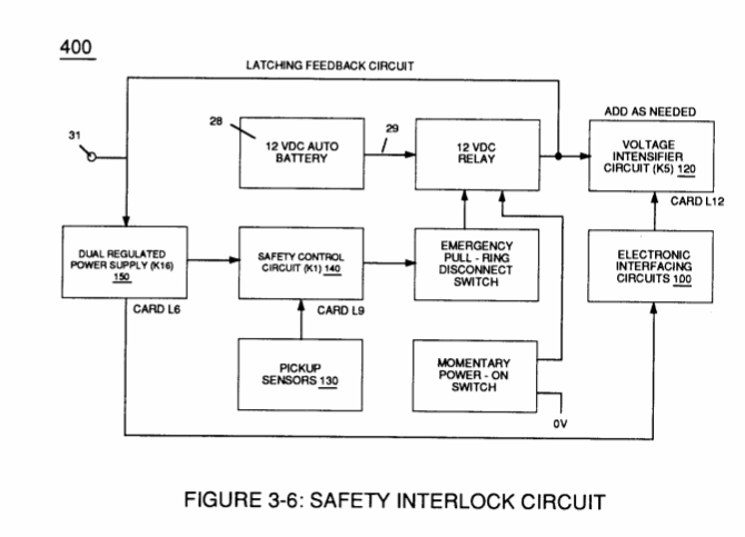](http://stanslegacy.com/uploads/images/gallery/2022-06/7Yh9PGWmrVCafO62-image-1656378542096-08-59.png) |
| [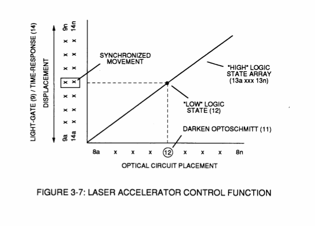](http://stanslegacy.com/uploads/images/gallery/2022-06/5lcNPdzwhdvy87Fi-image-1656378552120-09-08.png) | [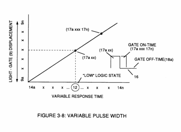](http://stanslegacy.com/uploads/images/gallery/2022-06/3T7FoNgVzyF9dFjB-image-1656378559066-09-16.png) | [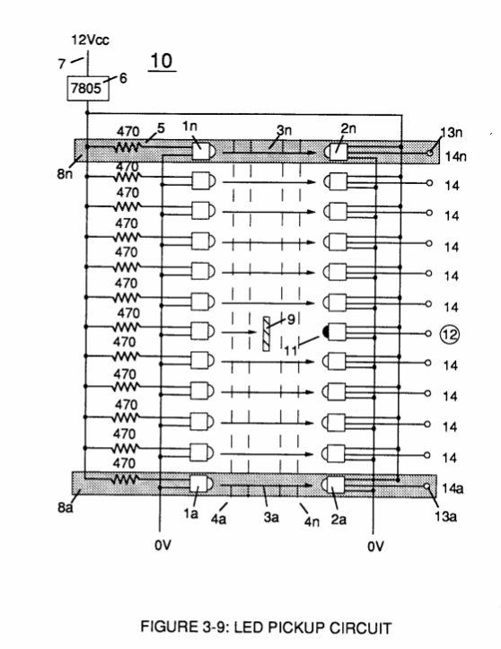](http://stanslegacy.com/uploads/images/gallery/2022-06/fZhMpjE7sz73D5Em-image-1656378566339-09-24.png) |
| [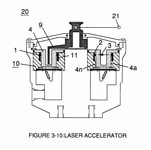](http://stanslegacy.com/uploads/images/gallery/2022-06/VnqfbBE759hYMtOx-image-1656378574809-09-32.png) | [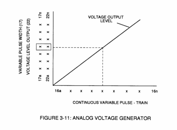](http://stanslegacy.com/uploads/images/gallery/2022-06/81Jkh3kQ8mx0CvB4-image-1656378580364-09-38.png) | [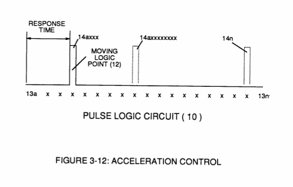](http://stanslegacy.com/uploads/images/gallery/2022-06/xjUcU1BN8HFS8VKT-image-1656378587465-09-45.png) |
| [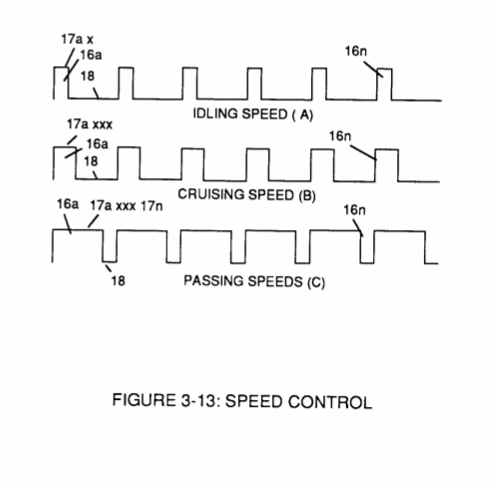](http://stanslegacy.com/uploads/images/gallery/2022-06/bnGzN1OQXnaPIQMU-image-1656378594474-09-52.png) | [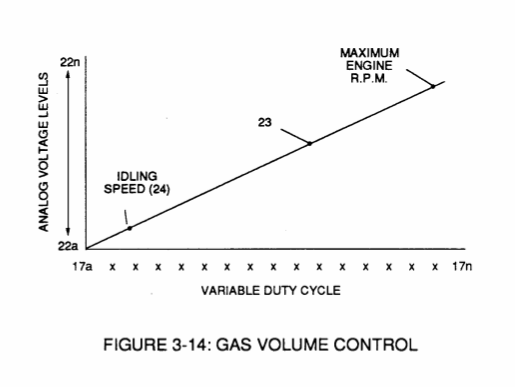](http://stanslegacy.com/uploads/images/gallery/2022-06/5Chkdi1v5hD6SiH3-image-1656378601505-09-59.png) | [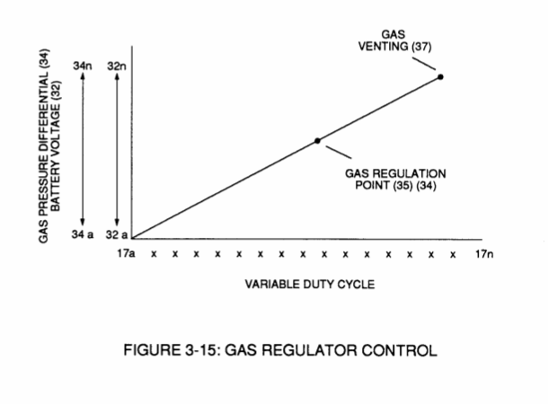](http://stanslegacy.com/uploads/images/gallery/2022-06/w5KAe8p56WdbDqtb-image-1656378606856-10-05.png) |
| [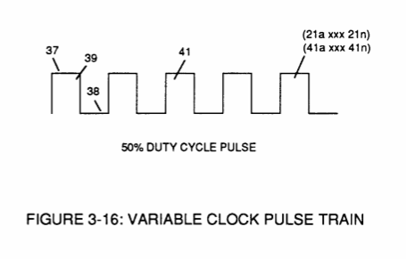](http://stanslegacy.com/uploads/images/gallery/2022-06/9ATAcq0QG8GIMGmE-image-1656378620460-10-18.png) | [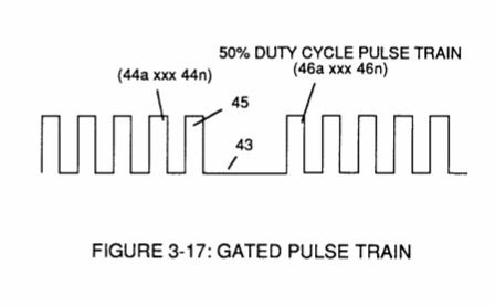](http://stanslegacy.com/uploads/images/gallery/2022-06/rYMCR1NM5GAhVaJh-image-1656378626355-10-24.png) | [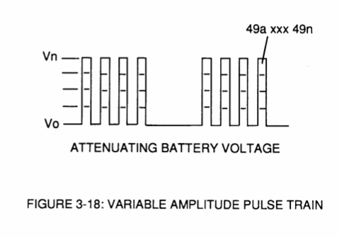](http://stanslegacy.com/uploads/images/gallery/2022-06/cCgAB8tyIHkMSrGS-image-1656378632089-10-30.png) |
| [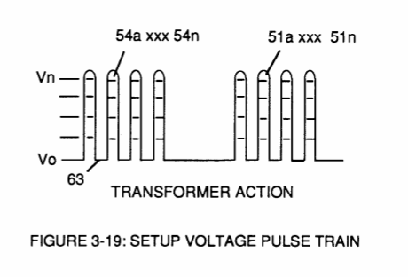](http://stanslegacy.com/uploads/images/gallery/2022-06/tohHqLQZYUyFk3bW-image-1656378640565-10-36.png) | [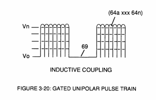](http://stanslegacy.com/uploads/images/gallery/2022-06/H43aHm1mhovBBSEL-image-1656378646994-10-45.png) | [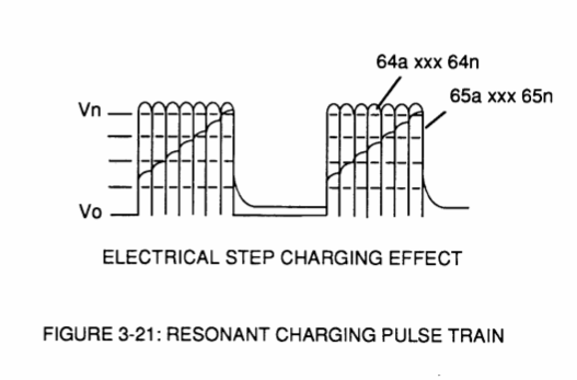](http://stanslegacy.com/uploads/images/gallery/2022-06/a2dCeo6LeefTyPSc-image-1656378654414-10-52.png) |
| [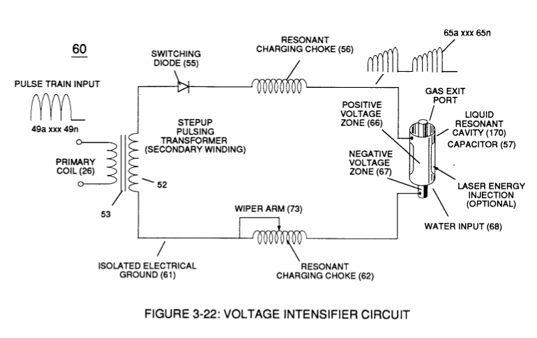](http://stanslegacy.com/uploads/images/gallery/2022-06/Ltiiru0cIDbWw2FP-image-1656378664765-11-01.png) | [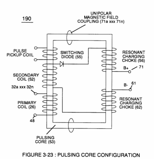](http://stanslegacy.com/uploads/images/gallery/2022-06/U0TD473TnYy7pkMK-image-1656378674398-11-12.png) | [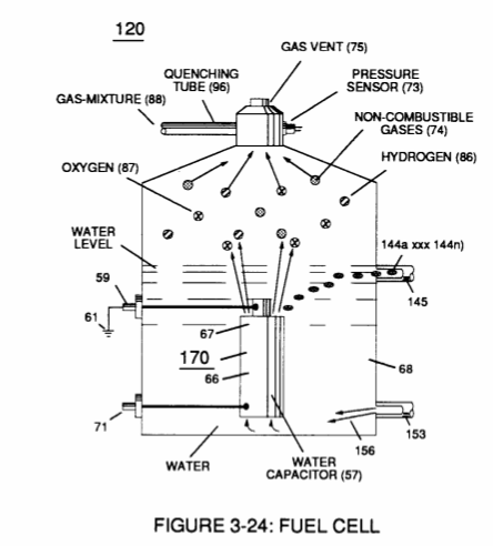](http://stanslegacy.com/uploads/images/gallery/2022-06/JfQPGJZpJNnAck2V-image-1656378682902-11-20.png) |
| [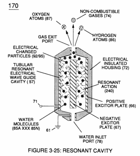](http://stanslegacy.com/uploads/images/gallery/2022-06/VUAOMdsaH8rq0a3z-image-1656378693467-11-31.png) | [](http://stanslegacy.com/uploads/images/gallery/2022-06/5GhIDk6SxBmrzPQA-image-1656378702065-11-40.png) | [](http://stanslegacy.com/uploads/images/gallery/2022-06/0BDacpaJP0lHGWi9-image-1656378712037-11-49.png) |
| [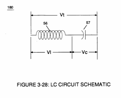](http://stanslegacy.com/uploads/images/gallery/2022-06/YNEi4KG2I1B45y9C-image-1656378719614-11-57.png) | [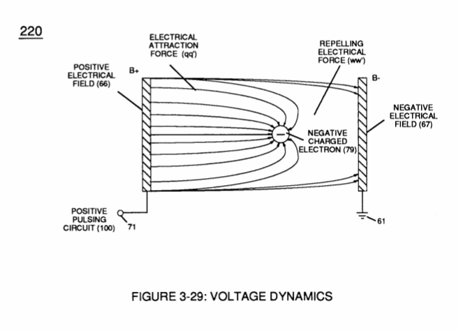](http://stanslegacy.com/uploads/images/gallery/2022-06/fITjZXRRwMwl3PEU-image-1656378725746-12-03.png) | [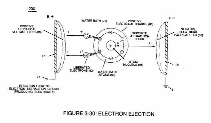](http://stanslegacy.com/uploads/images/gallery/2022-06/CQsgoEqGSUu9rFid-image-1656378734801-12-12.png) |
| [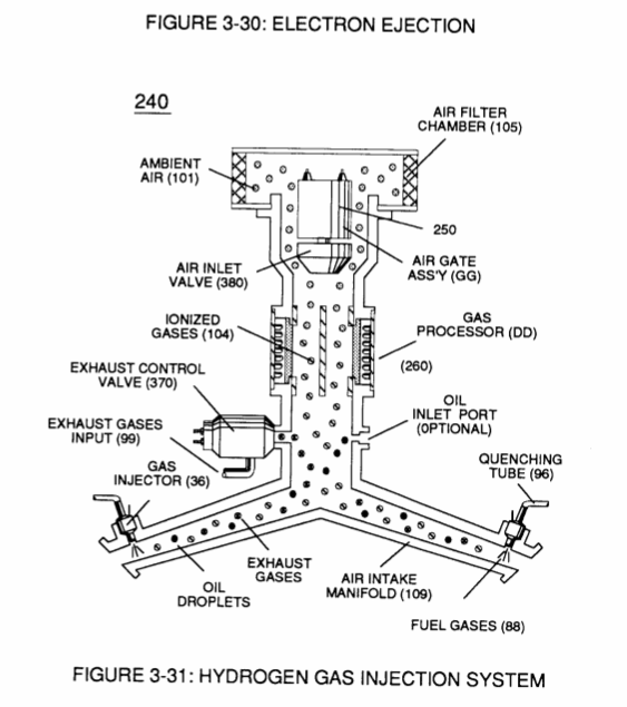](http://stanslegacy.com/uploads/images/gallery/2022-06/OgsL3IVzrGDCFKxg-image-1656378746771-12-23.png) | [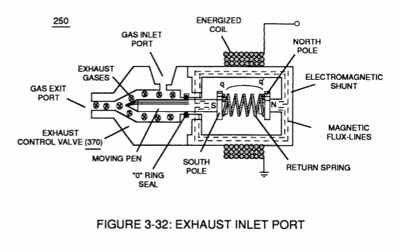](http://stanslegacy.com/uploads/images/gallery/2022-06/pOapCgBQ6IS42lnW-image-1656378762875-12-37.png) | [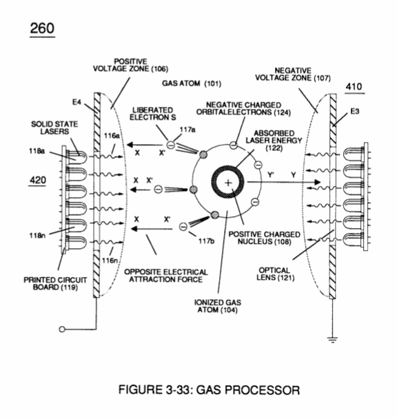](http://stanslegacy.com/uploads/images/gallery/2022-06/o91bCdwmhGK2YkOL-image-1656378770092-12-48.png) |
| [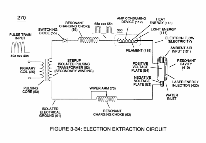](http://stanslegacy.com/uploads/images/gallery/2022-06/9zoOMgB5P4HvxruM-image-1656378777834-12-55.png) | [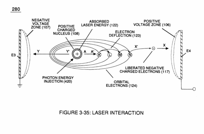](http://stanslegacy.com/uploads/images/gallery/2022-06/hTlQsR03e5wwyfA1-image-1656378783981-13-01.png) | [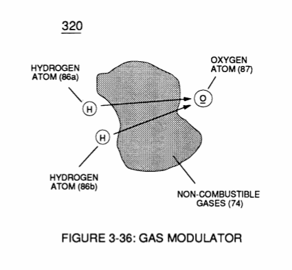](http://stanslegacy.com/uploads/images/gallery/2022-06/R2AZOnPvfeAnMAHM-image-1656378791648-13-09.png) |
| [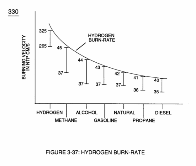](http://stanslegacy.com/uploads/images/gallery/2022-06/Z1cOEDkyfcxyFGzb-image-1656378799212-13-17.png) | [](http://stanslegacy.com/uploads/images/gallery/2022-06/0EfvVS57MIAO0UhF-image-1656378806331-13-24.png) | [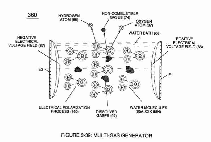](http://stanslegacy.com/uploads/images/gallery/2022-06/KldPakkTfk3bJKy7-image-1656378813558-13-31.png) |
| [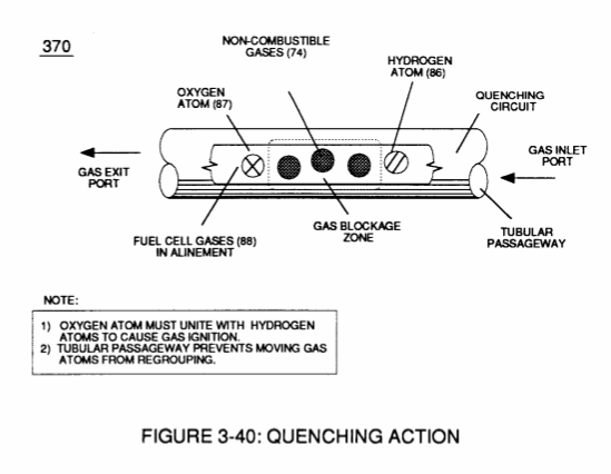](http://stanslegacy.com/uploads/images/gallery/2022-06/p6VKPQAJvBXBeNkc-image-1656378821956-13-39.png) | [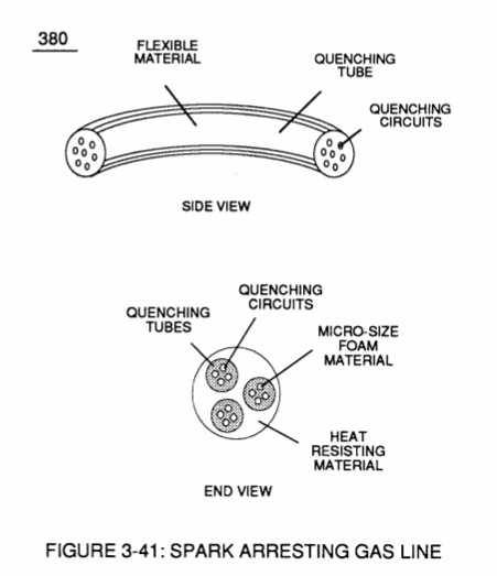](http://stanslegacy.com/uploads/images/gallery/2022-06/4OoMlgp2DEFOUfy7-image-1656378844799-14-02.png) | [](http://stanslegacy.com/uploads/images/gallery/2022-06/OiO3kpEquIGO8UgR-image-1656378852355-14-10.png) |
| [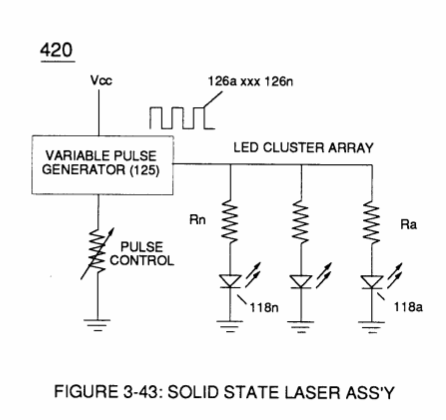](http://stanslegacy.com/uploads/images/gallery/2022-06/yuPcuB9S3c5s4DeA-image-1656378860437-14-18.png) | [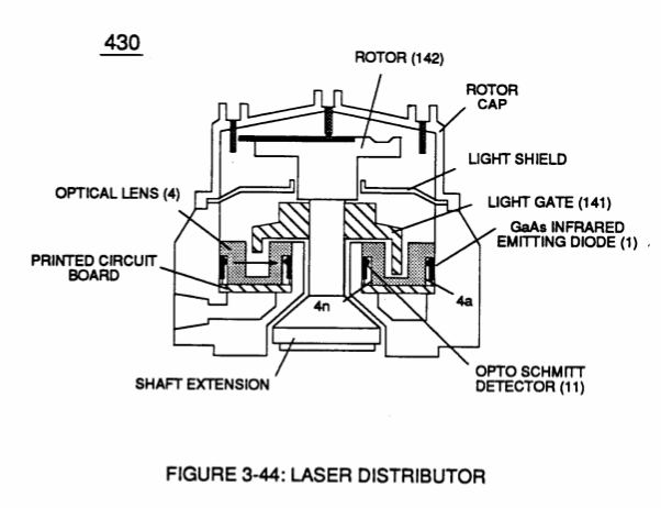](http://stanslegacy.com/uploads/images/gallery/2022-06/UW6HYJ7E6T3LtoXI-image-1656378869427-14-27.png) | [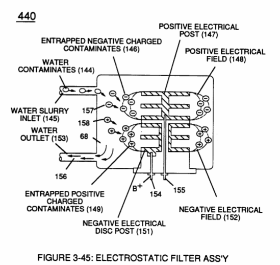](http://stanslegacy.com/uploads/images/gallery/2022-06/qJmeh9p0IgaYIYEn-image-1656378879471-14-37.png) |
| [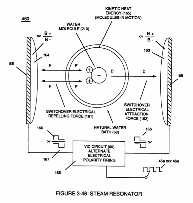](http://stanslegacy.com/uploads/images/gallery/2022-06/dNG7DiuOyjIkBeyo-image-1656378888370-14-46.png) | [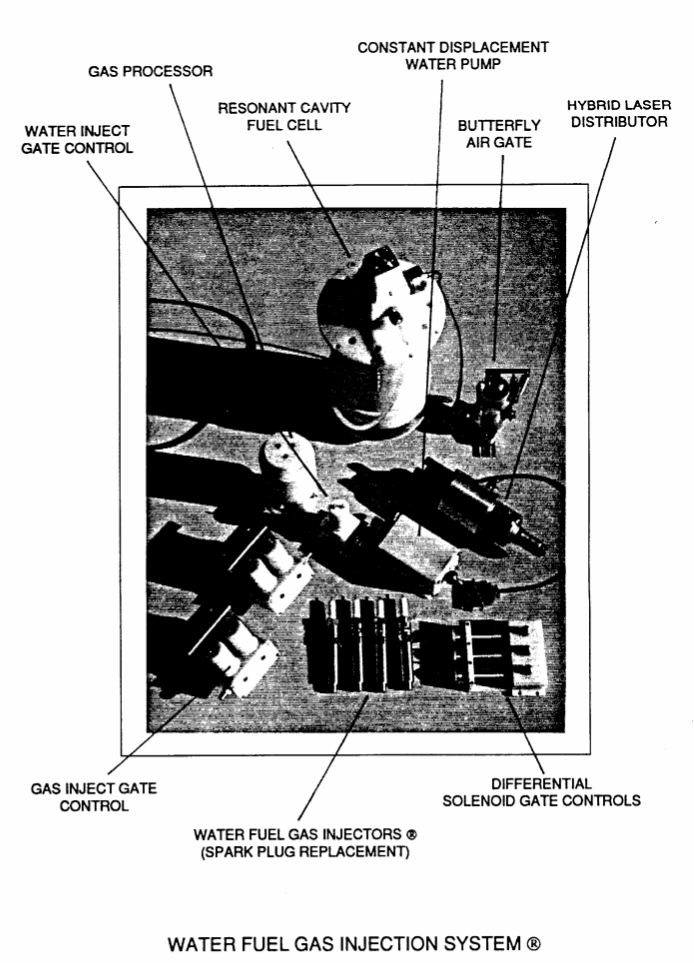](http://stanslegacy.com/uploads/images/gallery/2022-06/gTnbzHSxtVSAHkuI-image-1656378905139-15-02.png) | [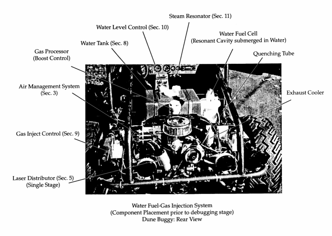](http://stanslegacy.com/uploads/images/gallery/2022-06/d0LXge5C3NpFuMg2-image-1656378924571-15-21.png) |
Reciprocating WFC fuel-kits can be similar to **car design** (340) of Figure (3-38) of WFC ([422 DA](https://stanslegacy.com/books/the-birth-of-new-technology/chapter/wfc-422da-wfc-hydrogen-gas-management-system "WFC 422DA - WFC Hydrogen Gas Management System"));
Whereas, **Water Fuel Injector Kit** (10) of Figure (4-1) can be alternately be used as a self-contained Fuel-unit having no pressurized vessel which converts water directly into thermal explosive energy (gtnt) on demand, as illustrated (10) of Figure (4-1) as to Figure (40) of Figure (4-2).| Figure (4-1) [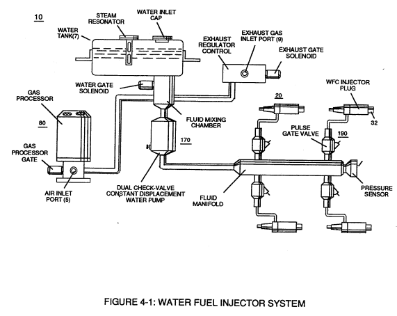](https://stanslegacy.com/uploads/images/gallery/2023-12/YzbA8gTp0KemYjon-image-1703044114002.png) | Figure (4-2) [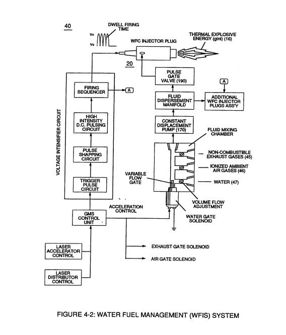](https://stanslegacy.com/uploads/images/gallery/2023-12/GiMddYPcS9B4Olhr-image-1703044123709.png) |
| Figure (4-5) [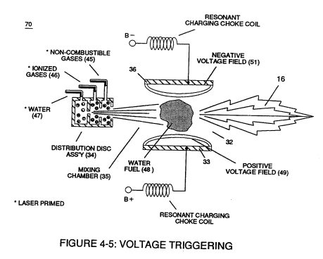](https://stanslegacy.com/uploads/images/gallery/2023-12/uX9zLfvLDlmTuhBw-image-1703044341327.png) | Figure (4-4) [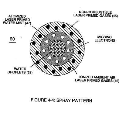](https://stanslegacy.com/uploads/images/gallery/2023-12/1LqEumA5WHe0AOdX-image-1703044350776.png) |
Secondly, **ionized air gases** (46a xxx 46n) of Figure (4-4) (laser primed ambient air gases having missing electrons) produced by **Ambient Air Ionizer** (80) of Figure (4-6) as to Figure (4-1) and **non-combustible gases** (45) of Figure (4-4) are intermixed with **expelling water mist** (47a xxx 47n) to form **Water-fuel** mixture (48) by way of **gas mixing disc** (34) of Figure (4-5) as to (30) of Figure (4-2);
thirdly, the resultant moving **Water-Fuel** mixture (48) of Figure (4-5) enters into **Voltage Igniter Stage** (180) of Figure (4-5) and exposed to high intensity voltage fields (33/36) (*typically 2,000 volts or above @ 10 Khz or above*) of opposite electrical polarity (E7 / E8)
...which, in turn, not only performs electrical polarization process (160) of Figure (3-26) undergoing **Dielectric Resonant** (240) of Figure (3-31);
| (160) of Figure (3-26) [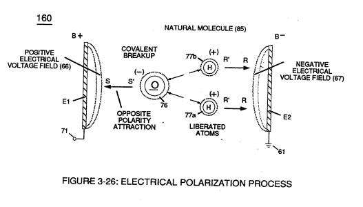](https://stanslegacy.com/uploads/images/gallery/2023-12/6Yg1M4a2A6fzoxzO-image-1703044445938.png) | Figure (3-31) [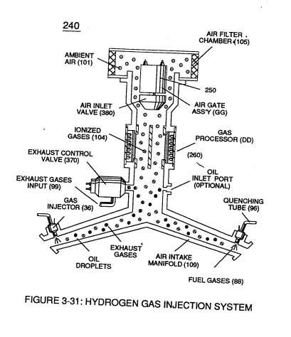](https://stanslegacy.com/uploads/images/gallery/2023-12/gk8uwVm1BF4HsWqC-image-1703044458089.png) |
but, also, sets up and triggers **Hydrogen Fracturing Process** (390) of Figure (3-42) as to Figure (3-6) under control state (on demand) via **electrical-static spark ignition** (49/51) of Figure (4-5)
| **Hydrogen Fracturing Process** (390) of Figure (3-42) [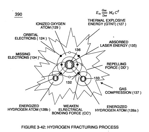](https://stanslegacy.com/uploads/images/gallery/2023-12/agge2fwbI2Y00Pd0-image-1703044479777.png) | Figure (3-6) [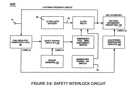](https://stanslegacy.com/uploads/images/gallery/2023-12/ncdiNnxTGEw9Eny8-image-1703044498425.png) |
| Figure (4-5) [](https://stanslegacy.com/uploads/images/gallery/2023-12/uX9zLfvLDlmTuhBw-image-1703044341327.png) |
| Figure (4-2) [](https://stanslegacy.com/uploads/images/gallery/2023-12/GiMddYPcS9B4Olhr-image-1703044123709.png) | Figure (4-1) [](https://stanslegacy.com/uploads/images/gallery/2023-12/YzbA8gTp0KemYjon-image-1703044114002.png) |
To ensure proper energy-flame projection and subsequent energy-flame stability, **constant displacement** **water pump** (170) causes and allows **ionized ambient air gases** (46), **noncombustible gases** (45), and **water** (47) to be displaced under static pressure up to and beyond 125 lbs psi, respectively.
**[](https://stanslegacy.com/uploads/images/gallery/2023-12/uX9zLfvLDlmTuhBw-image-1703044341327.png)Energy-Flame** density is enhanced and sustained by causing **ionized gases** (46a xxx 46n) of **spray port** (42) to be deflected into **liquid spray path** (41), together **water mist** (47) and **ionized air gas** (46) are, now, directed toward and deflected through non-combustible **gas spray path** (43) ... producing uniformed **water-fuel mixture** (48), as illustrated in Figure (4-5). **Energy-Flame** temperature is regulated by controlling the volume flow-rate of each **fluid-mediums** (47 / 45 / 46) in direct relationship to **applied voltage intensity** (33 / 36), as further illustrated in Figure (4-2) as to Figure (4-5).| Figure (4-2) [](https://stanslegacy.com/uploads/images/gallery/2023-12/GiMddYPcS9B4Olhr-image-1703044123709.png) |
| Figure (4-9) [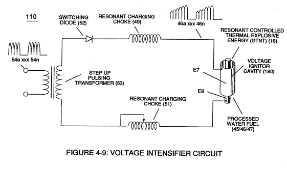](https://stanslegacy.com/uploads/images/gallery/2023-12/5CBewXJPTLhJnono-image-1703045164207.png) | Figure (4-10) [](https://stanslegacy.com/uploads/images/gallery/2023-12/X6GbSuaxjtJ9yQyr-image-1703045172819.png) |
To lower **Energy-flame** temperature simply increase the amount of **non-combustible gases** (45a xxx) or reduced the **fluid flow rate** (45 / 46 / 47) uniformly while lowering **pulse voltage amplitude** (xxx V0).
To establish a predetermined or given **Energy-flame** temperature adjust **fluid-medium** (45 / 46 / 47) and applied **voltage amplitude** (V0 xxx) independent of each other to obtain the desired results. [](https://stanslegacy.com/uploads/images/gallery/2023-12/uX9zLfvLDlmTuhBw-image-1703044341327.png)The resultant **energy-flame** pattern is further maintained by allowing the ignited, compressed, and moving gases (29) of Figure (4-5) to be projected to, pass through and beyond **nozzle-port** (32) under pressure due to gas expansion caused by thermal gas ignition. [](https://stanslegacy.com/uploads/images/gallery/2023-12/X6GbSuaxjtJ9yQyr-image-1703045172819.png) **Voltage Igniter Stage** (180) of Figure (4-5) as to **Voltage Intensifier Circuit** (110) Figure (4-9) as to **Extraction Circuit** (10) of Figure (4-10) performs several functions simultaneously to initiate and trigger thermal explosive energy-yield (gtnt) (16) beyond normal gas burning levels:| Figure (4-9) [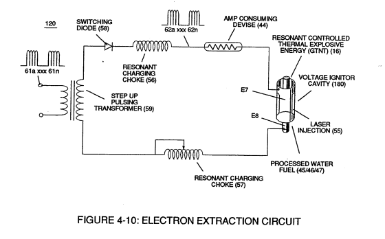](https://stanslegacy.com/uploads/images/gallery/2023-12/OYHUxM9htoFh1dny-image-1703045394258.png) | Figure (4-10) [](https://stanslegacy.com/uploads/images/gallery/2023-12/X6GbSuaxjtJ9yQyr-image-1703045172819.png) |
| Figure (3-26) [](https://stanslegacy.com/uploads/images/gallery/2023-12/6Yg1M4a2A6fzoxzO-image-1703044445938.png) | Figure (3-30) [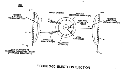](https://stanslegacy.com/uploads/images/gallery/2023-12/CX94TijEdWoZ0T6l-image-1703045508608.png) |
| Figure (4-8) [](https://stanslegacy.com/uploads/images/gallery/2023-12/FigXLeJ7HhT5tTiF-image-1703045558804.png) | Figure (4-10) [](https://stanslegacy.com/uploads/images/gallery/2023-12/OYHUxM9htoFh1dny-image-1703045394258.png) Figure (4-9) [](https://stanslegacy.com/uploads/images/gallery/2023-12/5CBewXJPTLhJnono-image-1703045164207.png) |
| Figure (4-9) [](https://stanslegacy.com/uploads/images/gallery/2023-12/5CBewXJPTLhJnono-image-1703045164207.png) | Figure (4-10) [](https://stanslegacy.com/uploads/images/gallery/2023-12/X6GbSuaxjtJ9yQyr-image-1703045172819.png) |
That, whenever the mass-size of a combustible gas atom is decreased (Md), **thermal explosive energy-yield** (gtnt) is increased (Ein) during thermal gas combustion (Gas // Detonation), as so illustrated in (100) Figure (4-8) as to (90) of Figure (4-7).
| Figure (4-7) [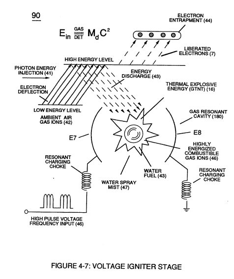](https://stanslegacy.com/uploads/images/gallery/2023-12/KI5axtguzycTCZDB-image-1703045855108.png) | Figure (4-8) [](https://stanslegacy.com/uploads/images/gallery/2023-12/FigXLeJ7HhT5tTiF-image-1703045558804.png) |
| **Ambient Air Ionizer** (**Gas Processor**) (80) of Figure (4-6) [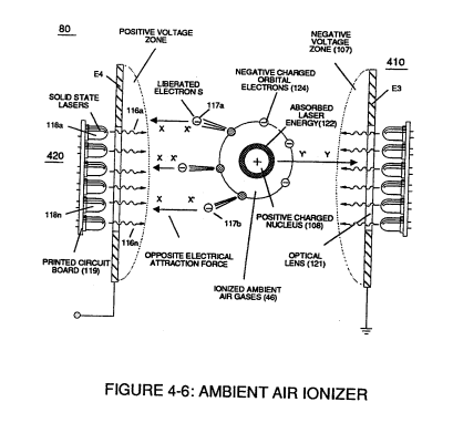](https://stanslegacy.com/uploads/images/gallery/2023-12/LyDup7Y5JJ0s6sp4-image-1703045933733.png) | (10) of Figure (4-1) [](https://stanslegacy.com/uploads/images/gallery/2023-12/YzbA8gTp0KemYjon-image-1703044114002.png) |
| **electron extraction circuit (120) of Figure (4-10)** [](https://stanslegacy.com/uploads/images/gallery/2023-12/OYHUxM9htoFh1dny-image-1703045394258.png) | Figure (4-8) [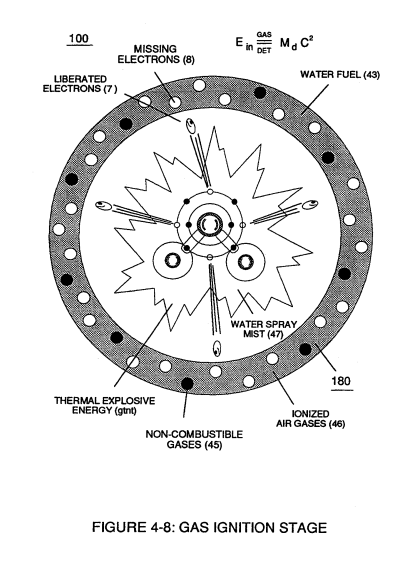](https://stanslegacy.com/uploads/images/gallery/2023-12/sSq6YhYcIoZOdhjy-image-1703045594105.png) |
In other or alternate applications, **laser primed ionized liquid oxygen** (68) of Figure (1-21) ([see WFC memo 420](https://stanslegacy.com/books/the-birth-of-new-technology/chapter/wfc-420-hydrogen-fracturing-process "WFC 420 - Hydrogen Fracturing Process")) and laser primed liquid hydrogen (69) of Figure (1-21) stored in separate fuel-tanks can be used in place of fuel-mixture (48); or, **liquefied ambient air gases** (6) alone with **water-source** (8) can, also, be substituted as a fuel-source (48) to trigger **Hydrogen Fracturing Process** (100).
| **laser primed ionized liquid oxygen** (68) of Figure (1-21) [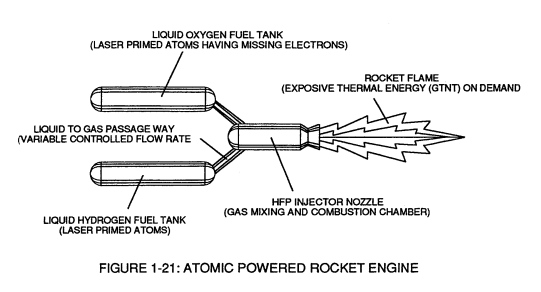](https://stanslegacy.com/uploads/images/gallery/2023-12/hNxy1SmcvLljWTYM-image-1703046125212.png) |
| **WFC Injector Assemblies** (20) of Figure (4-1) [](https://stanslegacy.com/uploads/images/gallery/2023-12/YzbA8gTp0KemYjon-image-1703044114002.png) |
| Figure (4-12) [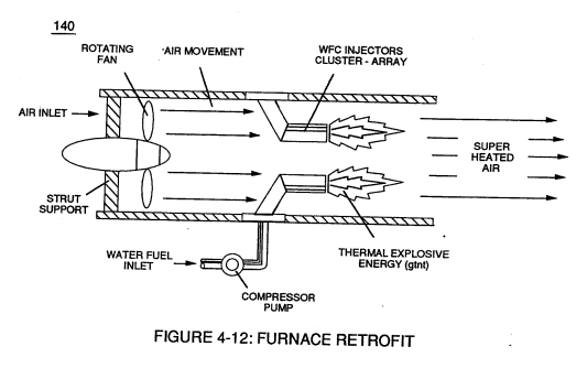](https://stanslegacy.com/uploads/images/gallery/2023-12/1qDP65qVKMv5i9Cl-image-1703046270673.png) | Figure (4-13) [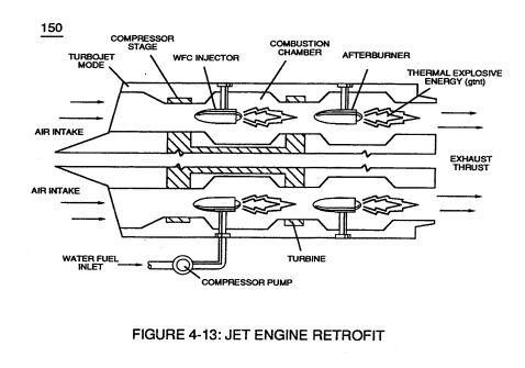](https://stanslegacy.com/uploads/images/gallery/2023-12/e70oucuzLIMa9dbH-image-1703046282227.png) | Figure (4-14) [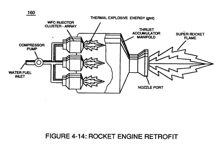](https://stanslegacy.com/uploads/images/gallery/2023-12/ryJBOXenEHgsMgQ6-image-1703046293935.png) |
| [](https://stanslegacy.com/uploads/images/gallery/2023-12/cnI9GgSoTbKZ8DWk-image-1703046505270.png) | [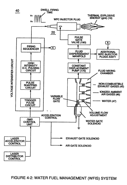](https://stanslegacy.com/uploads/images/gallery/2023-12/6SurEeUSEwiGQWVW-image-1703046416212.png) |
**heating systems** (Figure 4-12), **rockets engines** (Figure 4-14), or even car **spark plugs** (130) of Figure (4-11)
| Figure (4-12) [](https://stanslegacy.com/uploads/images/gallery/2023-12/1qDP65qVKMv5i9Cl-image-1703046270673.png) | Figure (4-13) [](https://stanslegacy.com/uploads/images/gallery/2023-12/e70oucuzLIMa9dbH-image-1703046282227.png) | Figure (4-14) [](https://stanslegacy.com/uploads/images/gallery/2023-12/ryJBOXenEHgsMgQ6-image-1703046293935.png) |
Sequential pulsing of **Water Fuel Injector** (20/30) of Figure (4-1) as to (40) of Figure (4-2) is system activated by **Pulse Gate Valve** (190) of Figure (4-1) to further control a predetermined **energy-flame** (16).
In essence, then, the **Water Fuel Injector** system (40) simply processes and converts water into a useful hydrogen fuel on demand at the point of gas ignition... thereby, **co-equally** or **superseding** fossil-fuel safety standards
... especially when **ionized ambient air gases** (400 xxx 46n) and **non-combustible gases** (45a xxx 45n) are intermixed with **water supply** (47) prior to entering **Water Fuel Injector Plug** (20/30), as illustrated in (40) of Figure (4-2) as to (10) of Figure (4-1).
[](https://stanslegacy.com/uploads/images/gallery/2023-12/cnI9GgSoTbKZ8DWk-image-1703046505270.png) # WFC 423DA-2 - Water Fuel Injection System # Water Fuel Injection System [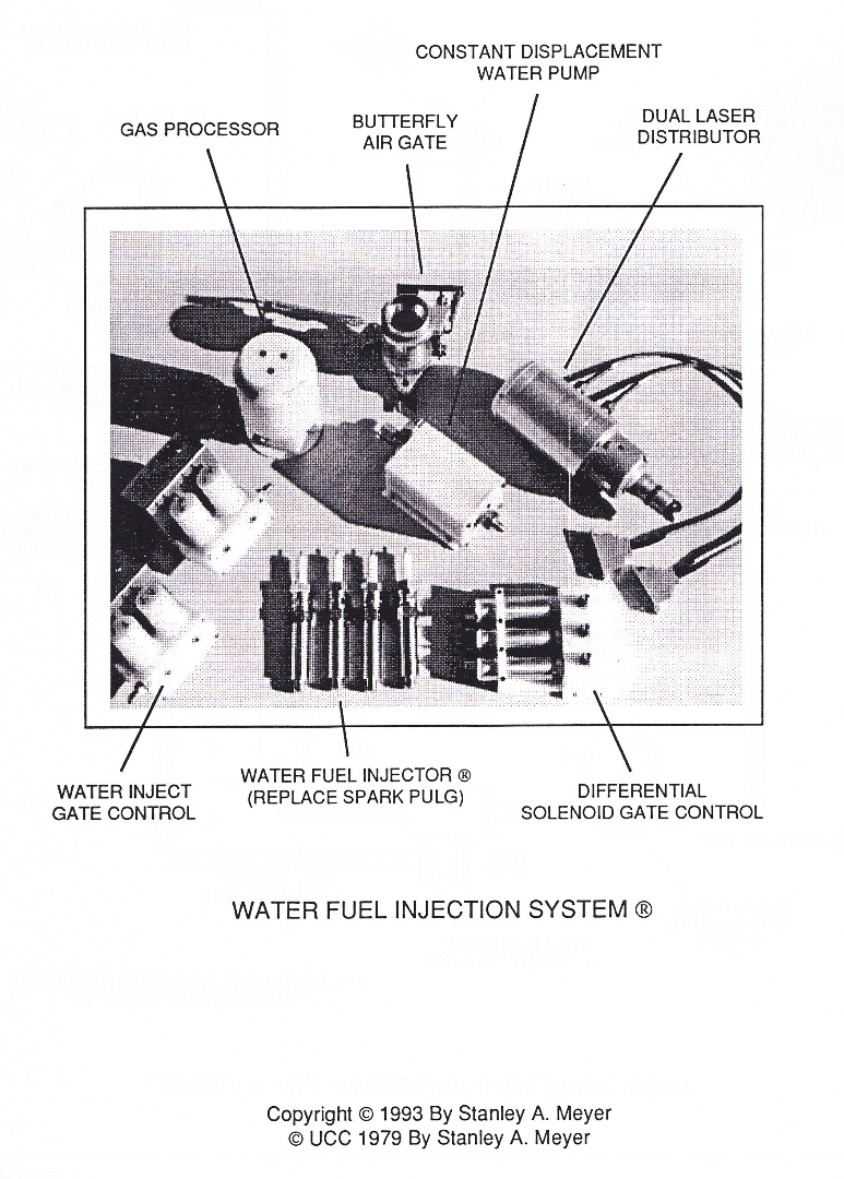](https://stanslegacy.com/uploads/images/gallery/2024-03/8MdQQSgvSerXbNkW-image-1710802161360-49-19.png) ### Water Fuel Injection System WFC Hydrogen Gas Management System is ideally suited as a retrofit energy system to both reciprocating (rotary piston engine) and turbine jet engines associated with the aviation industry...but in different ways: Reciprocating WFC fuel-kits can be similar to car design (340) of Figure (38) of [WFC (422 DA)](https://stanslegacy.com/books/the-birth-of-new-technology/chapter/wfc-422da-wfc-hydrogen-gas-management-system "WFC 422DA - WFC Hydrogen Gas Management System"); Whereas, **Water Fuel Injector Kit** (10) of Figure (1) can alternately be used as a self-contained Fuel-unit having no pressurized vessel which converts water directly into thermal explosive energy (gtnt) on demand, as illustrated (10) of Figure (1) as to Figure (40) of Figure (2B 1-2).| [](https://stanslegacy.com/uploads/images/gallery/2024-03/8zEBCXuDDmHtlhzx-image-1710804322371.png) | [](https://stanslegacy.com/uploads/images/gallery/2024-03/2wTszFLYLqsvlX2S-image-1710818673862-24-31.png) |
Operationally, Water Fuel injector assembly (10) of Figure (1) as to (40) of Figure (2B) performs several functions simultaneously to produce thermal explosive energy-yield (gtnt) (16) on demand:
First water mist (47) of Figure (1-3A) is injected into fuel-mixing chamber (35) of Figure (3B) by way of water spray ports (41a xxx 41n) of Figure (3A); Secondly, **ionized air gases** (46a xxx 46n) of Figure (3A) *(laser primed ambient air gases having missing electrons)* produced by **Ambient Air Ionizer** (80) of Figure (4) as to Figure (1) and **non-combustible gases** (45) of Figure (3A) are intermixed with expelling water mist (47a xxx 47n) to form **Water-fuel mixture** (48) by way of **gas mixing disc** (34) of Figure (3B) as to (30) of Figure (2A); thirdly, the resultant moving **Water-Fuel mixture** (48) of Figure (3B) enters into **Voltage Igniter Stage** (180) of Figure (3B) and exposed to high intensity voltage fields (33 / 36) (typically 2,000 volts or above @ 10 Khz or above) opposite electrical polarity (E7 / E8) ...which, in turn, not only performs electrical polarization process (160) of Figure (25) undergoing **Dielectric Resonant** (240) of Figure (30); but, also sets up and triggers **Hydrogen Fracturing Process** (390) of Figure (41) as to Figure (6) under control state (on demand) via electrical-static spark ignition (49 / 51) of Figure (3B)....releasing thermal explosive energy (gtnt) (16) passing beyond gas exit port (32) of Figure (3B), as further illustrated in Figure (2) as to Figure (1).To ensure proper energy-flame projection and subsequent energy-flame stability, constant placement water pump (170) causes and allows **ionized ambient air gases** (46), **non-combustible gases** (45), and **water** (47) to be displaced under static pressure up to and beyond 125 psi respectively.
**Energy-Flame** density is enhanced and sustained by causing ionized gases (46a xxx 46n) of s**pray port** (42) to be deflected into **liquid spray path** (41), together **water mist** (47) and **ionized air** (46) are, now, directed toward and deflected through non-combustible gas spray path producing uniformed **water-fuel mixture** (48), as illustrated in Figure (3B). **Energy-Flame** temperature is regulated by controlling the volume flow-rate of each fluid mediums (47 / 45/ 46) in direct relationship to applied voltage intensity (33 /36), as further stated in Figure (2B) as to Figure (3B). To elevate **Energy-flame-temperature** still further, help increase **fluid-displacement** (46/47) while maintaining or reducing the volume flow rate of non-combustible gases (45) during an increase of applied voltage amplitude (Vo x Vn) of Figure (32) as to **Voltage Intensifier Circuit** (110) of Figure (7) and **Electron Extraction Circuit** (120) of Figure (8). To lower Energy-flame temperature simply increase the amount of non-combustible gas (45a xxx) or reduced the fluid flow rate (45 / 46/ 47)) uniformly while lowering pulse voltage amplitude (xxx Vo).To establish a predetermined or given Energy-flame temperature adjust fluid-medium (45 / 46 / 47)) and applied voltage amplitude (Vo xxx) independent of each other to obtain the desired results.
The resultant energy-flame pattern is further maintained by allowing the ignited,compressed, and moving gases (29) of Figure (3B) to be projected to, pass through and beyond **nozzle-port** (32) under pressure due to gas expansion caused by thermal gas ignition. **Voltage Igniter Stage** (180) of Figure (3B) as to **Voltage Intensifier Circuit** (110) Figure (7) as to **Extraction Circuit** (120) of Figure (8) performs several functions simultaneously to initiate and trigger thermal explosive energy-yield (gtnt) (16) beyond normal gas burning levels: Water droplets (28a xxx 28n) escaping from spray-mist (47) and exposed to high intensity voltage fields of opposite polarity 33/ 36) are stimulated to undergo Electrical Polarization Process (160) of Figure (25)...which not only separates and splits the unlike atoms of the water molecule but also causes the unlike atoms (hydrogen atoms 77a / 77b and oxygen atom 76) to experience electron ejection (230) of Figure (29) as to (71) of Figure (8) since voltage intensifier circuit (110) of Figure (7) inhibits and prevents electron flow to enter into gas ignition process (180), as further illustrated in Figure (6). The newly liberated water molecule atoms (oxygen 76 and hydrogen atoms 77a / 77b) immediately interact with laser primed ionized ambient air gases (7a xxx In of Figure 1-8) (see [WFC memo 420](https://stanslegacy.com/books/the-birth-of-new-technology/chapter/wfc-420-hydrogen-fracturing-process "WFC 420 - Hydrogen Fracturing Process")) to cause the resultant highly energized and mass destabilized combustible gas atoms (93a xxx 93n) of Figure (8) to perform **Hydrogen Fracturing Process** (80) of Figure (7) when electrostatic force (14/16) thermally ignites (*kinetic agitation*) destabilized water-fuel mixture (93a xxx 93n) under gas compression... preventing the formation of the water molecule during thermal gas ignition....satisfying **Energy Gas Detonation Equation**. [](https://stanslegacy.com/uploads/images/gallery/2024-03/nDzBsuqGP8VkgXQY-image-1710817020257-56-58.png) which states: That, whenever the mass-size of a combustible gas atom is decreased (Md), thermal explosive energy-yield (gtnt) is increased (Ein) during thermal gas combustion (Gas // Detonation.), as so illustrated in (100) Figure (6) as to (90) of Figure (5). [](https://stanslegacy.com/uploads/images/gallery/2024-03/JqeitiAp4qURSnQb-image-1711239500177-18-17.png) Incoming ambient air gases (5a xxx 5n) become laser primed and ionized when passing through Ambient Air Ionizer (Gas Processor) (80) of Figure (4) as to (10) of Figure (1) since **electron extraction circuit** (120) of Figure (8) not only captures and consumes ejected electrons (7a cx 7n) of Figure (6); but, also prevents electron flow into destabilizing gas process (180), as so illustrated in Figure (3B). In terms of performance reliability and safety, ionized air gases (46a xxx 46n) and liquid water (47a xxx 47n) do not become energy activated (volatile) until water-fuel mixture (48) reaches **Voltage Igniter Stage** (180). Injected non-combustible gases (45a xxx 45) retards and controls the combustion rate of the **Hydrogen Fracturing Process** (100) of Figure (6) during gas-ignition. In other or alternate applications, laser primed ionized liquid oxygen (68) of Figure (1-10) CF\* memo 420) and laser primed liquid hydrogen (69) of Figure (1-10) stored in separate fuel tanks can be used in place of fuel-mixture (48); or, liquefied ambient air gases (6) alone with source (8) can, also, be substituted as a fuel-source (48) to trigger Hydrogen Fracturing 10). Additional WFC Injector Assemblies (20) of Figure (2) are arranged in cluster array (20a xxx 20n) to increase energy-yield output (16a xxx 16n) of Figure (10 / 1 / 12). WFC injector assembly (10) of Figure (1) as to (30) of Figure (2A) is design variable to be retrofitable by replacing fossil-fuel injector ports affixed to jet engines (see Figure 11), heating systems (Figure 10), rockets engines (Figure 12), or even car spark plugs (130) of Figure (9) which simply uses **Water Fuel management** (WFMS) system **fluid-metering system** (40) to control gas ignition (16), as illustrated in (40) of Figure (2B).Sequential pulsing of **Water Fuel Injector** (20/30) of Figure (1) as to (40) of Figure (2B) is system activated by **Pulse Gate Valve** (190) of Figure (1) to further control a predetermined **energy-flame** (16).
In essence, then, the **Water Fuel Injector** system (40) simply processes and converts water into a useful hydrogen fuel on demand at the point of gas ignition...thereby, co-equally or superseding fossil-fuel safety standards... especially when ionized **ambient air gases** (46a xxx 46n) and **non-combustible gases** (45a xxx 45n) are intermixed with **water supply** (47) prior to entering. Water Fuel Injector Plug (20 / 30), as illustrated in (40) of Figure (2B) as to (10) of Figure (1). # Voltage Intensifier Coil Assembly [](https://stanslegacy.com/uploads/images/gallery/2024-03/pRn0axjkdpiaDyC0-image-1710802229262-50-27.png) #### 3-1 Coil Wrap Assembly [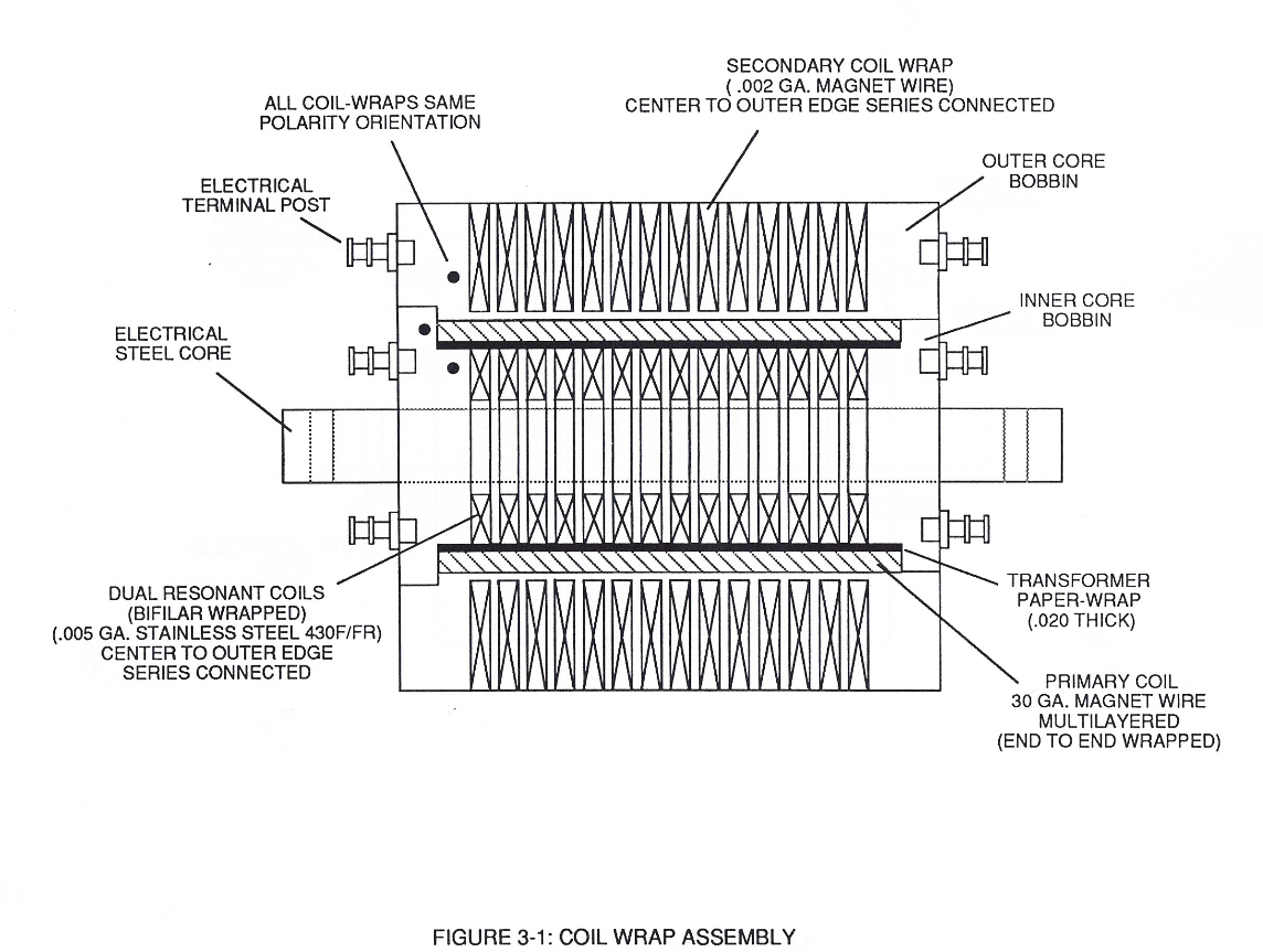](https://stanslegacy.com/uploads/images/gallery/2024-03/CNhbEr80F654Jl6q-image-1711247092269-24-49.png) #### 3-2 (VIC) Coil Assembly [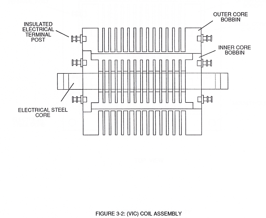](https://stanslegacy.com/uploads/images/gallery/2024-03/0ALjEvukLRwxn6uG-image-1711247119564-25-17.png) #### 3-4 Inner Core Bobbin [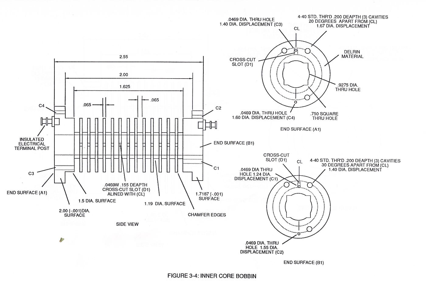](https://stanslegacy.com/uploads/images/gallery/2024-03/48gSOp2ETgsNuQ6v-image-1711247156920-25-54.png) #### 3-5 Outer Core Bobbin [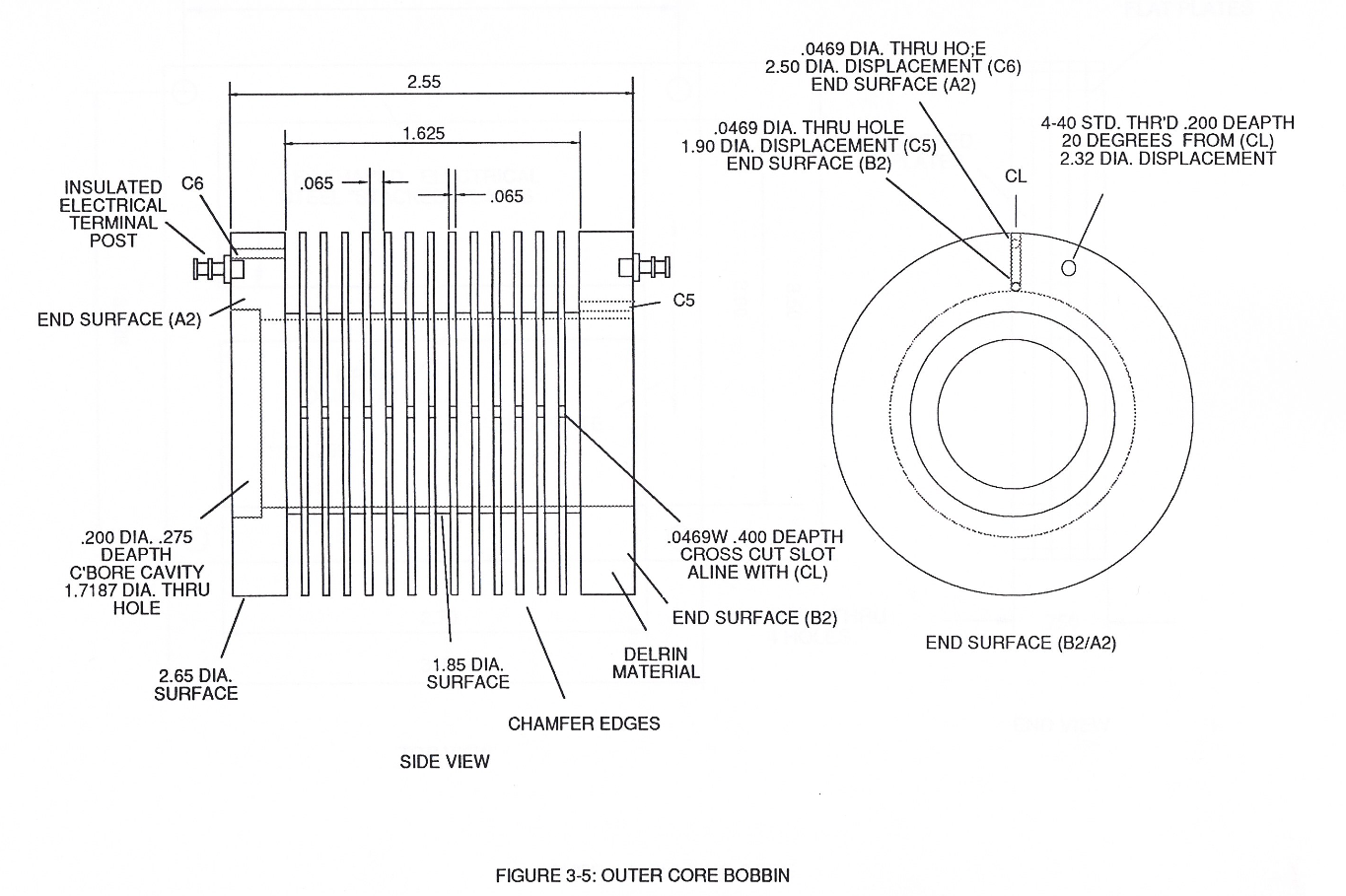](https://stanslegacy.com/uploads/images/gallery/2024-03/uKklpAEgDo1wjKOJ-image-1711247178828-26-17.png) #### 3-6 Pulsing Core [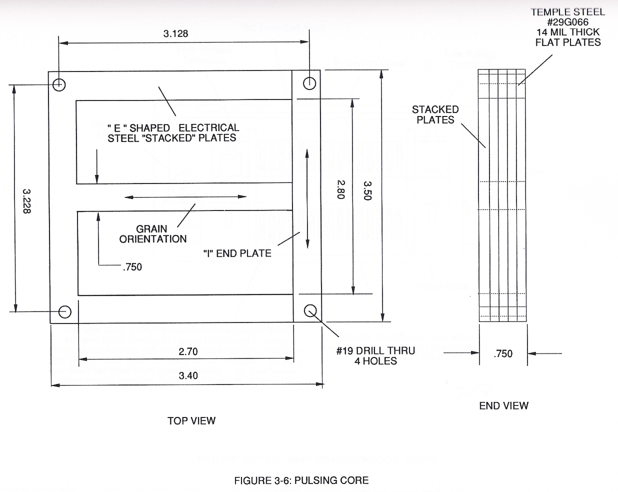](https://stanslegacy.com/uploads/images/gallery/2024-03/EjdzJ8osFvioWjw3-image-1711247216898-26-54.png) #### 3-7 VIC Amp Inhibitor Coil Ass'y [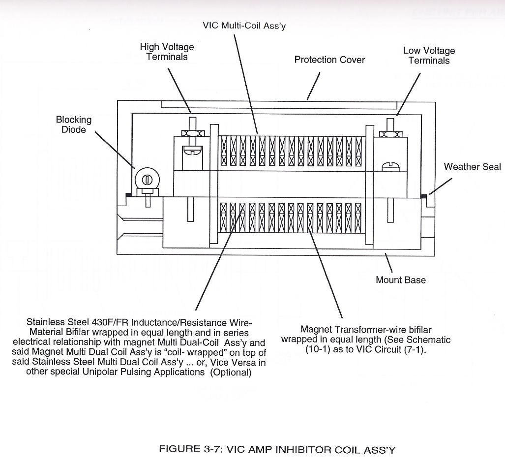](https://stanslegacy.com/uploads/images/gallery/2024-03/O2CN6KjQanuhct3q-image-1711247238552-27-14.png) #### 3-8 Multi-Coil Spool [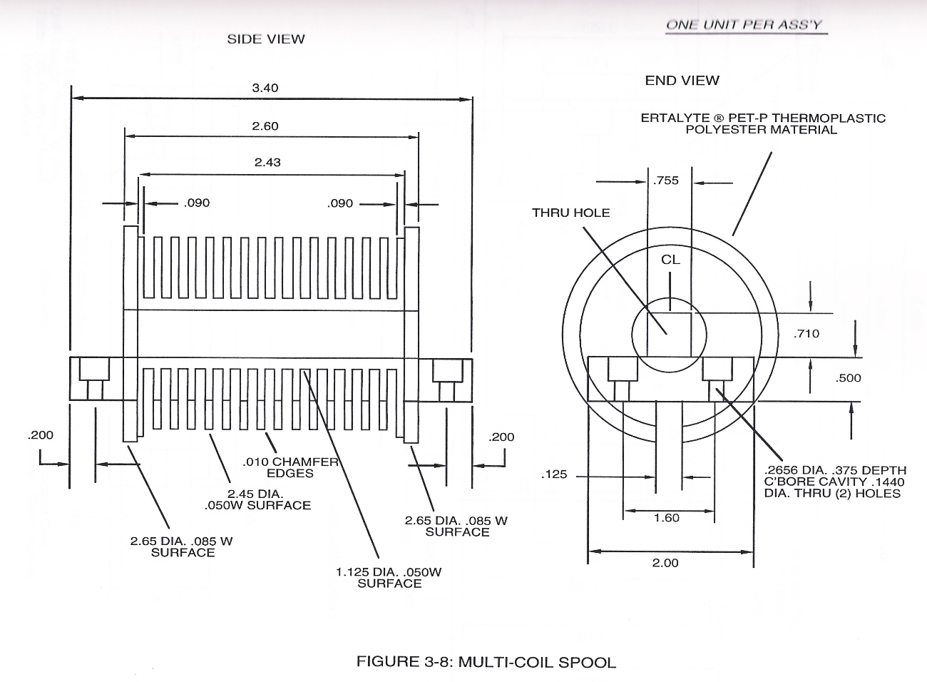](https://stanslegacy.com/uploads/images/gallery/2024-03/aN1CRYSXnhqEsbeA-image-1711247267796-27-45.png) #### 3-9 VIC Mount Base| [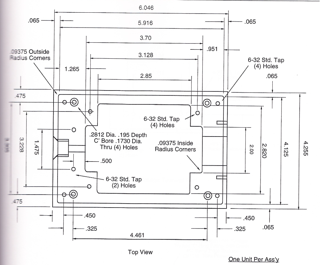](https://stanslegacy.com/uploads/images/gallery/2024-03/aOVQx4Xuf4klXGGq-image-1711247310383.png) | [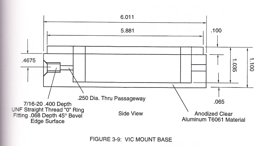](https://stanslegacy.com/uploads/images/gallery/2024-03/OapCunRG0hP7fU1h-image-1711247338589-28-56.png) |
| [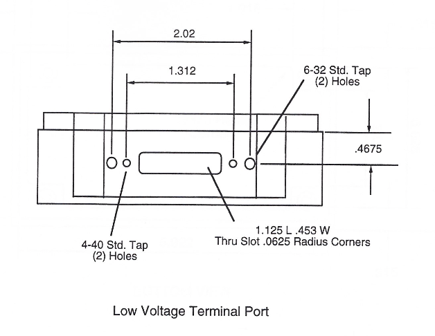](https://stanslegacy.com/uploads/images/gallery/2024-03/crUsj6MNevMDyOoR-image-1711247377552-29-35.png) | [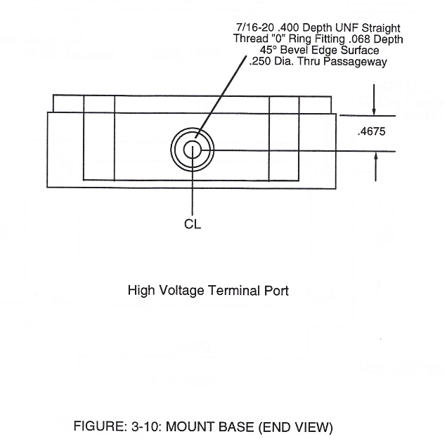](https://stanslegacy.com/uploads/images/gallery/2024-03/4bNCGaVRxZ3rVg77-image-1711247386279-29-44.png) |
| [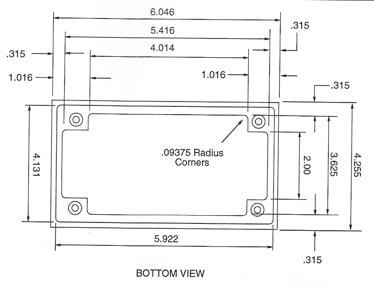](https://stanslegacy.com/uploads/images/gallery/2024-03/PcFU3C5oBSKtSNY3-image-1711247422276-30-20.png) | [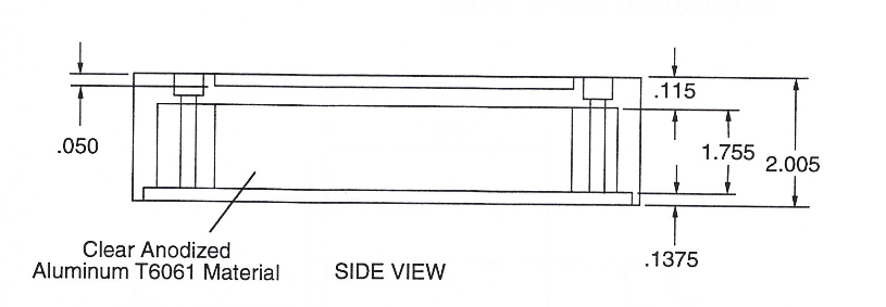](https://stanslegacy.com/uploads/images/gallery/2024-03/WR0rey0Qx6wN1pdc-image-1711247432446-30-30.png) | [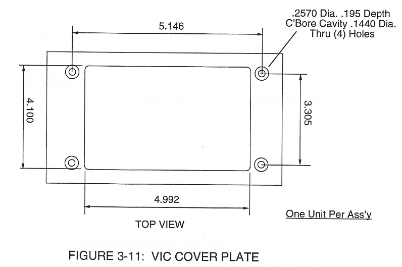](https://stanslegacy.com/uploads/images/gallery/2024-03/3b32XfhWJy63Fm9T-image-1711247443215-30-41.png) |
| [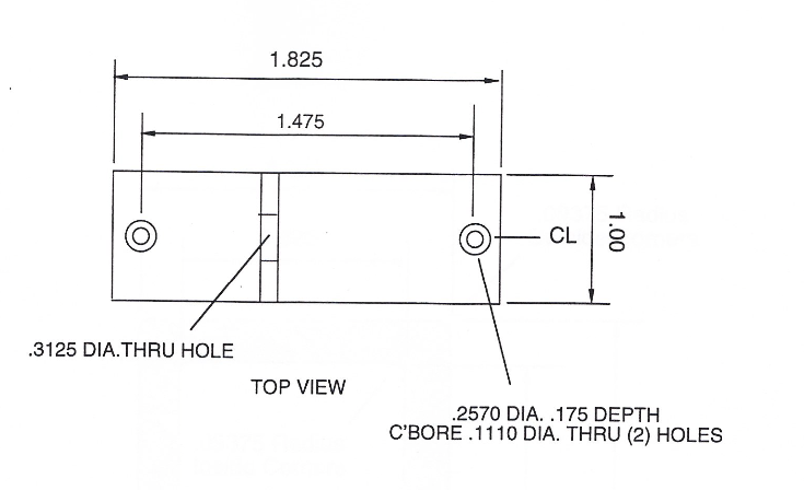](https://stanslegacy.com/uploads/images/gallery/2024-03/3j4LZWnfpeDAZie1-image-1711247469699-31-04.png) | [](https://stanslegacy.com/uploads/images/gallery/2024-03/HjtglwE9VahP3tmH-image-1711247477570-31-15.png) |
| (390) of Figure (3-42) | (100) of Figure (6) [](https://stanslegacy.com/uploads/images/gallery/2024-03/JqeitiAp4qURSnQb-image-1711239500177-18-17.png) |
| **flame projection** (16) of Figure (3B) [](https://stanslegacy.com/uploads/images/gallery/2024-03/lEKSdZZG5WiUvmUW-image-1711235079510-04-35.png) | **Water Fuel Injection System** (10) of Figure (1) [](https://stanslegacy.com/uploads/images/gallery/2024-03/5G6eSwP2K8xbGh7N-image-1711239688578-21-26.png) | (170) of Figure (13)[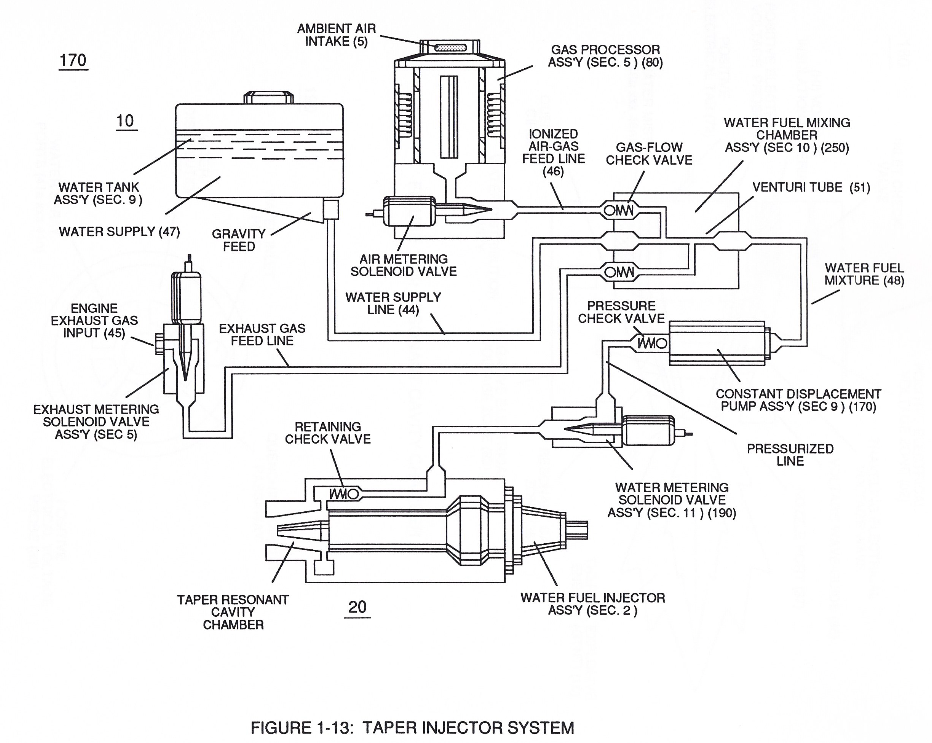](https://stanslegacy.com/uploads/images/gallery/2024-03/OUpVseXIiARHRB16-image-1711239747353-22-24.png) |
allowing water fuel mixture (47/45/46) (48) to be particle aligned by opposite electrostatically charged atoms
...positive charged gas particles (81a xxx 81n) being directed to and attached to negative charged oxygen atom (76) of water molecule (47); while, during the same interim period of time, **negative charged gas particles** (82a xxx 82n) being directed onward to and affix themselves to **positive charged hydrogen atoms** (77a / 77b), as illustrated in (200) of Figure (16). [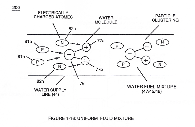](https://stanslegacy.com/uploads/images/gallery/2024-03/5phF31y6vSDzGYIk-image-1711240076581-27-54.png) The resultant water fuel-mixture (48) is, now, pressurized up to and beyond 125 lbs of fluid-pressure by **Fluid Displacement Pump** (170) of Figure (13), as before, to cause and form water fuel-droplets (48a xxx 48n) when water fuel (48) enters into, passes through and beyond spray ports (41a xxx 41n) forming **Quenching Disc Structure** (190) of Figure (15).| **Fluid Displacement Pump** (170) of Figure (13) [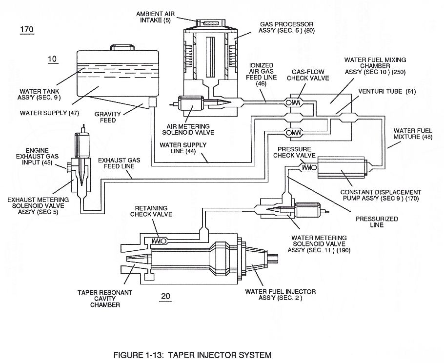](https://stanslegacy.com/uploads/images/gallery/2024-03/Uc94Wno727HBNfNf-image-1711241901925-58-18.png) | Quenching Disc Structure (190) of Figure (15)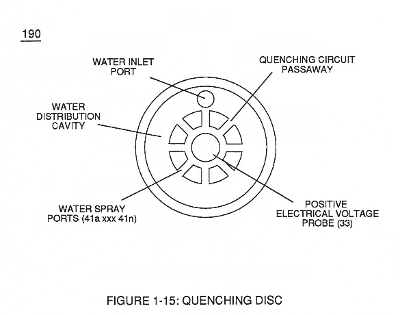 |
The injected **water fuel-droplets** (48a xxx 48n), now, surrounds outer surface area of exposed **positive probe** (33) while entering into **Taper Resonant Cavity** (180), as illustrated in (70) of Figure (3B) as to Figure (14).
| (70) of Figure (3B) [](https://stanslegacy.com/uploads/images/gallery/2024-03/gZ5KPTpzSpn636bH-image-1711242032622-00-30.png) | Figure (14) [](https://stanslegacy.com/uploads/images/gallery/2024-03/lEKSdZZG5WiUvmUW-image-1711235079510-04-35.png) |
| **Electron Ejection Process** (230) of Figure (29) | (80) of Figure (4) [](https://stanslegacy.com/uploads/images/gallery/2024-03/sxDuDQrTfViKX2st-image-1711240439701-33-56.png) |
all sequential gas priming functions occurring progressively in an instant of time.
Subsequent and repetitive formation of applied **gated electrical voltage pulse-train** (210a xxx 210n) of Figure (17) to continued in-flow of **water fuel droplets** (48a xxx 48n) not only sustains and maintains **Hydrogen Fracturing Process** (100) of Figure (6) but, also, regulates **Thermal Explosive Energy** release (16a x 16n) of Figure (14) by attenuating applied voltage amplitude (xxx VL xxx), as graphically shown in Figure (20F) ([WFC Memo 420](https://stanslegacy.com/books/the-birth-of-new-technology/chapter/wfc-420-hydrogen-fracturing-process "WFC 420 - Hydrogen Fracturing Process")).| **Hydrogen Fracturing Process** (100) of Figure (6) [](https://stanslegacy.com/uploads/images/gallery/2024-03/JqeitiAp4qURSnQb-image-1711239500177-18-17.png) | **Thermal Explosive Energy** release (16a xxx 16n) of Figure (14) [](https://stanslegacy.com/uploads/images/gallery/2024-03/lEKSdZZG5WiUvmUW-image-1711235079510-04-35.png) |
| Figure (25) [](https://stanslegacy.com/uploads/images/gallery/2024-03/omxCpQuXn2n0VVRF-image-1711243801341.png) | Figure (29) [](https://stanslegacy.com/uploads/images/gallery/2024-03/hd0GV5mTUN46fgSa-image-1711243903210.png) |
| (390) of Figure (41) | (180) of Figure (14) [](https://stanslegacy.com/uploads/images/gallery/2024-03/lEKSdZZG5WiUvmUW-image-1711235079510-04-35.png) |
| voltage triggering process (210) of Figure (17) [](https://stanslegacy.com/uploads/images/gallery/2024-03/pHJJMAHMYDulX5HH-image-1711242198362-03-15.png) | (100) of Figure (6) |
Electron restriction while varying voltage intensity (Va = Vn) is accomplished by performing several functions simultaneously:
Incoming **pulse-train** (210a xxx 210n) is adjusted to "tune-in" to the Dielectric Properties of Water (47) which allows Resonant Action (see [WFC Memo 424](https://stanslegacy.com/books/the-birth-of-new-technology/chapter/wfc-424-atomic-energy-balance-of-water "WFC 424 - Atomic Energy Balance of Water"), once again) to occur since the Dielectric property of water (*78.54 value*) becomes a integral part of **Electronic Circuit** (110) of Figure (7) as to (220) of Figure (18)| **Electronic Circuit** (110) of Figure (7) [](https://stanslegacy.com/uploads/images/gallery/2024-03/aEKWjdeQv4j5D9sz-image-1711246045987-07-24.png) | (220) of Figure (18) [](https://stanslegacy.com/uploads/images/gallery/2024-03/UbQQXtm822UJY1my-image-1711238945929-09-03.png) |
... forming a capacitor (E7 / E8) in series with Resonant Charging Chokes (56/57) placed on opposite sides of Resonant Cavity Zone (35) as to Figure (7) and (8) . . . forming a Resonant Pulsing Circuit (110) of Figure (7) with step-up **Pulsing Transformer** (33/36), as shown in (220) of Figure (18).
Adjusting Pulse-train (210a xxx 210n) in such a way as to allow pulse off-time (T2) to be synchronized with collapsing and re-formation of electromagnetic field coupling across pulsing transformer (52/53) to produce unipolar pulse frequency (T1a xxx T1n), as illustrated in (220) of Figure (18) as to Figure (17).| (220) of Figure (18) [](https://stanslegacy.com/uploads/images/gallery/2024-03/UbQQXtm822UJY1my-image-1711238945929-09-03.png) | Figure (17) [](https://stanslegacy.com/uploads/images/gallery/2024-03/pHJJMAHMYDulX5HH-image-1711242198362-03-15.png) |
| [](https://stanslegacy.com/uploads/images/gallery/2024-03/ENk0b7D7uh9mDVXX-image-1711236926123-35-23.png) | [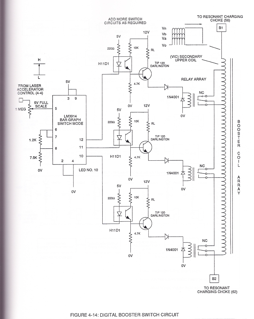](https://stanslegacy.com/uploads/images/gallery/2024-03/2AJ8bEqLZFOJQtAM-image-1711238092887-54-49.png) |
**Sequential Switch Circuit** (59) simply switches in and out **Booster Pickup Coils** (61a xxx 61n) in series electrical hookup with **Secondary Coil** (53) output to elevate voltage intensity across Resonant Charging Chokes (56/57).
Forming Resonant Charging Chokes (56/57) by using Stainless Steel Electro-Inductance wire-material (430F / T304 or equivalent) which, when electrically pulsed transmits voltage intensity while restricting amp flow during Resonant Pulsing operations. Together, the resistive valve of Stainless Steel wire-coil (56/57) and its inductance generated electromagnetic field (62) of Figure (19) opposes the movement of electrons since the dielectric valve of wire-coils (56/57) inhibits electron exchange while the generated inductance field (62) locks onto the electromagnetic field of the electrons ...generated coil inductance field (62) being greater in electromagnetic... \[ends abruptly...\]| [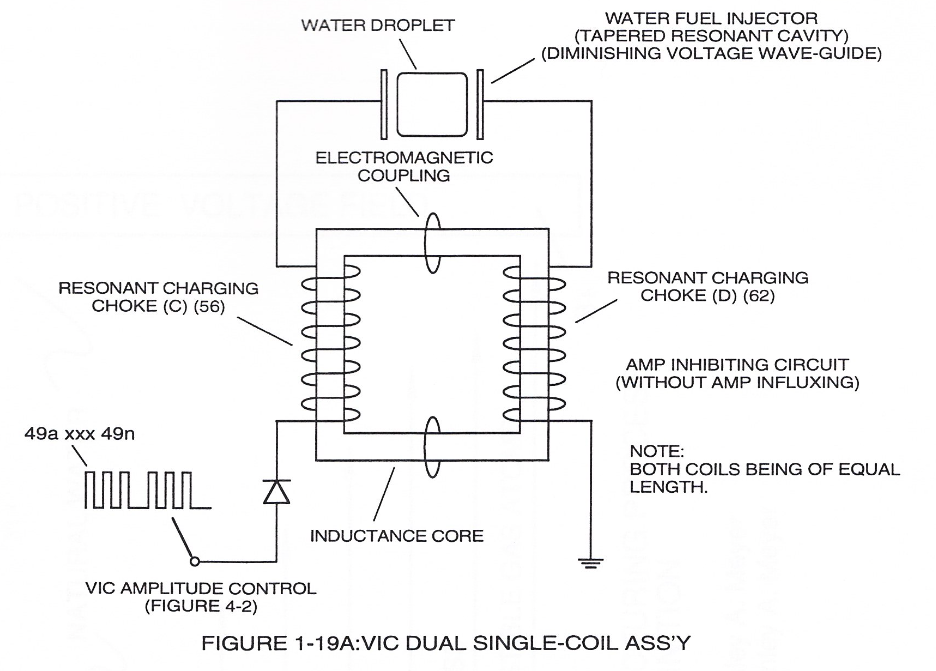](https://stanslegacy.com/uploads/images/gallery/2024-03/ItHbfV0yw5rt3wzS-image-1711238896182-08-12.png) | [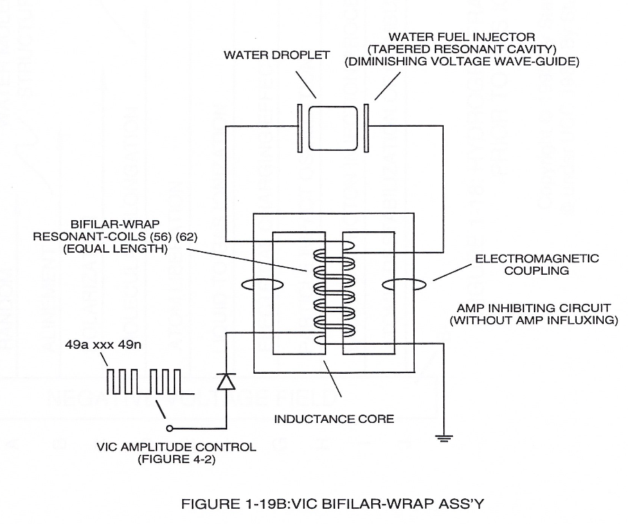](https://stanslegacy.com/uploads/images/gallery/2024-03/9fhLQE7R6ZHcUQyz-image-1711238904577-08-22.png) |
In other words, the inductance and capacitance values of **stainless steel induction coil** (56/57) bypasses voltage drop across its resistive load (ohmic valve of wire).
This induced voltage phenomenon encourages and therefore prevents resonant **pulse frequency** (58) from being impaired or altered while being electrically transmitted to **Resonant Cavity** (180) of Figure (14) via electrical tabs (71) and (72) of Figure (14). [](https://stanslegacy.com/uploads/images/gallery/2024-03/lEKSdZZG5WiUvmUW-image-1711235079510-04-35.png) # Funneling Effect [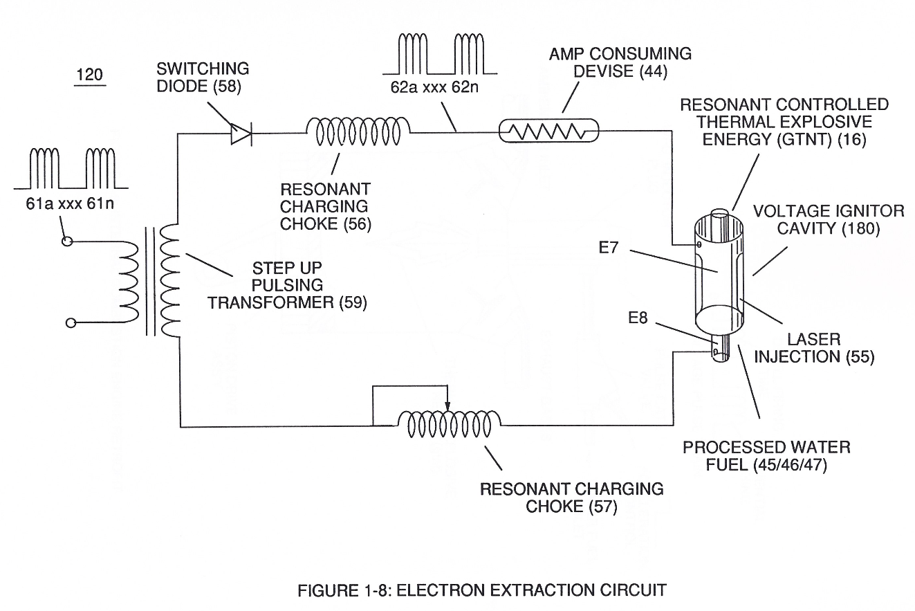](https://stanslegacy.com/uploads/images/gallery/2024-03/O2XDg5jk3UxGd1TD-image-1711234955125-02-31.png)Enhancement of the operational parameters of **Hydrogen Fracturing Process** (100) of Figure (6) is further exemplified when incoming **Resonant voltage-wave** (58) of Figure (18) electrically transmitted across **Resonant Cavity Zone** (35) during water injection cycle... causing **Resonant Cavity Zone** (35) to function and perform as a **voltage wave-guide** (86) of Figure (14) since the gradual decrease in cross-sectional circumference area (85) of Figure (14) is in linear progression ... reducing both voltage surfaces areas (83/84) in parallel space relationship from larger segmental area (85a) to smaller segmental area (85n). [](https://stanslegacy.com/uploads/images/gallery/2024-03/lEKSdZZG5WiUvmUW-image-1711235079510-04-35.png) [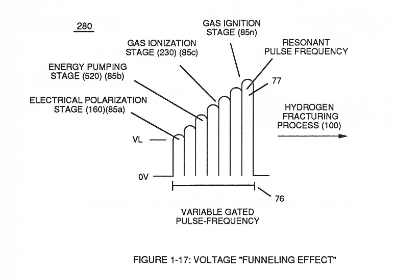](https://stanslegacy.com/uploads/images/gallery/2024-03/cZL77j1fmGg8PZwq-image-1711235293362-08-10.png)This resultant "**Funneling Effect**" (260), now, allows voltage amplitude (Vn) **wave-form** (58) to travel the length of Resonant Cavity Zone (35) from **Start-Point** (85a) to **End-Point** (85n) increasing voltage intensity (xxx VL = Vn) as parallel voltage surfaces (83/84) diminishes in size relationship (85a ~ 85n), as illustrated in (210) of Figure (17). This "progressive" increase in voltage intensity (VL ~= Vn) due to the "**Funneling Effect**", now, allows several gas processing functions to occur in a instant of time:Voltage amplitude level VL of **Pulse-wave** (58) is predetermined (*20,000 V.D.C. typically)* to start and cause **Electrical Polarization Process** (160) at a relative rapid rate of gas production at segmental point (85a) when voltage point (VL xx Va) is reached.
As voltage intensity increases (VL x Va x Vb) onward segmental point (85b), **Energy Pumping Action** (520) of Figure (4-3) ([WFC Memo 424](https://stanslegacy.com/books/the-birth-of-new-technology/chapter/wfc-424-atomic-energy-balance-of-water "WFC 424 - Atomic Energy Balance of Water")) as to (280) of Figure (34) ([WFC Memo 422 DA](https://stanslegacy.com/books/the-birth-of-new-technology/chapter/wfc-422da-wfc-hydrogen-gas-management-system "WFC 422DA - WFC Hydrogen Gas Management System")) is activated to peak performance levels.| (520) of Figure (4-3) [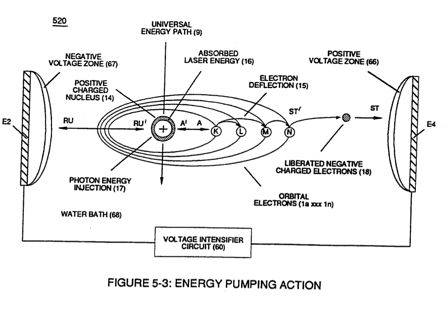](https://stanslegacy.com/uploads/images/gallery/2024-03/gQbpGVKKKqmEbEYT-image-1711236158134-22-35.png) | (280) of Figure (34) [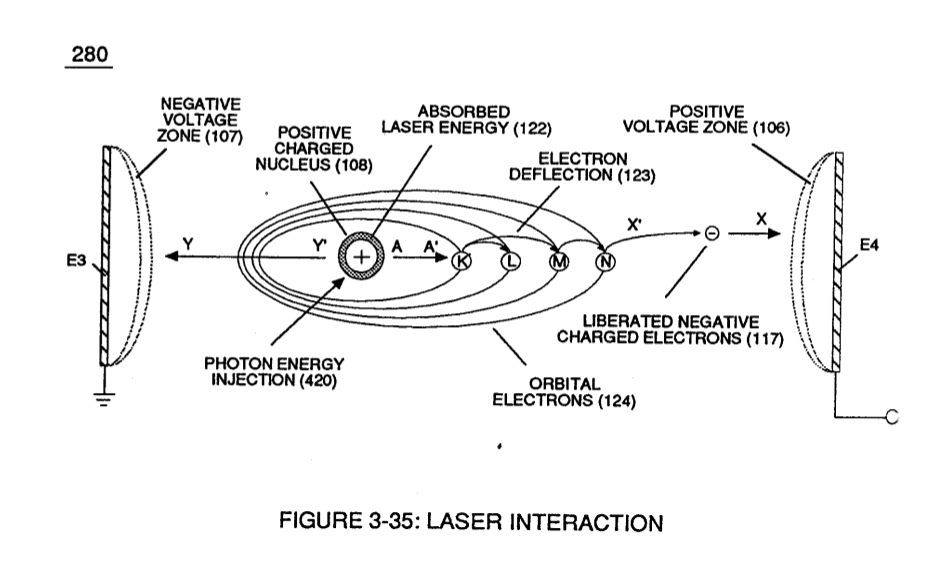](https://stanslegacy.com/uploads/images/gallery/2024-03/HYSxIlsAQa2ancBF-image-1711236265839-24-23.png) |
At segmental point (85c) voltage intensity (VL x Va x Vb x Vc) is increased sufficiently enough to propagate **Gas Ionization Process** (230) of Figure (3-30) ([WFC Memo 422 DA](https://stanslegacy.com/books/the-birth-of-new-technology/chapter/wfc-422da-wfc-hydrogen-gas-management-system "WFC 422DA - WFC Hydrogen Gas Management System")).
[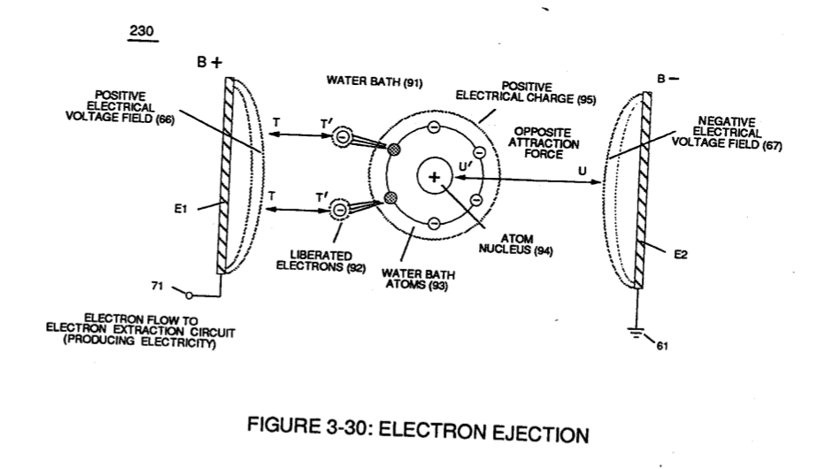](https://stanslegacy.com/uploads/images/gallery/2024-03/pe6afqhEDgTyKAXl-image-1711236372677-26-10.png) At termination point (85), voltage intensity (VL x Va x Vb x Vc x Vn) is, now, increased to the point to cause **Gas Ignition** as **Combustible Gas Atoms** (76, 77a - 77b) which are, then, expelled from **Gas Nozzle Port** (87) of Figure (14) under dynamic pressure to allow **thermal gas expansion** (16) ... releasing thermal explosive energy (gtnt) beyond and away from **Resonant Cavity Chamber** (180), as illustrated in Figure (14). [](https://stanslegacy.com/uploads/images/gallery/2024-03/lEKSdZZG5WiUvmUW-image-1711235079510-04-35.png) To prevent pre-ignition of gases traveling toward **Exit-Port** (87), **Resonant Cavity** (35) open space (open resonant cavity) parallel dimension between positive voltage surface (82) and negative voltage surface (83) is small enough (typically .010 or so) to function as a **Quenching Circuit**, as illustrated in Figure (24SD) (missing image) ([WFC Memo 420](https://stanslegacy.com/books/the-birth-of-new-technology/chapter/wfc-420-hydrogen-fracturing-process "WFC 420 - Hydrogen Fracturing Process")). To increase energy levels (16a xxx 16L = 16n) of **Hydrogen Fracturing Process** (100) as to (390), even further, simply switch-on additional Booster Coils (61a x 61L - 61n) in sequential order to increase voltage intensity (VL ~ Vn ~ Vm) to higher magnitude of "**Electrical Force**" (Vma xxx Vmn) which is due to the inductance/capacitance values of each succeeding coil-structure (61a x 61n) forming **Booster coil-Assembly** (250), as illustrated in (240) of Figure (20).| [](https://stanslegacy.com/uploads/images/gallery/2024-03/ENk0b7D7uh9mDVXX-image-1711236926123-35-23.png) | [](https://stanslegacy.com/uploads/images/gallery/2024-03/2AJ8bEqLZFOJQtAM-image-1711238092887-54-49.png) |
This resultant "**Shunting Effect**", now, allows voltage intensity (Vma = Vmn) to be placed across **Resonant Cavity Zone** (35) to not only compensate for water impurity that might alter the operational parameters of **Hydrogen Fracturing Process** (100) as to (390) but, also, provide "Instant" "Power-Boost" when needed.
| [](https://stanslegacy.com/uploads/images/gallery/2024-03/lEKSdZZG5WiUvmUW-image-1711235079510-04-35.png) | [](https://stanslegacy.com/uploads/images/gallery/2024-03/Qk1Jl0AL2SdmIEMn-image-1711237351260.png) |
The established "Power Boost" energy level (16a xxx 16n) is changeable, however, by, simply, electrically moving or displacing (back and forth movement) **Core-Slug** (73) to another stop-location (72)... adjusting energy-level (16a xxx) on demand.
In alternate form, **Core-Slug** (73) is replaced by a series of **Choke Coils** (77a xxx 77n) arranged in such a way as to increase voltage Intensity (Voltage Pulse Amplitude) (VL ~ Vn xxx) digitally by sequentially switching-on / switching -off Choke Coils (77a xxx 77n) to allow applied Voltage Intensity (VL ~ Vn xxx) to be placed across **Voltage Expander Coils** (78a xxx 78n) in direct relationship to electrically energized shunt-coil (76).
For example, as adjacent **Shunt-Coil** (76b) is switch-on while, simultaneously, **Choke Coil** (76a) is switch-off by **Electronic Switch Circuit** (79), Voltage Intensity (VL ~ Vn xxx) is increased due to inductance / capacitance of **Voltage Expander Coil** (78a) which is, now, added to **Electrical Circuit** (250) by electrical pathway (82a) since **electromagnetic coupling field** (76b) prevents electron flow to cause open circuit (82b)... (missing content) thereby establishing **Voltage Level Logic Function** (260) which is electronically transferable in sequential order (260a xxx 260n) by **Laser Acceleration Control Circuit** (4-4) of (220) of Figure (18). [](https://stanslegacy.com/uploads/images/gallery/2024-03/Xfkuluj5Fro9DYEl-image-1711238220068-56-57.png) thereby, attenuating voltage amplitude (voltage intensity) beyond **Secondary Coil** (53) **voltage levels** (71), as illustrated in (220) of Figure (18).Attenuating variable voltage amplitude (72a xxx 72n) in conjunction with incoming **gated pulse-train** (210a xxx 210n), now, expands **gated pulse width** (76a xxx 76n) as voltage amplitudes (Vo xxx Vn) increases, forming step up voltage wave Form (77) of Figure (17).
[](https://stanslegacy.com/uploads/images/gallery/2024-03/EmNtWjdZJcIuRmXm-image-1711238704911-05-02.png) This newly formed synchronized and repetitive dual expanding voltage wave form (77a xxx 77n) is further enhanced by "**Funneling Effect**" (260)... maximizing voltage dynamic across **Resonant Cavity** (35) always subjecting and exerting increase "**Electrical-Stress**" (SS'-RR' / TT'-UU') of opposite polarity across **Hydrogen Fracturing Process** (100 / 390) to the point of gas ignition. [](https://stanslegacy.com/uploads/images/gallery/2024-03/Qk1Jl0AL2SdmIEMn-image-1711237351260.png) # Amp Inhibiting Circuit Vs Voltage Enhancement #### Amp Inhibiting Circuit Vs Voltage Enhancement [](https://stanslegacy.com/uploads/images/gallery/2024-03/UbQQXtm822UJY1my-image-1711238945929-09-03.png)Beyond amp restricting characteristic of said Amp Inhibiting Circuit of Figure (1-18) as to VIC Dual Single-coil Assembly (Figure 1-19A) and VIC Bifilar-Wrap Coil Assembly (Figure 1-19B), the spiral-wrapped coils being paired together, also, causes voltage level enhancement beyond applied voltage input since the "**Distributed Capacitance**" (Cl xxx Cln =C2a xxx C2n) / "Distributed Inductance" (FL1a xxx FL1n = FL2a xxx FL2n) of said "Bifilar" wrapped coils encourages the compounding effect (*increasing magnetic field-strength during each pulsing cycle*) of electromagnetic field-strength (Rpla xxx Rpin = Rp2a xxx Rp2n) (*mutual induction*) when applied **Pulse-Voltage Frequency** (49a xxx 49n) passes through the positive energized **Resonant Charging Choke** (56).| Figure 1-19A [](https://stanslegacy.com/uploads/images/gallery/2024-03/ItHbfV0yw5rt3wzS-image-1711238896182-08-12.png) | Figure 1-19B |
[](https://stanslegacy.com/uploads/images/gallery/2024-03/i811WuUTRUfZRdsS-image-1711239008934.png)Furthermore, the paired coils-wires opposite voltage potential \[*positive electrical attraction force (B+) equaling negative electrical force (B-)*\] \[herein called "**Electrical Stress**" (SS' = RR") as to (160) of Figure (3-26)\] are always equal in electrical magnitude/electrical intensity since the wire-length of each coil are the same.
Pulse-Voltage repetition rate sets up the step-up **electrical charging effect** (Figure 1-3) since the "Resonant Cavity" *functions as a Capacitor ER*) due to the dielectric value (*Resistance to amp flow*) of water which becomes an integral part for the VIC Circuit, as so illustrated in (650) of Figure (7-4).| Figure 1-3 [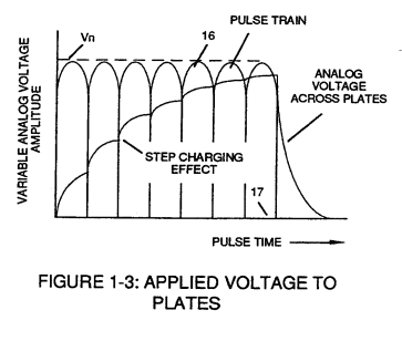](https://stanslegacy.com/uploads/images/gallery/2024-03/xe9bT7LjJcDamtiN-image-1711239254526.png) | (650) of Figure (7-4) [](https://stanslegacy.com/uploads/images/gallery/2024-03/cKpmcgCavj8oAP8N-image-1711239279648.png) |
The resultant voltage enhancement (**Voltage Amplitude**) can exceed 40 kilovolts to instantly convert water (droplets) into **thermal explosive energy** (gtnt), as so illustrated in **voltage Intensifier Circuit Diagram** (Figure 1-18).
[](https://stanslegacy.com/uploads/images/gallery/2024-03/UbQQXtm822UJY1my-image-1711238945929-09-03.png) > Both VIC Dual Single-Coil (Figure 1-19A) and VIC Bifilar-Wrap Coil (Figure 1-19B) function similarly without incurring amp influxing. (*See WFC U.S. Patent Validation Report titled "Natural Water Hydrogen Generation System filed September 16, 1981*)| Figure 1-19A [](https://stanslegacy.com/uploads/images/gallery/2024-03/ItHbfV0yw5rt3wzS-image-1711238896182-08-12.png) | Figure 1-19B |
The energy contained in a gallon of water exceeds 2.5 million barrels of oil when equated in terms of atomic energy. Water, of course, is free, abundant, and energy recyclable.
# Energy Pumping Action [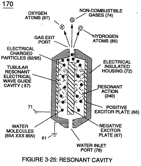](https://stanslegacy.com/uploads/images/gallery/2023-12/vWXYcqouOi1pFz4V-image-1702347406917.png) Once unlike atoms of the **Water Molecule** (210) separates into its component gases by way of **Electrical Polarization Process** (160), the newly liberated and subsequently free floating **hydrogen** (77 a/b), **oxygen** (76), and **dissolved air gases** (97) (see [WFC memo 420 DA](https://stanslegacy.com/books/the-birth-of-new-technology/chapter/wfc-423da-water-fuel-injection-system "WFC 423DA - Water Fuel Injection System") Figure 325) submerged in **water bath** ( 68) are further subjected to **pulse-voltage stimulation** ( SS' / RR ' \_ IT ' / UU ' ) ... exerting **Electrical Pressure** of opposite polarity on the atomic level, as illustrated in Figure (5-1) as to Figure (5-2) and Figure (5-8).| Figure (5-1)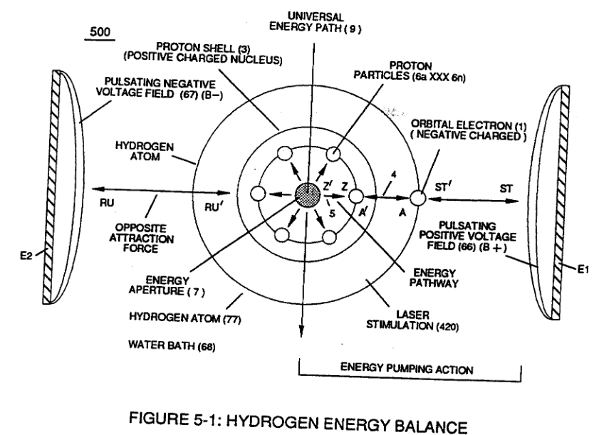 | Figure (5-2)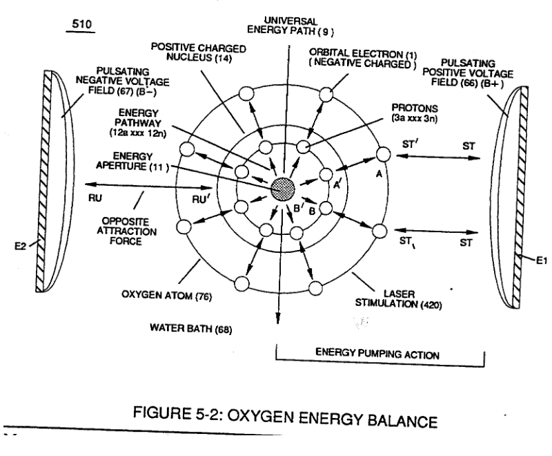 |
| Figure (5-8)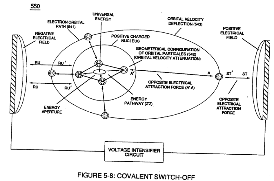 |
**Applied voltage fields** (66-El/67-E2) causes and forms both **opposite attraction forces** (ST - ST') and (RU - RU') across exposed **Hydrogen Atom** (77) since the **negative charged hydrogen electron** (1) is attracted and deflected toward **stationary positive voltage field** (66);
...while, **simultaneously**, positive charged **hydrogen proton** (3) (**Hydrogen Nucleus**) is attracted and moved in opposite direction toward **stationary voltage field** (67) ... causing elongation of the orbital path of moving **electron** (1) ... changing the time share rate of the electron ... applying and superimposing **electrical tension** (4) onto **opposite attraction force** (AA') that exist between the **negative charged** **orbital electron** (1) and **positive charged** **Proton** (3) ... which, in sequence, applies and superimposes **electrical tension** (5) unto **opposite attraction forces** (ZZ') that exists and occupies space between **proton particles masses** (6a xxx 6n) and **Energy Aperture** (7).Interlocked together, the resultant "**Electrical Tension of Forces**" (4/5) is directly related to **Voltage Intensity** (ST - ST' / RU - RU' ) of **applied voltage fields** (66/67) which is variable as to **applied voltage amplitude** ( Vo xxx ). Increasing **voltage amplitude** ( xxx Vn) still further increases **electrical tension** (4 / 5 ) being applied to **Energy Aperture** (7) or vice versa.
[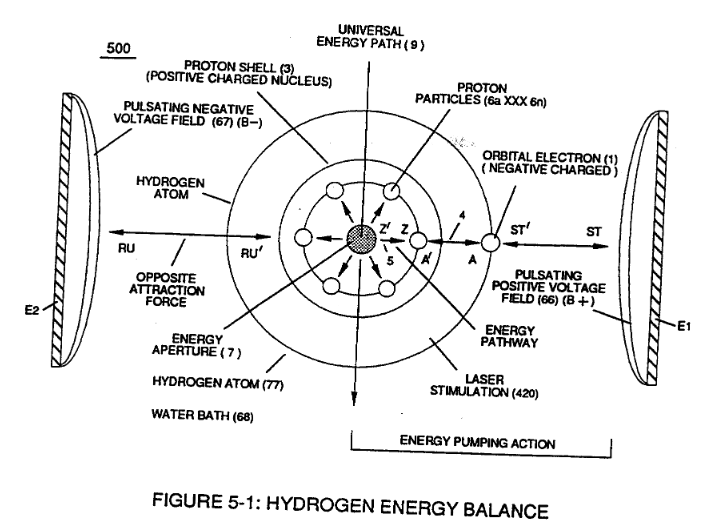](https://stanslegacy.com/uploads/images/gallery/2023-12/Hpg7rh0OweIs9pZ4-image-1702273184697.png)This established increase or decrease in **Electrical Pressure** (4 / 5 ), now causes **Energy Aperture** (7) to either enlarge or become smaller as to applied voltage amplitude (VO xxx Vn), respectively. Once **applied voltage pulse of opposite polarity** (66/67) is terminated during pulse off-time, then **Energy Aperture** (7) automatically adjusts to maintain a given energy level since each aperture oscillation (*aperture expansion*) emits a discrete amount of **Universal Energy** (9) into **proton** (3) via **energy pathway** (ZZ'), as illustrated in Figure (5-1). Repetitive pulsing of applied voltage fields (66/67), now, oscillates **Energy Aperture** (7) to emit even a greater amount of **Universal Energy** (9a xxx 9n) into the energy spectrum of the **proton nucleus** (3) to be absorbed ... thereby, increasing the energy level of hydrogen atom still further .... deflecting **hydrogen electron** (1) to a higher energy state, as illustrated in (520) of Figure (5-3). [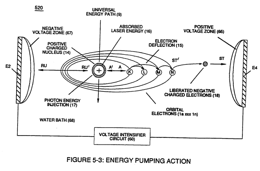](https://stanslegacy.com/uploads/images/gallery/2023-12/HIlTUupmsMJXZJNj-image-1702347723376.png) The resultant energy state of increase is directly related to applied pulse voltage frequency at a predetermined Voltage level. Likewise, **liberated oxygen atom** (76) and other **dissolved air gases** (97) submerged in **water bath** (68) undergo and experience similar **Energy Pumping Action** (520) (*aperture oscillation*) of their respective **Energy Aperture** (11a xxx 11n) when exposed to **voltage stimulation** (66/67), as further illustrated in Figure (5-2). [](https://stanslegacy.com/uploads/images/gallery/2023-12/sQZu9bYClWIgvXMt-image-1702347456919.png) In this phase of application, **opposite attraction force** (BB') provides a **energy transfer path** (12) to each respective **proton** (3a xxx 3n) from **energy aperture** (11) which is centrally formed during proton grouping ... establishing **nucleus** (14) of Figure (5-2). # Resonant Propagation These highly energized and liberated **water bath atoms** (76n7/97), now, causes **Resonant Action** to occur at a progressive rate during continued voltage stimulation ... giving way to the following operational parameters of hydrogen gas production for energy utilization from natural water: **Resonant Action** (21) (*point of particle oscillation*) occurs when applied **pulse voltage frequency** (46) of Figure (5-5) is adjusted to "tune-in" to the **Dielectric Resonance** of water via **voltage Intensifier Circuit** (60) of Figure (5 -3);| (46) of Figure (5-5) [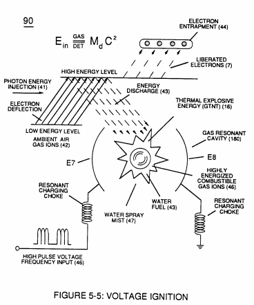](https://stanslegacy.com/uploads/images/gallery/2023-12/zUO1zQkHun2m7Lvy-image-1702519375512.png) | (60) of Figure (5 -3) [](https://stanslegacy.com/uploads/images/gallery/2023-12/iG7GtpwXB0vKu9hN-image-1702519392526.png) |
**applied voltage amplitude** (Vo xxx Vn) which is independent of **Resonance Frequency** is adjusted to cause water bath atoms to momentarily enter into Liquid-to-gas ionization state .... ejecting **negative charged electrons** …forming **positive charged atoms** having missing electrons ... forming **negative charged atoms** by electrons capture; as illustrated in (520) in Figure (5-3) as to Figure (5-4A) and Figure (5-4B).
| (520) in Figure (5-3) [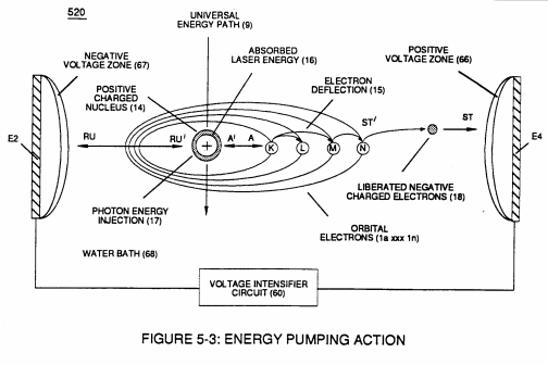](https://stanslegacy.com/uploads/images/gallery/2023-12/Oqco1nr4S6cc5HEs-image-1702519402415.png) | Figure (5-4A/B) [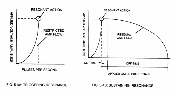](https://stanslegacy.com/uploads/images/gallery/2023-12/L2njK0Voh8648wuv-image-1702519415413.png) |
**Resonant Action** (21), **Compounding Action** (22), **Laser Injection** (17). and **Energy Pumping Action** (520), Now, allows the production of hydrogen and oxygen gases from water in geometrical progression to set up **Hydrogen Fracturing Process** (90). as illustrated in Figure (5-4C) as to Figure (5-5).
| Figure (5-4C) [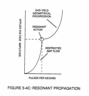](https://stanslegacy.com/uploads/images/gallery/2023-12/SDTj0NCxBK6NQbxr-image-1702519444605.png) | Figure (5-5) [](https://stanslegacy.com/uploads/images/gallery/2023-12/zUO1zQkHun2m7Lvy-image-1702519375512.png) |
Once a quantum amount of thermal explosive energy (gtnta xxx gtntn) is released then the combustible gases return to stable state by forming de-energized water mist (531) as shown in (530) of Figure (5-6).
# Energy Recycling Spectrum Once expelled into **Earth Atmosphere** (541), the energy spent (partly de-energized water molecule atoms) water mist (531) is re-exposed to **Sun Energy** (534) to allow and cause **Photon Energy Absorption Process** (532) of Figure (5-7) that, now, re-vitalizes and returns de-energized **Water Molecule Atoms** (531a xxx 531n) to **Stable Energy State** (538) when spent water mist (531) undergo **Water Evaporation Process** (531) to form **Moisture Cloud Formations** (533) which, when and after formed, are continually exposed to incoming **Sun Rays** (539a xxx 539n) until **Rain Droplets** (535) return newly re-energized water molecules (538a xxx 538n) to **Earth Water Supply** (536) ... completing **Open Ended Energy Recycling Spectrum** (530) for **Energy Re-use**, as further illustrated in (530) of Figure (5-6).| Figure (5-6) [](https://stanslegacy.com/uploads/images/gallery/2023-12/J5ivctUoOAG7t3jY-image-1702348814205.png) | Figure (5-7) 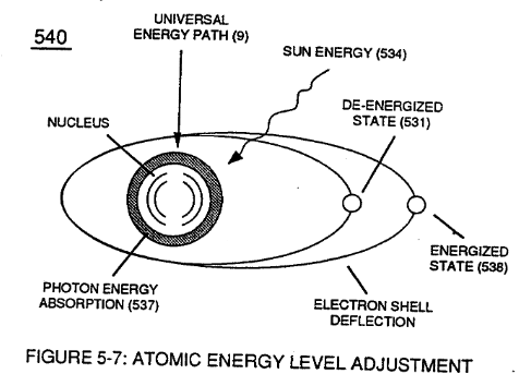 |
**Photon Energy Absorption Process** (531) of Figure (5-7) , of course, can occur in an instant of time.
# In Application of Usage The **Hydrogen Fracturing Process** (390) of Figure (3-42) simply triggers and releases atomic energy (gtnt) from natural water (85) of Figure (3-26) by retarding and preventing the reformation of the water molecule being subjected to sub-critical state (520) of Figure (5-3) during thermal gas ignition (100) of Figure (4-8) as to (70) of Figure (4-5). [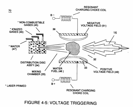](https://stanslegacy.com/uploads/images/gallery/2023-12/IsvWutMXeOlxWkLI-image-1702519901204.png)| (390) of Figure (3-42) [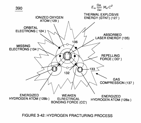](https://stanslegacy.com/uploads/images/gallery/2023-12/CZe2zftk1Dp0BBvw-image-1702519795047.png) | (85) of Figure (3-26) [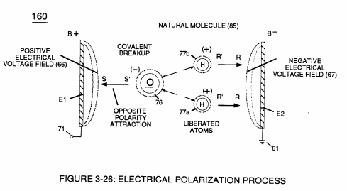](https://stanslegacy.com/uploads/images/gallery/2023-12/2QoSS4pG3a77LJVt-image-1702519823742.png) |
| (520) of Figure (5-3) [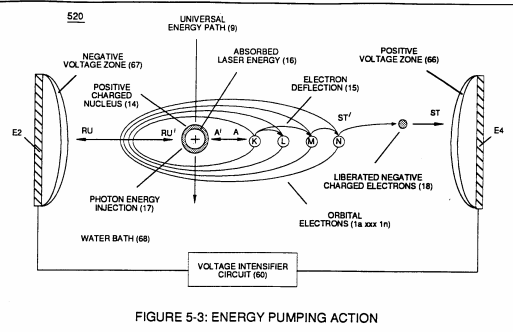](https://stanslegacy.com/uploads/images/gallery/2023-12/IyL70aGTs4VOotGJ-image-1702519939084.png) | (100) of Figure (4-8) [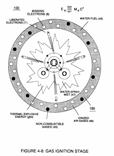](https://stanslegacy.com/uploads/images/gallery/2023-12/P1cirx2omIdNq2Ua-image-1702519954690.png) |
| (110) of Figure (4-9) [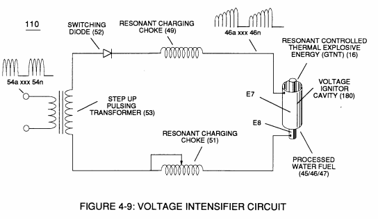](https://stanslegacy.com/uploads/images/gallery/2023-12/4beST04VDlYoiwXb-image-1702520001126.png) | (550) of Figure (5-8) [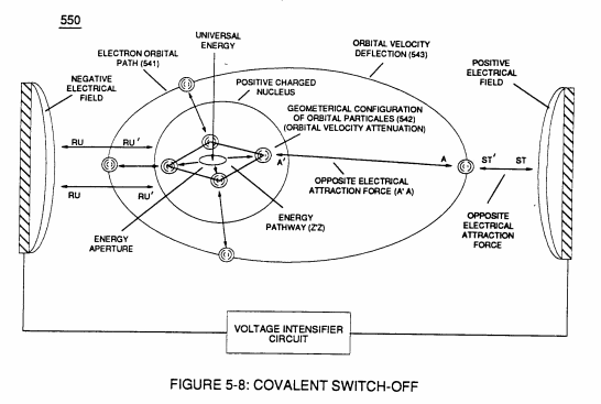](https://stanslegacy.com/uploads/images/gallery/2023-12/tz995Rm6VrIc4iKg-image-1702520027212.png) |
| (500) of Figure (5-1) [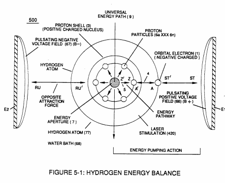](https://stanslegacy.com/uploads/images/gallery/2023-12/6cLMBfn2nDFWwCHO-image-1702520109204.png) | (510) of Figure (5-2) [](https://stanslegacy.com/uploads/images/gallery/2023-12/qG9F3mEsOFCtlHa6-image-1702520119631.png) |
| 610 of Figure 6-4 [](https://stanslegacy.com/uploads/images/gallery/2023-12/tLxmTBtmYxpY8dyK-image-1702349180838.png) |
| (230) of Figure (3-30) [](https://stanslegacy.com/uploads/images/gallery/2023-12/cF89fxUDCNunnpxy-image-1702520311515.png) | (270) of (3-34) [](https://stanslegacy.com/uploads/images/gallery/2023-12/A1kD3NlNqb3FWBMp-image-1702520326182.png) |
| (57) of Figure (6-2) [](https://stanslegacy.com/uploads/images/gallery/2023-12/yfkyykTD8kyZ0ZlP-image-1702321431762.png) | Figure (6-4) [](https://stanslegacy.com/uploads/images/gallery/2023-12/f3grG5km4kIAHtfE-image-1702520278830.png) |
The energy contained in a gallon. of water exceeds 2.5 million barrels of oil when equated in terms of atomic energy. Water, of course, is free, abundant and energy-recyclable.
# Covalent Switch-Off**Covalent Switch-Off** occurs when deflected and elongated **Orbital Electron Pathway** (541) reaches a point where applied **Opposite Electrical Stress** (ST-ST'/RU-RU') (A-A’/Z-Z') is sufficient enough to cause the **Gyroscopic Action** (542) of **Nucleus Particles** (543a xxx 543n) to be reduced in orbital spin-velocity ...
| (210) of Figure (3-27) (Memo WFC 422DA) [](https://stanslegacy.com/uploads/images/gallery/2023-12/fMMnHIaZBDjAFUmj-image-1702349506302.png) | (160) of Figure (3-26) (Memo WFC 422DA) [](https://stanslegacy.com/uploads/images/gallery/2023-12/y88fT39FOnXJYdIM-image-1702349520583.png) |
| (550) of Figure (5-8) [](https://stanslegacy.com/uploads/images/gallery/2023-12/pS1NrS0BbeVEk3BC-image-1702349549558.png) |
... allowing and maintaining **Stable Energy -State** of the atom even if other energy stimuli are not available beyond the physical embodiment of the atom…such as the absent of sunlight (**Photon**) absorption. *See Appendix (B) Note (3).*
#### *Appendix B* > Note 3): **Universal Energy** (9) of Figure (5-10) being a continuous energy potential (source) (C2) coming into our space continuum and creating and sustaining/maintaining our expanding universe, as so extrapolated via mass equation E=MC2. > > Whereby, **Universal Energy** (C2) having native intelligence to create mass (M) (to cause electromagnetic wave-vectoring - photon structuring \_ electron to proton grouping to form atoms - molecular arrangements to bring-on chemical processes to sustain life) which, in turns, emits **radiant energy** (E) under different stimuli conditions ... > > example, particle oscillation as a energy generator by way of "**Electrical Stress**". # Energy Aperture of the Atom **Energy Aperture** (7) of Figure (5-8) exists in all atomic structures (individual atoms) and functions as a one-way energy valve when the **Incoming Energy Vortex** transfers a given or discrete amount of "**Universal Energy**" (having higher energy potential) into the **Energy Spectrum of the Atom** to compensate for and maintain "**Atomic Energy Equilibrium**" during either "**quiescent**" or "**active**" state of tickling particle oscillation as an energy generator| (7) of Figure (5-8) [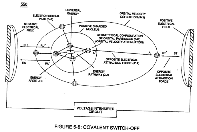](https://stanslegacy.com/uploads/images/gallery/2023-12/G9eP63jhaqLqIdLD-image-1702350074566.png) |
(example, bouncing electrons in a sinusoidal-wave form to its orbital path to cause electromagnetic wave oscillations) ...
allowing the influx of "**Universal Energy**" (Light Energy) to vortex inwardly toward the center part of the "**Gyroscopic**" orbital spin-velocity of **nucleus particles** being displaced about a common axis of rotation ... the resulting "**Gyroscopic Action**" regulating the **inward flow** or **flow intensity** of "**Universal Energy**" in direct relationship to the orbital spin-velocity of the geometrical particle-structuring (interlocking particles grouped in space relationship to each other) set in orbital motion, as illustrated in (570) of Figure (5-10).| (570) of Figure (5-10) [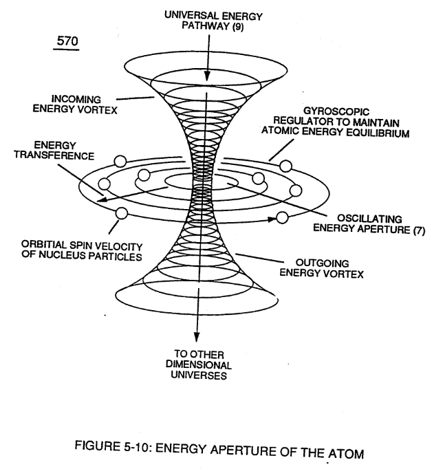](https://stanslegacy.com/uploads/images/gallery/2023-12/YLUI03voNGsksSYc-image-1702350038120.png) |
(c) is the quantum of electromagnetic energy carried in a small amount and moving with the speed of light, as so illustrated in Figure (5-11).
**Optical Photon** having energies corresponding to wavelengths between 120 and 1800 nanometers ... thus, propagating sun's light or its direct rays (539a xxx 539n) of Figure (5-6).| Figure (5-6) [](https://stanslegacy.com/uploads/images/gallery/2023-12/J5ivctUoOAG7t3jY-image-1702348814205.png) |
| (534 & 540) of Figure (5-7) [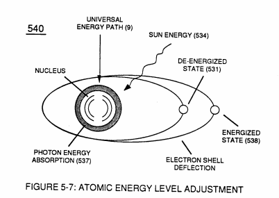](https://stanslegacy.com/uploads/images/gallery/2023-12/EFVObfXblpgT334a-image-1702520608862.png) | (520) of Figure (5-3) [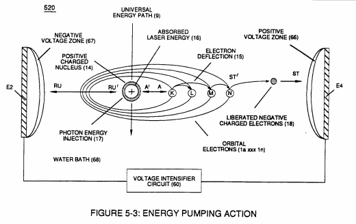](https://stanslegacy.com/uploads/images/gallery/2023-12/2QpfTL6Aw2ym7AMX-image-1702520667463.png) |
| (570, 7, 9) of Figure (5-10) [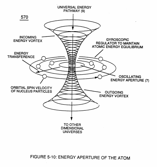](https://stanslegacy.com/uploads/images/gallery/2023-12/u439ax4ROdFqxaS4-image-1702520727814.png) | (550) of Figure (5-8) [](https://stanslegacy.com/uploads/images/gallery/2023-12/pO1E1NbCBxICDUBv-image-1702520739603.png) |
| (970) of Figure (5-12) [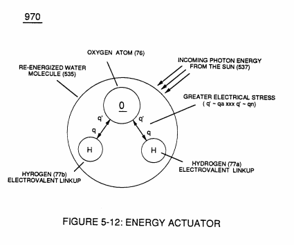](https://stanslegacy.com/uploads/images/gallery/2023-12/3W3SEuLTkN1IanlR-image-1702520758413.png) | (540) of Figure (5-7) [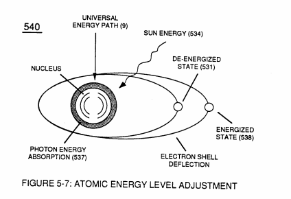](https://stanslegacy.com/uploads/images/gallery/2023-12/bjrujugfcAugqxEr-image-1702520771875.png) |
| (530) of Figure (5-6) [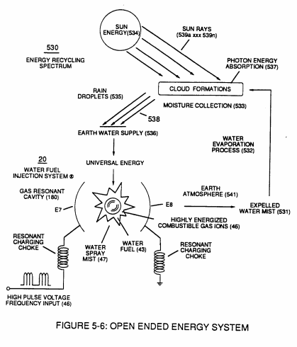](https://stanslegacy.com/uploads/images/gallery/2023-12/68ou3q4QTmEs3pBJ-image-1702519555360.png) |
| [](https://stanslegacy.com/uploads/images/gallery/2023-12/hSvsyRGdmn2cIWQ3-image-1702520868861.png) | [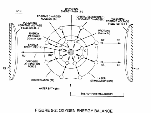](https://stanslegacy.com/uploads/images/gallery/2023-12/GIgs5UHZ944KHSyq-image-1702520879409.png) | [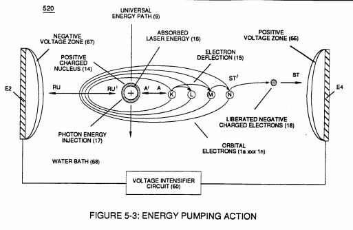](https://stanslegacy.com/uploads/images/gallery/2023-12/lH0J1xDuTO0UUCD0-image-1702520889137.png) |
| [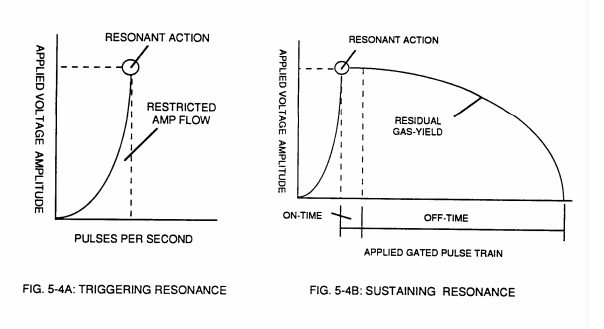](https://stanslegacy.com/uploads/images/gallery/2023-12/QDPKJy2iTCiRwSnA-image-1702520897782.png) | **[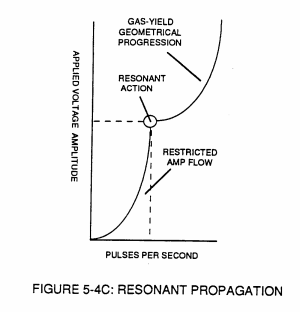](https://stanslegacy.com/uploads/images/gallery/2023-12/haT0KIY6zWzktiML-image-1702520915783.png)** | [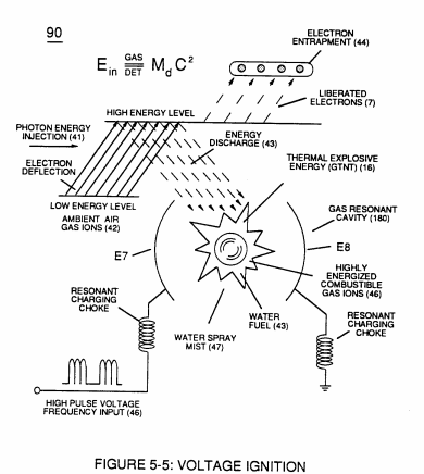](https://stanslegacy.com/uploads/images/gallery/2023-12/WMN89RerA4Svig35-image-1702520937011.png) |
| [](https://stanslegacy.com/uploads/images/gallery/2023-12/68ou3q4QTmEs3pBJ-image-1702519555360.png) | [](https://stanslegacy.com/uploads/images/gallery/2023-12/bjrujugfcAugqxEr-image-1702520771875.png) | [](https://stanslegacy.com/uploads/images/gallery/2023-12/pO1E1NbCBxICDUBv-image-1702520739603.png) |
| [](https://stanslegacy.com/uploads/images/gallery/2023-12/gjhkx8FhJnPzMzRt-image-1702521036076.png) | [](https://stanslegacy.com/uploads/images/gallery/2023-12/nUNJwiZoZa4CO5Te-image-1702521046706.png) | [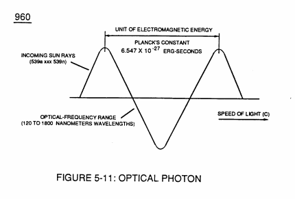](https://stanslegacy.com/uploads/images/gallery/2023-12/EIoRLOIrRY4wNG4s-image-1702521056188.png) |
| [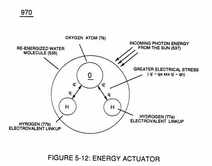](https://stanslegacy.com/uploads/images/gallery/2023-12/QiMewtetEvXCWDaq-image-1702521067117.png) |
All activation points (E9a - b - c - d) performing their respective functions in sequential order in an instant of time since applied voltage level of intensity (*typically 20,000 input volts or so*) can be extended or increased up to and beyond *90,000 volts range* within a millisecond or less.
# Taper Water Fuel Injectors **Voltage wave-guide** (570) allows the activation points (E9a xxx E9n) to transpire since wave-guide (570), now, functions as a **Quenching Circuit** (370) of Figure (3-40) to prevent gas ignition until the traveling gases (under static pressure) are exited out of and away from exit port (32) of Figure (6- 2) ... producing thermal explosive energy-yield (16), as further illustrated in (70) of Figure (4-5) titled "**Voltage Triggering**". Basically, then, activation process (590), now, design - forms **Water Fuel Injector** (20) of Figure (4-2) as to (30) of Figure (4-11) ([Memo WFC 423 DA](https://stanslegacy.com/books/the-birth-of-new-technology/chapter/wfc-423da-water-fuel-injection-system "WFC 423DA - Water Fuel Injection System")) ... allowing **Water Fuel Injectors** (20a xxx 20n) to replace standard **Internal Combustion Engine** spark-plugs and fossil-fuel injector ports, as graphically illustrated in Figure (140) of Figure (4-12) titled "**Furnace Retrofit**," (150) of Figure (4-13) titled "**Jet Engine retrofit**," and (160) of Figure (4-14) titled "**Rocket Engines Retrofit**." # Voltage Intensifier Coil-Assembly **Activation Process** (590) of Figure (6-2) as to (100) of Figure (4-8) is achieved since amp flow is restricted to enter into **Voltage Triggering Process** (70) of Figure (4-5) by way of **voltage intensifier coil-assembly** (580) of Figure (6-1).| **Activation Process** (590) of Figure (6-2) [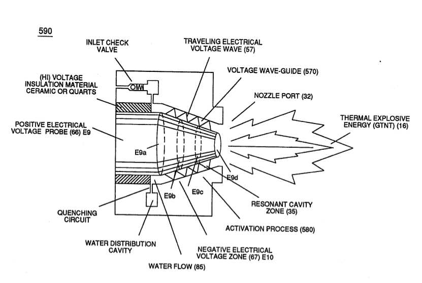](https://stanslegacy.com/uploads/images/gallery/2023-12/3rqyqz3Db9hi34S5-image-1702964855440-47-33.png) | (100) of Figure (4-8) [](https://stanslegacy.com/uploads/images/gallery/2023-12/0nCgQtWc7OEumvhA-image-1702697290149-28-07.png) |
| **Voltage Triggering Process** (70) of Figure (4-5) [](https://stanslegacy.com/uploads/images/gallery/2023-12/iQtzw2H4BR15Xg4c-image-1702697308683-28-25.png) | voltage intensifier coil-assembly (580) of Figure (6-1) [](https://stanslegacy.com/uploads/images/gallery/2023-12/d1D847vWWcde3rq2-image-1702964848304-47-25.png) |
| coil-structures (580) of Figure (6-1) [](https://stanslegacy.com/uploads/images/gallery/2023-12/d1D847vWWcde3rq2-image-1702964848304-47-25.png) | "**Voltage Intensity of Opposite Potential**" (600) of Figure (6-3) [](https://stanslegacy.com/uploads/images/gallery/2023-12/ae2fQLh3bxGLvcDD-image-1702612727504.png) |
| **Hydrogen Fracturing Process** (520) of Figure (5-3) [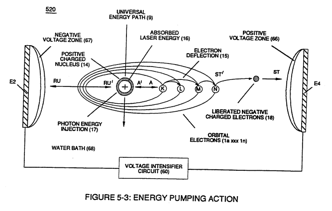](https://stanslegacy.com/uploads/images/gallery/2023-12/60fKlYumsAqhz4DV-image-1702942966128.png) | (100) of Figure (4-8) [](https://stanslegacy.com/uploads/images/gallery/2023-12/0nCgQtWc7OEumvhA-image-1702697290149-28-07.png) |
Resonant bobbin assembly (503), primary bobbin assembly (504), and secondary bobbin assembly (506), now, make up and structurally forms voltage intensifier (VIC) coil-assembly (530) of Figure (5-6) when electrical steel core material (53) forms a close-loop magnetic induction pathway centrally through and around (VIC) coil-assembly (530), as schematically illustrated in (190) of Figure (3-23) ([Memo WFC 422 DA](https://stanslegacy.com/books/the-birth-of-new-technology/chapter/wfc-422da-wfc-hydrogen-gas-management-system "WFC 422DA - WFC Hydrogen Gas Management System")).
| (VIC) coil-assembly (530) of Figure (5-6) [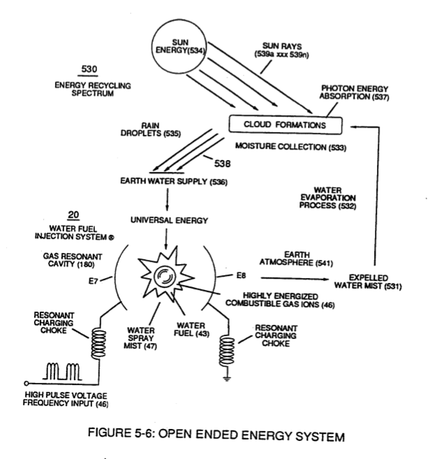](https://stanslegacy.com/uploads/images/gallery/2023-12/9GdRhTnMfsu7Uizv-image-1702959997026-26-33.png) | (190) of Figure (3-23) [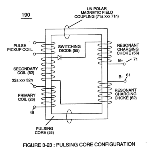](https://stanslegacy.com/uploads/images/gallery/2023-12/uvEuKjr24uvI4rUS-image-1702964648953-44-06.png) |
| [](https://stanslegacy.com/uploads/images/gallery/2023-12/d1D847vWWcde3rq2-image-1702964848304-47-25.png) | [](https://stanslegacy.com/uploads/images/gallery/2023-12/3rqyqz3Db9hi34S5-image-1702964855440-47-33.png) |
| [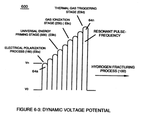](https://stanslegacy.com/uploads/images/gallery/2023-12/iwxpzwmKWYv1n1Gc-image-1702964864042-47-41.png) | [](https://stanslegacy.com/uploads/images/gallery/2023-12/Hx0R46fXOzjPFTPf-image-1702964870420-47-48.png) |
The **Voltage Intensifier Circuit** takes advantage of the "**Electron Bounce Phenomenon**" to trigger **Hydrogen Fracturing Process** without amp influxing.
[](https://stanslegacy.com/uploads/images/gallery/2023-12/bAVItVohodNi6mwc-image-1702446407451.png) Interlinked with VIC Coil Assembly, the Water Fuel Injector acts and performs as a "**Voltage Amplifier**" by simply altering the **Voltage Wave Guide** to either form a "**compressional**" or "**Expanded**" **Voltage Wave Form** that increases Electrical Voltage intensity beyond applied excitation voltage outputted from VIC Coil. The "Mode of Operability" of **VIC Coil Assembly** is systematically-activated by a programmable signal input, and is performed in the following way: Section 7 # Instant Explosion of Water The "mode-of-operability" of **VIC Coil Assembly** allows **Voltage Potential** of opposite voltage polarity to increase and be attenuated up to and beyond 20 Kilovolts while inhibiting and restricting amp leakage in the milliamperes range ... establishing operational parameter of utilizing "**Opposite Electrical Attraction Force**" of "high voltage intensity" to "instantly" releases thermal explosive energy (gtnt) from natural water.The **Voltage Intensifier Circuit** takes advantage of the "**Electron Bounce Phenomenon**" to trigger **Hydrogen Fracturing Process** without amp influxing. **Taper Resonant Cavity** functions as a "**Voltage Amplifier**" when interlinked with **VIC Circuit**.
**Voltage Intensifier Circuit** (60) of Figure (3-22) ([Memo WFC 422 DA](https://stanslegacy.com/books/the-birth-of-new-technology/chapter/wfc-422da-wfc-hydrogen-gas-management-system "WFC 422DA - WFC Hydrogen Gas Management System")) as to Figure (1-1) (Memo WFC 420) and **Voltage Intensifier Circuit** (620) of Figure (7-1) are specifically designed to restrict amp flow during **Programmable Pulsing Operations** (49a xxx 49n) but in different operational modes:| Voltage Intensifier Circuit (60) of Figure (3-22) [](https://stanslegacy.com/uploads/images/gallery/2023-12/qE3cQ0pxOpRPnR0h-image-1702450549031.png) | Figure (1-1) (Memo WFC 420) [](https://stanslegacy.com/uploads/images/gallery/2023-12/nE8xp40ioBIjm8vR-image-1702450578980.png) | Voltage Intensifier Circuit (620) of Figure (7-1) [](https://stanslegacy.com/uploads/images/gallery/2023-12/wKUrbHtXacnQw5dk-image-1702450606619.png) |
VIC voltage circuit (60) utilizes copper wire-wrap to form **Resonant Charging Chokes** (56/62) of Figure (3-22) in conjunction with **Switching Diode** (55) to encourage and make use of "**Electron Bounce**" phenomena (700) of Figure (7-9) to help promote **Step Charging Effect** (628) of Figure (7-7) by preventing electrical discharge of **Resonant Cavity** (140 - 170) since **Blocking Diode** functions as an "**Open**" switch during **Pulse Off-time**;
| (56/62) of Figure (3-22) [](https://stanslegacy.com/uploads/images/gallery/2023-12/KgR5GDTiDAVfMhQK-image-1702521326594.png) | (700) of Figure (7-9) [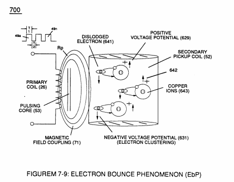](https://stanslegacy.com/uploads/images/gallery/2023-12/am1Vzd5M5NGGOdLw-image-1702521695880.png) |
| (628) of Figure (7-7) [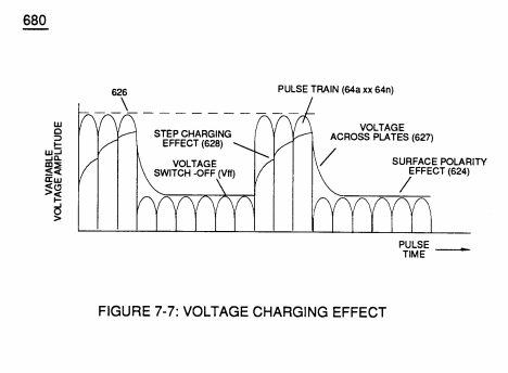](https://stanslegacy.com/uploads/images/gallery/2023-12/LoECA0KrkzgPKrsl-image-1702521680634.png) |
| (VIC - VB) (620) of Figure (7-1) [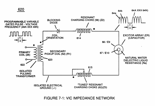](https://stanslegacy.com/uploads/images/gallery/2023-12/ZEMAYa97rz1qMSUW-image-1702521805142.png) | (616) of Figure (7-11) [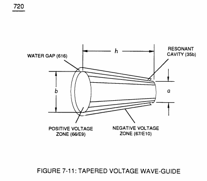](https://stanslegacy.com/uploads/images/gallery/2023-12/XgXLgArcunR7Ioqh-image-1702521824943.png) |
| (57 of Figure 3- 25 ~35 of Figure 6-2) [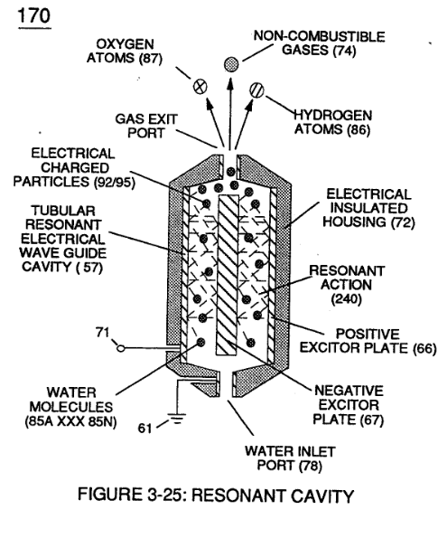](https://stanslegacy.com/uploads/images/gallery/2023-12/S3eCHXNW0INz4ErI-image-1702447512076.png) |
| (55) of Figure (3-22) [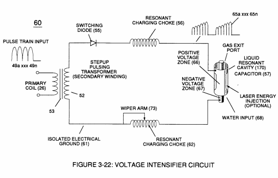](https://stanslegacy.com/uploads/images/gallery/2023-12/DUrWlUR26Hzb9DKq-image-1702521861249.png) | [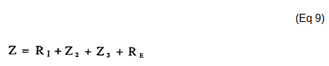](https://stanslegacy.com/uploads/images/gallery/2023-12/UbDtR88bFBhus4PS-image-1702446030322.png) |
| (T2) of Figure (7-8) [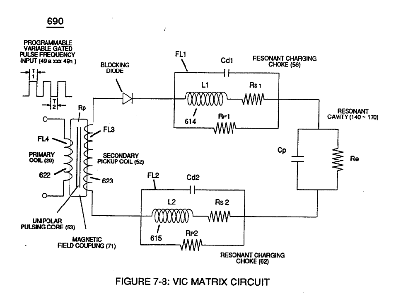](https://stanslegacy.com/uploads/images/gallery/2023-12/8RhgGnTT3BBYWsGx-image-1702447603158.png) |
... allowing the formation of an gated pulse-frequency pulse-train (64a/64b - T3 - 64a/64b) when pulse off-time (T3) is greater than time-period (T2)
... input-signal (49a xxx 49n) being a **Pulse-Train** where (T2) **pulse offtime** (T2) is adjusted to allow **Unipolar Pulse-Train** (64a xxx T3 xxx 64n)... outputting **Voltage-wave signal** (64a xxx 64n) being a pulse-frequency doubler due to **Inductance Reactance** (FL) of **Inductor Coil** (56) of Figure (3-22) when collapsing magnetic field (FL) of Figure (7-3b) re-cuts **coil-wrap** (Ll) during each pulse off-time (T2)
| (56) of Figure (3-22) [](https://stanslegacy.com/uploads/images/gallery/2023-12/DUrWlUR26Hzb9DKq-image-1702521861249.png) | (FI) of Figure (7-3b) [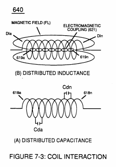](https://stanslegacy.com/uploads/images/gallery/2023-12/CiBOKjJUeggwHnqU-image-1702521915522.png) |
... producing a second **unipolar voltage wave-form** (64b) during the rise and fall of **magnetic field** (71), as further illustrated in (620) of Figure (7-1)
| (620) of Figure (7-1) [](https://stanslegacy.com/uploads/images/gallery/2023-12/ZEMAYa97rz1qMSUW-image-1702521805142.png) |
In reference to the use of **stainless steel (s/s) coil-wrap** (614/615), resistive wire value (Rs1/Rs2) of Figure (7-8) (typically 11.6K ohms per coil) is sufficient enough to inhibit current flow oscillation in direct relationship to circuit impedance (Eq. 9) since "current flow" is, also, restricted in the milliampere (s) range due to (s/s) wire material (Rs1/Rs2) composition ability to oppose electron interaction or electron interchange from one atomic structure to another;
| Figure (7-8) [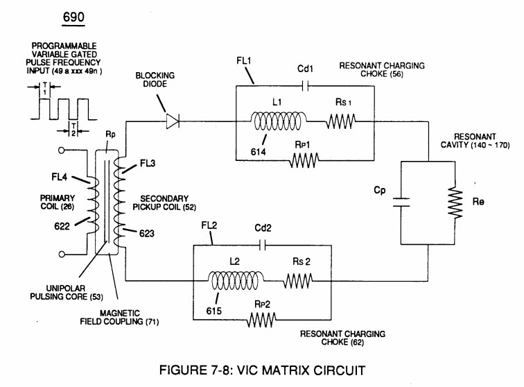](https://stanslegacy.com/uploads/images/gallery/2023-12/EcTw1oCYC89RtuRU-image-1702522773252.png) |
while, at the same time, conducting and permitting the transmission of "**Voltage Potential**" across circumference surface area (skin effect) (66/67) of Figure (7-11) as to Figure (590) of Figure (6-2) to bring-on and perform **Voltage Wave-Guide** phenomena (57) of Figure (6-2)
| (66/67) of Figure (7-11) [](https://stanslegacy.com/uploads/images/gallery/2023-12/XgXLgArcunR7Ioqh-image-1702521824943.png) | Figure (590 & 57) of Figure (6-2) [](https://stanslegacy.com/uploads/images/gallery/2023-12/yfkyykTD8kyZ0ZlP-image-1702321431762.png) |
| (390) of Figure (3-42) [](https://stanslegacy.com/uploads/images/gallery/2023-12/xtNJMfZF1nVcDD8O-image-1702522237864.png) |
... releasing thermal explosive energy (gtnt) (16) of Figure (4-5) on demand from natural water (85) of Figure (3-26) since the dielectric value (Re) of (Eq.9) of **Water Fuel** (85) is further approximated in **Capacitance Equation** (Eq.22), as illustrated in (650) of Figure (7-4) as to **Tapered Voltage Wave-Guide** (720) of Figure (7-11)
| (Eq.9) [](https://stanslegacy.com/uploads/images/gallery/2023-12/UbDtR88bFBhus4PS-image-1702446030322.png) | **Capacitance Equation** (Eq.22) [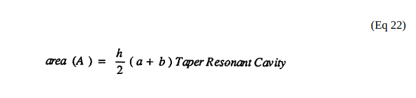](https://stanslegacy.com/uploads/images/gallery/2023-12/7DDADpHgskHekyV1-image-1702445610200.png) |
| (16) of Figure (4-5) [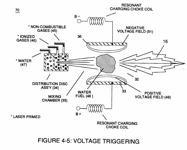](https://stanslegacy.com/uploads/images/gallery/2023-12/qUQHSp12cVcnBENa-image-1702522392526.png) | (85) of Figure (3-26) [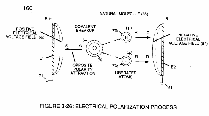](https://stanslegacy.com/uploads/images/gallery/2023-12/s1aNgyvbQfty0GCe-image-1702522414996.png) |
| (650) of Figure (7-4) [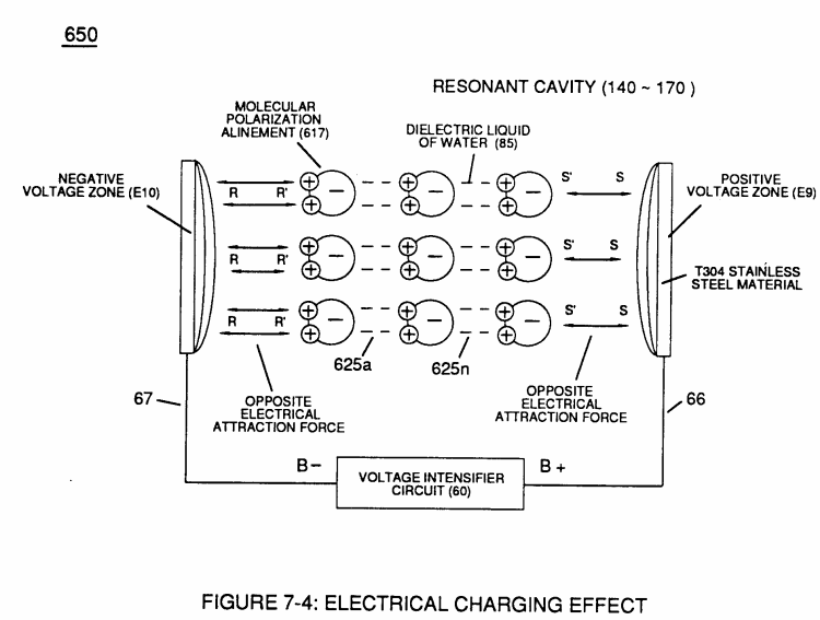](https://stanslegacy.com/uploads/images/gallery/2023-12/UoO5TLFZxfZ4cFMt-image-1702522441222.png) |
... allowing the dielectric value of **Water** (Re) to be a part of **Voltage Intensifier Circuit** (110) of Figure (4-9) capability of restricting amp flow during **Voltage Pulsing Operation** (49a xxx 49n) of (620) of Figure (7-1) as to **VIC Matrix Circuit** (690) of Figure (7-8)
| (110) of Figure (4-9) [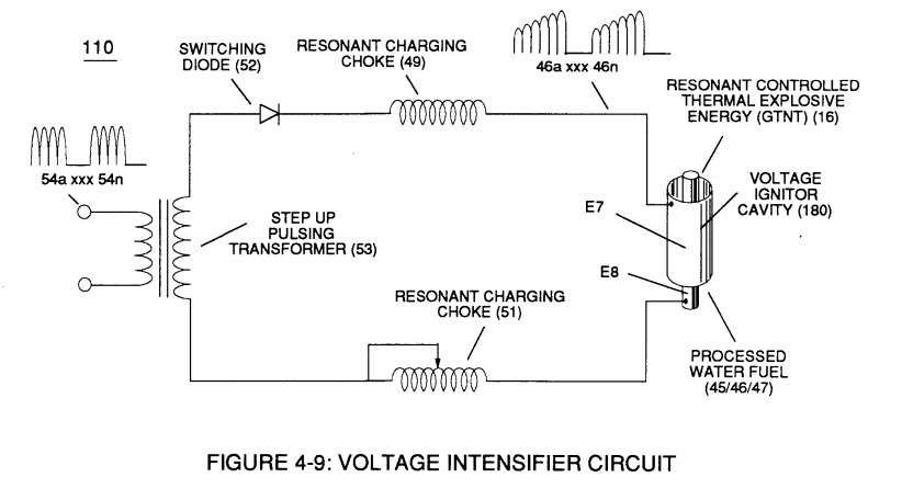](https://stanslegacy.com/uploads/images/gallery/2023-12/ZKdHcSrPTzqTGehg-image-1702522497308.png) | (620) of Figure (7-1) [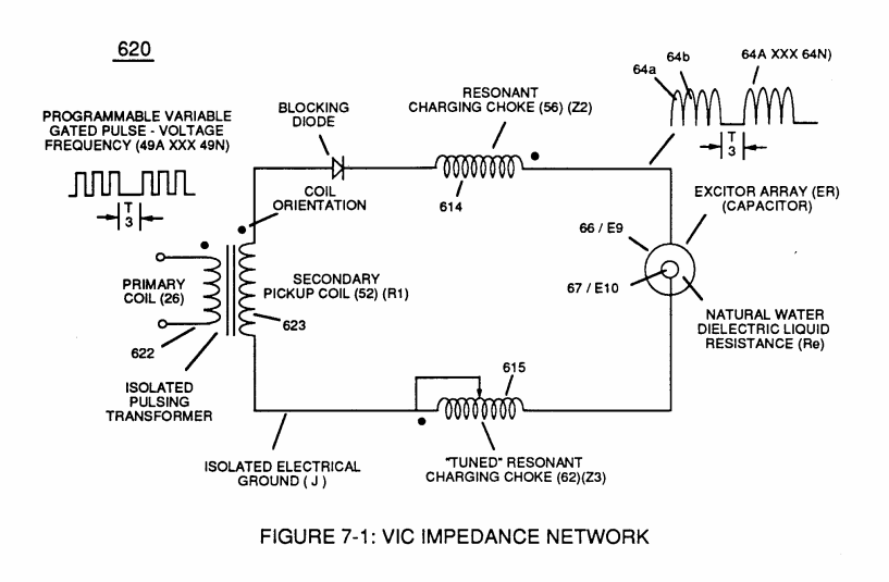](https://stanslegacy.com/uploads/images/gallery/2023-12/R1lOtNQx7TYKJE0K-image-1702522545833.png) | (690) of Figure (7-8) [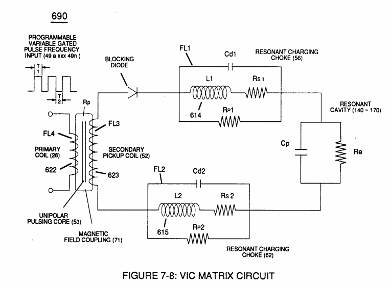](https://stanslegacy.com/uploads/images/gallery/2023-12/yHaOpfWt0J3UADOI-image-1702522535398.png) |
| Figure (7-13) [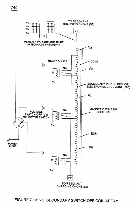](https://stanslegacy.com/uploads/images/gallery/2023-12/twi9EVhUdHC5iU2v-image-1702522907000.png) | (600) of Figure (6-3) [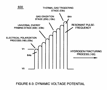](https://stanslegacy.com/uploads/images/gallery/2023-12/yR2ozomX4d6ZwF4Q-image-1702522927175.png) |
| (630) of Figure (7-2) [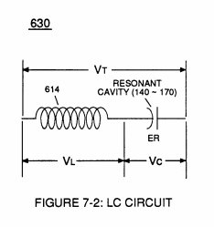](https://stanslegacy.com/uploads/images/gallery/2023-12/4sdqZG0IaZYnSlgA-image-1702522955010.png) | (614) of Figure (7-1) [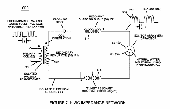](https://stanslegacy.com/uploads/images/gallery/2023-12/NBG7afC58ntC82uF-image-1702522964899.png) | (720) of Figure (7-11) [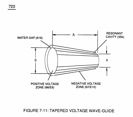](https://stanslegacy.com/uploads/images/gallery/2023-12/yhRkCX4nPiB5Jzre-image-1702522979960.png) |
| (580) of Figure (6-1) [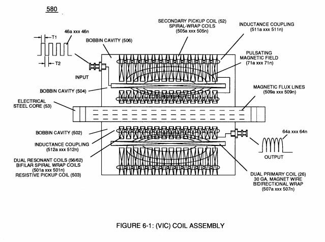](https://stanslegacy.com/uploads/images/gallery/2023-12/nQymCnRuuu9kwxZK-image-1702523026667.png) | (710) of Figure (7-10) [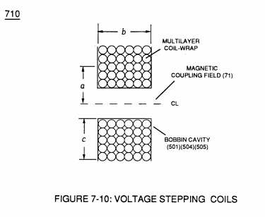](https://stanslegacy.com/uploads/images/gallery/2023-12/nWBMpPPEl3Kp8QLw-image-1702523048872.png) |
| (E9/E10 & 590) of figure (6-2) [](https://stanslegacy.com/uploads/images/gallery/2023-12/yfkyykTD8kyZ0ZlP-image-1702321431762.png) | (720, 616) of Figure (7-11) [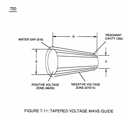](https://stanslegacy.com/uploads/images/gallery/2023-12/WDhQyKFykbXZqyE9-image-1702523112314.png) | (650) of Figure (7-4) [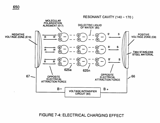](https://stanslegacy.com/uploads/images/gallery/2023-12/92eJFYnLb8CP2KCf-image-1702523165277.png) |
| (670) of Figure (7-6) [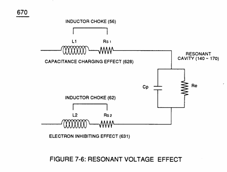](https://stanslegacy.com/uploads/images/gallery/2023-12/v9yvZKzZQoj22ijf-image-1702523182522.png) | (690) of Figure (7-8) [](https://stanslegacy.com/uploads/images/gallery/2023-12/mS1TJ8D4WchLcBMl-image-1702523192729.png) |
| **Inductor** (614) of Figure (7-1) [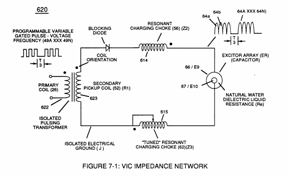](https://stanslegacy.com/uploads/images/gallery/2023-12/MzvPeyjbCL5eKKdo-image-1702523206210.png) | **Capacitor** (E9/E10) of Figure (7-11) [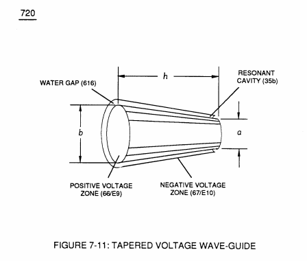](https://stanslegacy.com/uploads/images/gallery/2023-12/we95r1OtxtgObNm1-image-1702523235713.png) | LC circuit of Figure (7-2) [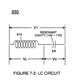](https://stanslegacy.com/uploads/images/gallery/2023-12/DJ53zhMs2MJCXMU1-image-1702523248932.png) |
| (600) of Figure (6-3) [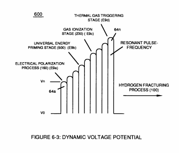](https://stanslegacy.com/uploads/images/gallery/2023-12/LnZPOrM8WkzklnDw-image-1702523261641.png) |
| Figure (7-3) [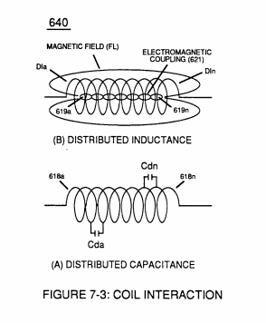](https://stanslegacy.com/uploads/images/gallery/2023-12/Vuwjy3nHVnRyKDxQ-image-1702523366857.png) | (614) of (7-1) [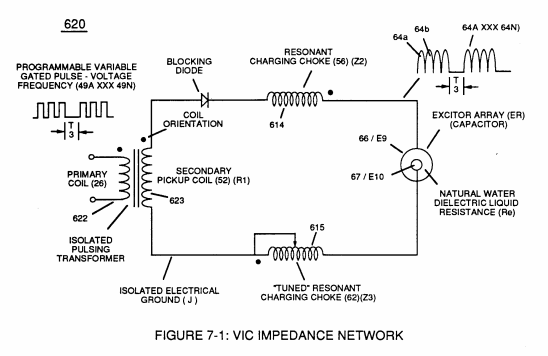](https://stanslegacy.com/uploads/images/gallery/2023-12/uOpq8b10Ve8tCGxN-image-1702523375710.png) |
| (210) of Figure (3-27) [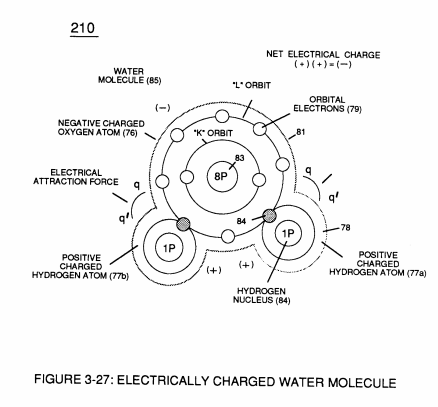](https://stanslegacy.com/uploads/images/gallery/2023-12/EaaeCiLWG4eF5IYO-image-1702523405268.png) |
Electron interaction (movement of electrons through the liquid medium of water) is further inhibited since natural water contaminates (144a xxx 144n) of Figure (3-24) is normally less than 20 ppm.
Figure (3-24) [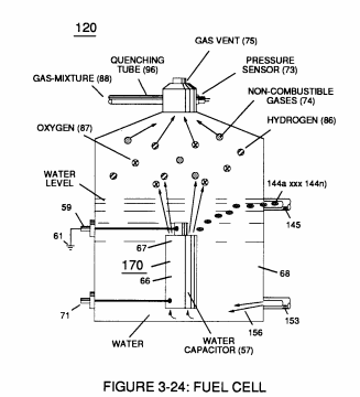](https://stanslegacy.com/uploads/images/gallery/2023-12/Kfu24EK7tggNsqf0-image-1702523475722.png)| (760) of Figure (7-15) [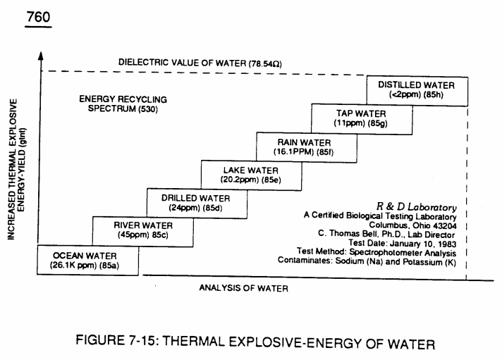](https://stanslegacy.com/uploads/images/gallery/2023-12/nkqNgBaOQsVb217Y-image-1702523547925.png) | (750) of Figure (7-14) [](https://stanslegacy.com/uploads/images/gallery/2023-12/xXYPbXntk7oyMnOD-image-1702523537999.png) |
... distilled water, of course, is generally lab-tested 1ppm or less, as illustrated in (760) of Figure (7-15) as to (750) of Figure (7-14).
# Capacitance (Cd) **Capacitor** (E9/E10) of Figure (7-1) as to Figure (650) of Figure (7-4) in direct relationship to **Water Gap** (616) becomes **Taper Resonant Cavity** (720) of Figure (7-11) as shown in (590) of Figure (6-2) since **Water Gap** (616) is occupied by a dielectric liquid (Re) as herein before identified as **natural water** (85) having no electrolyte added thereto| Figure (7-1) [](https://stanslegacy.com/uploads/images/gallery/2023-12/sLkFz4mURx82cBMH-image-1702698562791-49-19.png) | Figure (650) of Figure (7-4) [](https://stanslegacy.com/uploads/images/gallery/2023-12/b8mwkrkwdlWoaora-image-1702698571159-49-29.png) |
| (720) of Figure (7-11) [](https://stanslegacy.com/uploads/images/gallery/2023-12/8cv37eAtzQtWSpuN-image-1702698583636-49-40.png) | (590) of Figure (6-2) [](https://stanslegacy.com/uploads/images/gallery/2023-12/iDN6sNT4uVrN1k82-image-1702697335129-28-52.png) |
... generally **rain water** (85f) (750) of Figure (7-14) being almost free of contaminates due to **Water Evaporation Process** (532) of Figure (5-6) ... **rain water** (850 being an **liquid-insulator** that restricts the flow of amps
| (750) of Figure (7-14) [](https://stanslegacy.com/uploads/images/gallery/2023-12/rfrUXpva2VKUILHN-image-1702698598868-49-54.png) | (532) of Figure (5-6) [](https://stanslegacy.com/uploads/images/gallery/2023-12/79b8QE87ACWFdEZr-image-1702593862699.png) |
| (66/67) of Figure (7-1) [](https://stanslegacy.com/uploads/images/gallery/2023-12/sLkFz4mURx82cBMH-image-1702698562791-49-19.png) | (650) of Figure (7-4) [](https://stanslegacy.com/uploads/images/gallery/2023-12/b8mwkrkwdlWoaora-image-1702698571159-49-29.png) |
In like manner, the stainless steel (s/s) T304 material that forms **Voltage Zones** (E9/EI0) undergo **particle alignment** of its **atomic structure** within the atomic infrastructure of plate-material (E9/E10) when exposed to the same applied electrical voltage fields (66/67) after a pre-set time
... causing **molecular electrical movement** to occur within the surface-material (E9/EI0)
... which, after occurring, the newly formed **molecular electrical orientation** (625a xxx 625n) of Figure (7-4) remains in electrical atomic alignment after pulse off-time (T2) aiding the transference of voltage potential during pulse on-time (T1)
| Figure (7-4) [](https://stanslegacy.com/uploads/images/gallery/2023-12/b8mwkrkwdlWoaora-image-1702698571159-49-29.png) |
| (720) of Figure (7-11) [](https://stanslegacy.com/uploads/images/gallery/2023-12/8cv37eAtzQtWSpuN-image-1702698583636-49-40.png) | (650) of Figure (7-4) [](https://stanslegacy.com/uploads/images/gallery/2023-12/b8mwkrkwdlWoaora-image-1702698571159-49-29.png) |
| Figure (7-1) [](https://stanslegacy.com/uploads/images/gallery/2023-12/sLkFz4mURx82cBMH-image-1702698562791-49-19.png) | (590) of Figure (6-2) [](https://stanslegacy.com/uploads/images/gallery/2023-12/iDN6sNT4uVrN1k82-image-1702697335129-28-52.png) |
| (670) of Figure (7-6) [](https://stanslegacy.com/uploads/images/gallery/2023-12/HSAV63t6lHwoHa23-image-1702618781512-39-39.png) | (710) of Figure (7-10) [](https://stanslegacy.com/uploads/images/gallery/2023-12/ntlSL5wboAbusOLy-image-1702611619154.png) |
| Figure (7-3) as to (580) [](https://stanslegacy.com/uploads/images/gallery/2023-12/LlSOAj47IlZrQIQX-image-1702696921764-21-58.png) | (580) as to Figure (6-1) [](https://stanslegacy.com/uploads/images/gallery/2023-12/nQymCnRuuu9kwxZK-image-1702523026667.png) |
The circular-spiral turns of wire (forming parallel electrical surfaces) is separated by an **Insulated Dielectric Coating Material** which forms a series of capacitors (Cda xxx Cdn) when magnetic flux-lines (619a xxx 619n) produce **Electromagnetic Coupling Field** (621) during pulse on-time (T1), as illustrated in (640) of Figure (7-3) as to (690) of Figure (7-8).
| (640) of Figure (7-3) [](https://stanslegacy.com/uploads/images/gallery/2023-12/LlSOAj47IlZrQIQX-image-1702696921764-21-58.png) | (690) of Figure (7-8) [](https://stanslegacy.com/uploads/images/gallery/2023-12/rpg6jPD7jlYgCwQs-image-1702618749219-39-07.png) |
| (670) of Figure (7-6) [](https://stanslegacy.com/uploads/images/gallery/2023-12/rpg6jPD7jlYgCwQs-image-1702618749219-39-07.png) | (690) of Figure (7-8) [](https://stanslegacy.com/uploads/images/gallery/2023-12/pmOZtz5IJZzxP9rs-image-1702698415485-46-53.png) |
**Resonant Charging Chokes** (614/615) 430F/FR 36 AWG (.006) stainless steel (s/s) wire equals **60 micro ohms per centimeter**;
**Primary Coil** (622) 22 AWG (.028) copper wire equals 5.1933 ohms per pound weight;
**Secondary Pickup Coil** (623) 35 AWG (.007) copper wire equals 13K ohms per pound weight.
"**Pyre-ML**" trade name "**Himol**" polymer coating-material is used to impart thermal and mechanical resistance to the stainless steel (s/s) wire (614/615) coating; both magnet wire sizes (622/623) uses solderable **Nysol** (Polyurethane Nylon Jacket) insulation enamel coating as a electrical shield-material
... all dielectric coatings having an effective 3KV per mil dielectric value and formulated specifically to endure automotive temperature range from -40 C to 155 C.
# Inductance Reactance (Rs - Cd - FL) **Inductance Reactance** occurs when resistance (Rs), capacitance (Cd), and Inductance (FL) interacts together during D.C. Pulsing (49a xxx 49n), as schematically depicted in (690) of Figure (7-8).| (690) of Figure (7-8) [](https://stanslegacy.com/uploads/images/gallery/2023-12/khSj9LU20SsuNc7o-image-1702618448888-34-06.png) |
**Inductance Reactance** not only increases voltage across water-capacitor (ER) beyond applied **Voltage Potential** (626) of Figure (7-7) but, also, establishes "**Impedance Field**" (FL) across **Inductors** (L1-L2) of Figure (7-6) which acts and performs as **Resonant Charging Chokes** (614/615) of Figure (7-1) once placed on opposite side of capacitor (ER) forming **Resonant voltage Effect Circuit** (670) of Figure (7-6), as illustrated in (620) of Figure (7-1) as to (690) of Figure (7-8).
| **Voltage Potential** (626) of Figure (7-7) [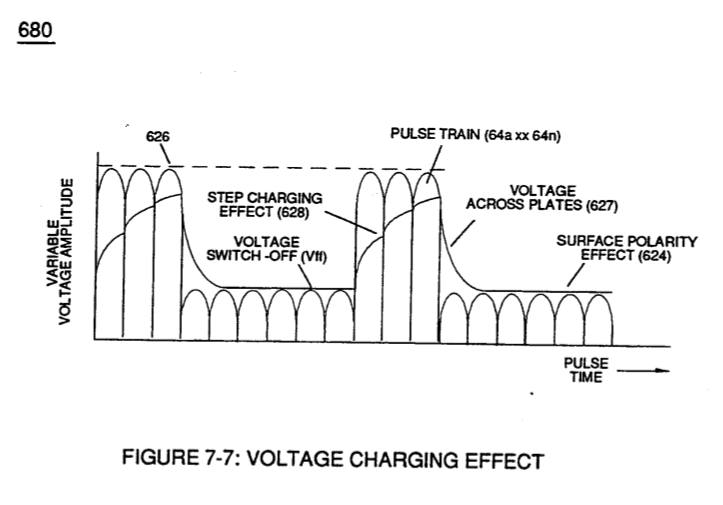](https://stanslegacy.com/uploads/images/gallery/2023-12/DxHHdQOGcn8xreEZ-image-1702618704743-38-22.png) | **Inductors** (L1-L2) of Figure (7-6) [](https://stanslegacy.com/uploads/images/gallery/2023-12/rpg6jPD7jlYgCwQs-image-1702618749219-39-07.png) |
| **Resonant Charging Chokes** (614/615) of Figure (7-1) [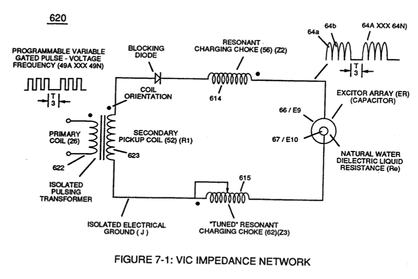](https://stanslegacy.com/uploads/images/gallery/2023-12/cGPbFx0DAuoueBNO-image-1702618762437-39-19.png) | (670) of Figure (7-6) [](https://stanslegacy.com/uploads/images/gallery/2023-12/HSAV63t6lHwoHa23-image-1702618781512-39-39.png) |
[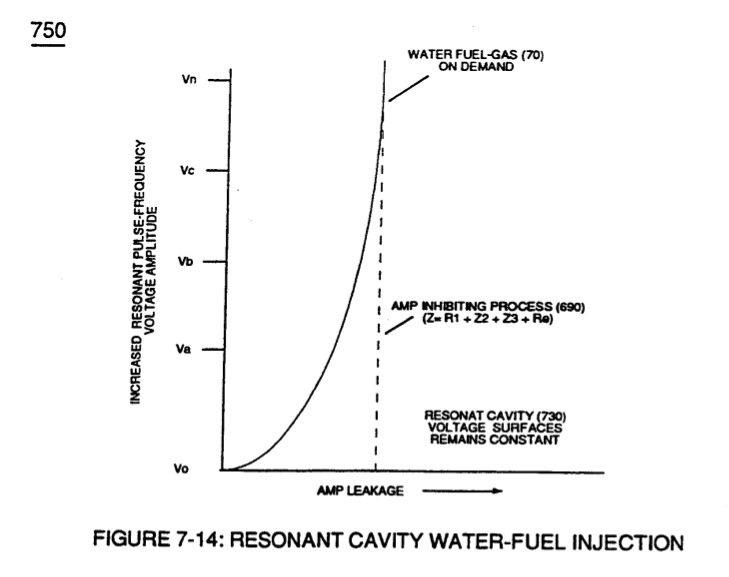](https://stanslegacy.com/uploads/images/gallery/2023-12/QIGKuhIZN7cxFl2A-image-1702618601495-36-35.png)Both Inductors (LI/L2) are Bifilar wound in equal length to **optimize the electromagnetic field strength** (FL) in equal electromagnetic intensity (FL1 = FL2) to encourage and promote "**Electron Bounce**" phenomenon (700) of Figure (7-9) while adjusting (programmable pulse wave-form) input signal **Pulse-Frequency** (49a xx 49n) to "tune-in" to the "dielectric property" (Re) of water (85) causing amp flow to be reduce to a minimum value while allowing voltage potential (627) of Figure (7-7) to go toward infinity if the electronic components would allow it to happen, as graphically illustrated in (750) of Figure (7-14).
| "**Electron Bounce**" phenomenon (700) of Figure (7-9) [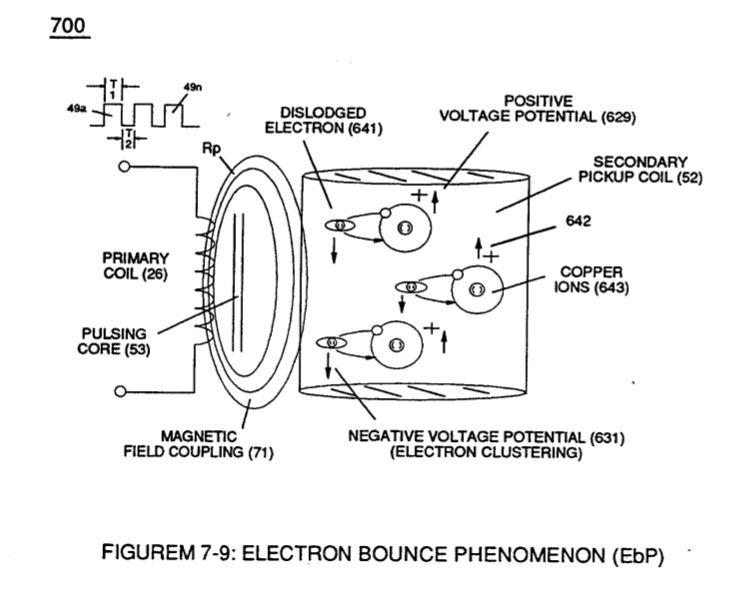](https://stanslegacy.com/uploads/images/gallery/2023-12/09D7i86bQoPuSMok-image-1702618687969-38-05.png) | (627) of Figure (7-7) [](https://stanslegacy.com/uploads/images/gallery/2023-12/DxHHdQOGcn8xreEZ-image-1702618704743-38-22.png) |
**Inductance Field** (L1-FL1) performs "**Capacitance Charging Effect**" (628);
while, at the same time, **Inductor Field** (L2-FL2) restricts electron movement through **VIC Impedance Network Circuit** (620) of Figure (7-1) since **Inductance Field** (FL2) locks onto **Electrons Magnetic Field** (547) of Figure (5-9) to block the movement of electron flow toward **Positive Voltage Potential** (66)| (620) of Figure (7-1) [](https://stanslegacy.com/uploads/images/gallery/2023-12/cGPbFx0DAuoueBNO-image-1702618762437-39-19.png) | (547) of Figure (5-9) [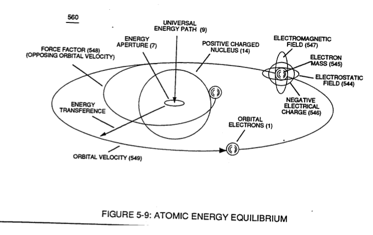](https://stanslegacy.com/uploads/images/gallery/2023-12/yTlTEfqjQueKixNq-image-1702619253236-47-30.png) *(This reference was incorrect. 647 mentioned, but 547 was desired - CB)* |
... thereby preventing and inhibiting electron-flow to pass through or arc-over capacitor water-gap (Cp) of Figure (7-8) such electron blocking action is herein called "**Electron Inhibiting Effect**" (631), as denoted in (670) of Figure (7-6) as to (750) of Figure (7-14).
| (Cp) of Figure (7-8) [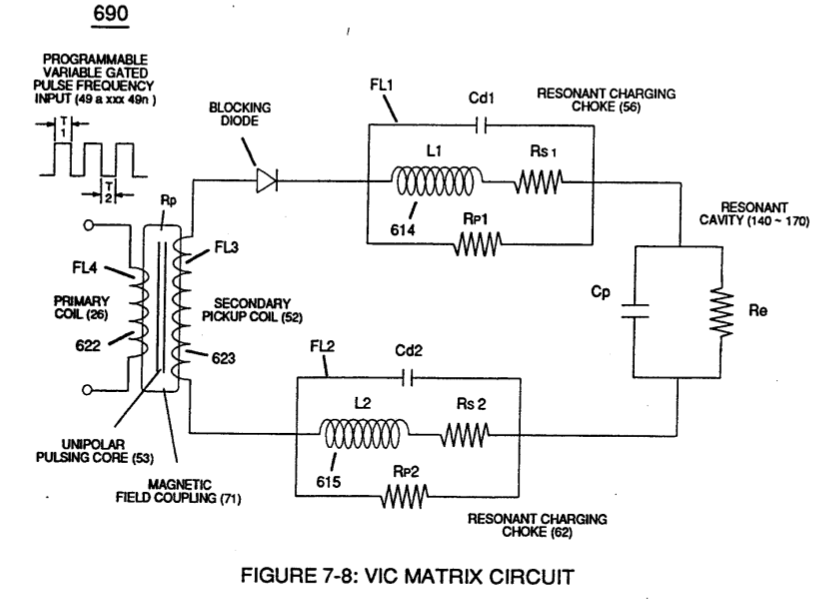](https://stanslegacy.com/uploads/images/gallery/2023-12/J6BescDSXykYRYy7-image-1702618809779-40-07.png) | (670) of Figure (7-6) [](https://stanslegacy.com/uploads/images/gallery/2023-12/HSAV63t6lHwoHa23-image-1702618781512-39-39.png) |
| (750) of Figure (7-14) [](https://stanslegacy.com/uploads/images/gallery/2023-12/QIGKuhIZN7cxFl2A-image-1702618601495-36-35.png) |
At elevated or higher amplitude voltage levels (xxx Ve xxx Vf xxx Vn), **primary electromagnetic coupling field** (Rp) of Figure (7-8) transmitted by way of **Inductance Pulsing-Core** (190) of Figure (3-23) as to **VIC Coil Assembly** (580) of Figure (6-1) enters into and passes through both Inductors (L1/L2) simultaneously and offers not only further electron-flow restriction (Rp1/Rp2) to both **Inductor Chokes** (56/62) but automatically increases voltage potential (xxx V g xxx Vh xxx Vn) of opposite voltage intensity of equal magnitude (66/67) across **Resonant Cavity** (140 -170)
| (Rp) of Figure (7-8) [](https://stanslegacy.com/uploads/images/gallery/2023-12/J6BescDSXykYRYy7-image-1702618809779-40-07.png) | **Inductance Pulsing-Core** (190) of Figure (3-23) [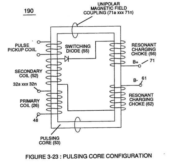](https://stanslegacy.com/uploads/images/gallery/2023-12/rPZwrTtoZvh5cReV-image-1702619947388-59-04.png) |
| **VIC Coil Assembly** (580) of Figure (6-1) [](https://stanslegacy.com/uploads/images/gallery/2023-12/nQymCnRuuu9kwxZK-image-1702523026667.png) |
**Electron Inhibiting Effect** (631) in direct relationship to **Voltage Enhancement Effect** (528) is accomplished since stainless steel 430F/FR wire-material is "**Electromagnetic Inductive**" to incoming electromagnetic flux-lines (71a xxx 71n) (Rp) without (s/s) inductor-wire-coil (L1/L2) becoming permanently magnetized
... paralleling and performing the same electromagnetic characteristic of copper wire when it comes to magnetic field reformation (Rp - Rp 1 - Rp2) of Figure (7-8), as further illustrated in electromagnetic coupling fields (71 - 511 - 512) of Figure (6-1) that encourages, brings-on, and perform **Voltage Inducement Process** (580) of Figure (6-1) as to (620) of Figure (7-1) without amp "influxing" (inhibiting amp flow) between **Positive Voltage Potential** (66) and **Negative Voltage Potential** (67) electrically applied across **Resonant Cavities** (140 -170).| Figure (7-8) [](https://stanslegacy.com/uploads/images/gallery/2023-12/J6BescDSXykYRYy7-image-1702618809779-40-07.png) | Figure (6-1) [](https://stanslegacy.com/uploads/images/gallery/2023-12/nQymCnRuuu9kwxZK-image-1702523026667.png) |
**Inductance Reactance** performs several functions simultaneously or to given stimuli:
- increases applied voltage amplitude (Vo - Vn) - doubles input frequency (64a \* 64b) when 50% Duty Cycle Pulse (T1 = T2) is inputted - effectuates "Step Charging Effect" (680) of Figure (7-7) when Pulse off-time (T2) is less than Pulse on-time (T1) ... determining **voltage swing** from **highest voltage level** (Vn) to **volts switch-off point** (Vff), and establishing **Impedance** (FL) which minimizes heat loss of electrical input power (49) by impairing electron movement.**Inductor** (Ll) acts and performs in like manner to **Inductor** (L2) since both **Inductor** (L1/L2) are physically the same size and shape.
**Thermal Explosive Energy-Yield** (gtnt) (16a xxx 16n) instantly produced from water (85) is determined by: - **Voltage Amplitude** ( xxx Vn) - **Duty Cycle of Pulse Train** (T1 - T2a xxx T1 – T2n) - **Gated Pulse-Frequency** of applied **Voltage Potential** (49a xxxx 49n - T3 - 49a xxx 49n) - **Inductor** (L1/L2) length - **Secondary Pickup Coil** (523) Length (FL3a xxx FL3n) - dielectric gap-spacing (Cp) - or any combination thereof. # Multi-layer Coil **Inductance** of a multi-layer coil of rectangular cross section can be computed by below formula when optimizing maximum distributed capacitance (Cda xxx Coo) and distributed inductance (Dla xxx Dln) of Figure (7-3) to intensify **Inductance Field Strength** (FLa xxx FLn) to function as a voltage multiplier in switch-off conditions (612a xxx 612n), as illustrated in (710) of ~ . Figure (7-10) as to **VIC Coil Assembly** (580) of Figure (6-1) and, is expressed:| Figure (7-3) [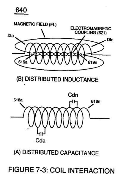](https://stanslegacy.com/uploads/images/gallery/2023-12/u1VHLAPCWpdV1nY5-image-1702611606686.png) | (710) of Figure (7-10) [](https://stanslegacy.com/uploads/images/gallery/2023-12/ntlSL5wboAbusOLy-image-1702611619154.png) |
| (580) of Figure (6-1) [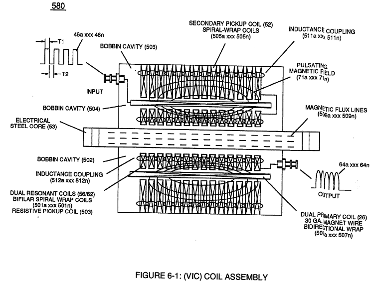](https://stanslegacy.com/uploads/images/gallery/2023-12/axyMmFebag8VQyKq-image-1702323131155.png) |
| (E1/E2) of Figure (1-1) page (1-13)[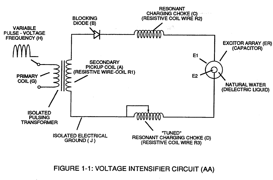](https://stanslegacy.com/uploads/images/gallery/2023-12/Ap7t402T7UGw9zDF-image-1702612009104.png) |
Stainless steel T304 material is used to form **Electrical Voltage-Plates** (EIIE2) which do "not" chemically interact (chemically inert) (Lab tested less than .0001/year decomposition rate) with liberated water gases (hydrogen \_86, oxygen \_87, and non-combustible gases W being exposed to an high intensity voltage pulse-field (64a xxx 64n) with negligible amp flow.
**Electrical Plates** herein called "**Excitor**" Plates or **Voltage Zones** (E1/E2) can take-on different configuration of shapes to maximize **Dynamic Voltage Potential** (600) of Figure (6-3) for different application of usage: (35a) **Traveling Constant Electrical Voltage Wave** by way of linear cylindrical resonant cavity (Tubular Cavity 730A), (35b) **Traveling Compressional** (concentrating electrical intensity) **Electrical Voltage Wave** by way of taper cylindrical resonant cavity (730B), (35c) **Traveling Expanding Electrical Voltage** wave by way of non-linear cylindrical resonant cavity (730C) ... or any voltage surface combination thereof ... each resonant cavity design acting and functioning as a **Voltage Wave-guide** (570) and gap-size (35) sufficient enough to allow the "**Quenching Effect**" to take place, as illustrated in (730) of Figure (7-12) as to (370) of Figure (3-40).| (730) of Figure (7-12) [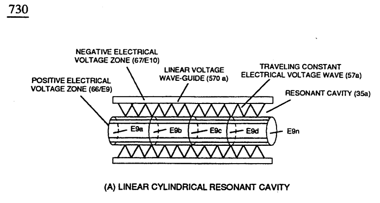](https://stanslegacy.com/uploads/images/gallery/2023-12/ZPYUzojeavXnoKig-image-1702612413679.png) | (370) of Figure (3-40) [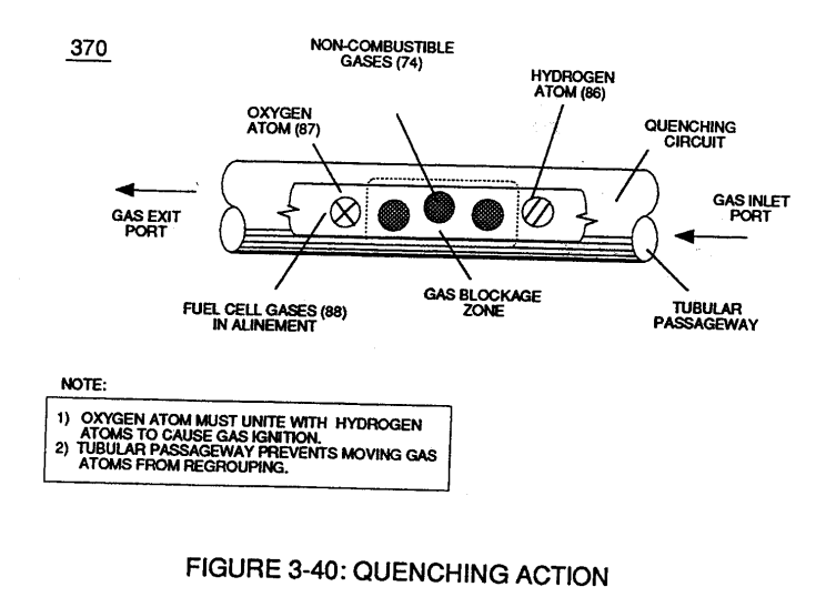](https://stanslegacy.com/uploads/images/gallery/2023-12/8G6ENOaauv9BUBR9-image-1702612439452.png) |
The dielectric property of water (being 78.54 ohms @ 25° C) permits the storage of '"**Electrical Charge**" when a potential voltage difference exists between **Electrical Voltage-Plates** (E1/E2) as to (E9/E10).
**[](https://stanslegacy.com/uploads/images/gallery/2023-12/FWz40QLyPOJwJefG-image-1702595701485.png)****Capacitance** (Cp) of Figure (7-6) as to (690) of Figure (7-8) is determined by the surface area (A) of **Electrical Voltage-Plates** (E1/E2 - E9/E10), the distance (d) between the **Electrical Plates** (in inches), and the **permittivity** (Eo) of the dielectric property of water (85) and, is expressed in the following equation:
| [](https://stanslegacy.com/uploads/images/gallery/2023-12/ArT7RvyVdVO2EISt-image-1702445844755.png) | (690) of Figure (7-8) [](https://stanslegacy.com/uploads/images/gallery/2023-12/gzGVEsezx0gmvk9h-image-1702612335114.png) |
| diagram 720 of Figure 7-11 [](https://stanslegacy.com/uploads/images/gallery/2023-12/nZspZRIZeJzET3th-image-1702612195058.png) |
**Capacitance Reactance** is determined by the insulation resistance (Rs+Re) and **Inductance** (L1/L2) interacting together during D.C. Pulsing.
Dielectric property of water opposes amp leakage (Re) while another property of water takes-on an "**Electrical Charge**". Water temperature (Rt) (cool-to-the-touch) keeps (Re) constant since amp flow remains minimal.**Plate Inductance** (Lc) is **Inductance Reactance** of **Inductor** (L1 ) and **Inductance Reactance** of **Inductor** (L2) in series with **Resonant Capacitor** (140 -170) of Figure (7-6) as to (690) of Figure (7-8).
| **Resonant Capacitor** (140 -170) of Figure (7-6) [](https://stanslegacy.com/uploads/images/gallery/2023-12/9aPfvETrheVTgOak-image-1702613092794.png) | (690) of Figure (7-8) [](https://stanslegacy.com/uploads/images/gallery/2023-12/gzGVEsezx0gmvk9h-image-1702612335114.png) |
In terms of **Component Reactance**, Inductors (L1/L2) should always be larger than **Capacitor** (ER) of Figure (7-2) in order to maximize amp restriction to enhance "**Voltage Deflection**" (SS' - 617a xxx 617n - RR') of Figure (7-4) and, is expressed by :
| **Capacitor** (ER) of Figure (7-2) [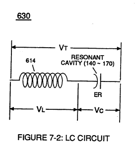](https://stanslegacy.com/uploads/images/gallery/2023-12/ld2UDKOKxvKptiGw-image-1702613172661.png) | "**Voltage Deflection**" of Figure (7-4) [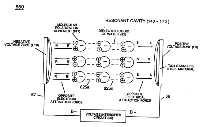](https://stanslegacy.com/uploads/images/gallery/2023-12/Dk0i0rZslFjtQ0mh-image-1702613196411.png) |
**Capacitor** (ER) should remain relatively small due to the dielectric value of water to obtain maximum **Thermal Explosive Energy-Yield** (16a xxx 16n) of Figure (4-5) and subsequently establishing **Quenching Circuit** (370) of Figure (3-40) to prevent gas ignition inside traveling voltage wave-guide (590) of Figure (6-2) as to (730) of Figure (7-12)
| **Quenching Circuit** (370) of Figure (3-40) [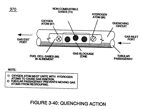](https://stanslegacy.com/uploads/images/gallery/2023-12/6YdTq2g8mdXowsG1-image-1702612910404.png) | (590) of Figure (6-2) [](https://stanslegacy.com/uploads/images/gallery/2023-12/yfkyykTD8kyZ0ZlP-image-1702321431762.png) | (730) of Figure (7-12) [](https://stanslegacy.com/uploads/images/gallery/2023-12/ZPYUzojeavXnoKig-image-1702612413679.png) |
| (390) of Figure (3-42) [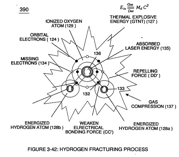](https://stanslegacy.com/uploads/images/gallery/2023-12/TQFB0ZhM8nvkNmk9-image-1702612844870.png) | (100) of Figure (4-8) [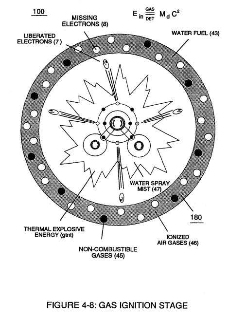](https://stanslegacy.com/uploads/images/gallery/2023-12/a4Go0D1jgDLn3L5B-image-1702612828723.png) |
... activating Voltage Ignition Process (90) of Figure (5-5)
| (90) of Figure (5-5) [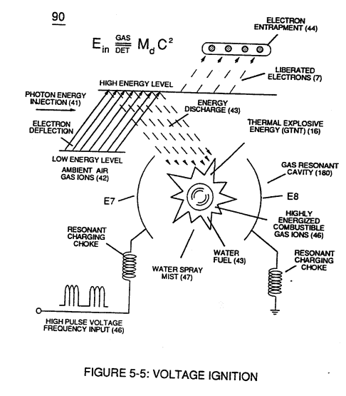](https://stanslegacy.com/uploads/images/gallery/2023-12/nRD1lRt7uMtzofTn-image-1702612762308.png) |
... utilizing **Dynamic Voltage Potential** (600) of Figure (6-3) of opposite electrical stress (SS' - 617 - RR') to cause **thermal atomic agitation** (90) of Figure (4-7) (kinetic heat by atomic motion)
| (600) of Figure (6-3) [](https://stanslegacy.com/uploads/images/gallery/2023-12/ae2fQLh3bxGLvcDD-image-1702612727504.png) | (90) of Figure (4-7) [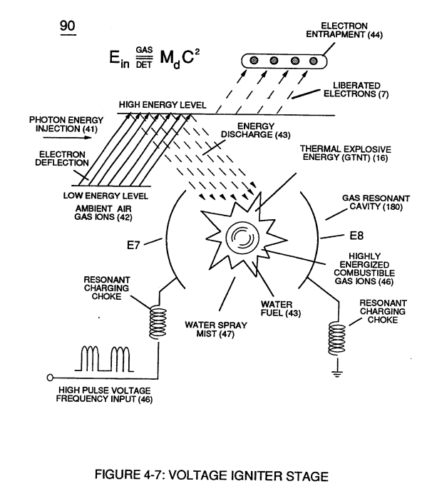](https://stanslegacy.com/uploads/images/gallery/2023-12/6foWfMiQi1c69WJT-image-1702612705935.png) |
| Figure (4-5) [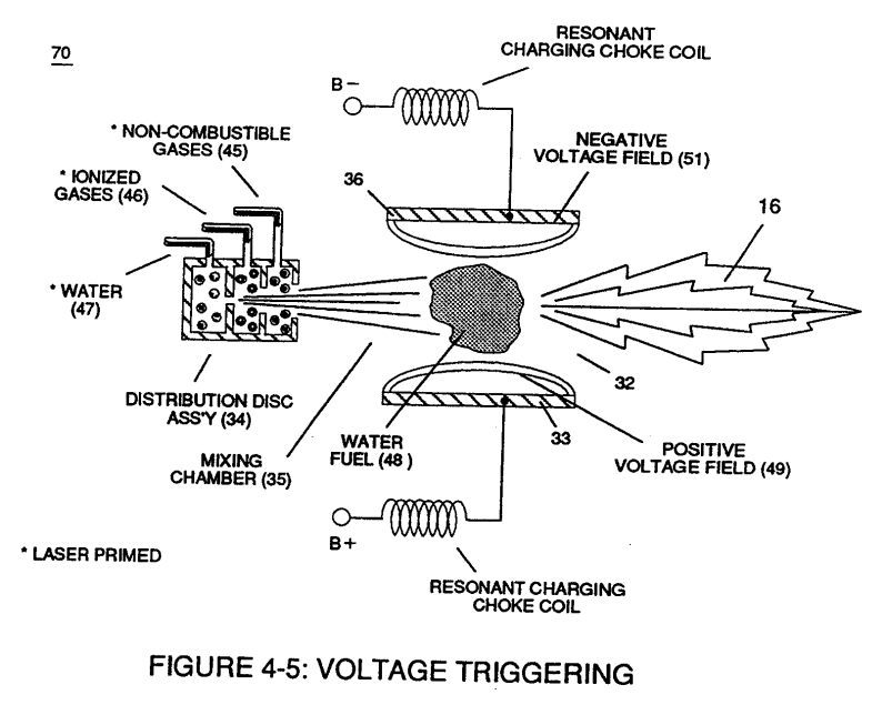](https://stanslegacy.com/uploads/images/gallery/2023-12/hdx8RZFks4JlKeUt-image-1702612666662.png) |
Total VIC "**Circuit Resistance**" to D.C. current flow is expressed and determined by:
[](https://stanslegacy.com/uploads/images/gallery/2023-12/UbDtR88bFBhus4PS-image-1702446030322.png) **Where**, (Rl) is the resistive value of **Secondary Pickup Coil** (52) of Figure (7-8) plus **Magnetic Field** strength of **primary coupling field** (71) in direct relationship to **inductance field strength** (Rp) which is determined by the number of turns of wire that make up secondary coil-wrap (52),| (52) of Figure (7-8) [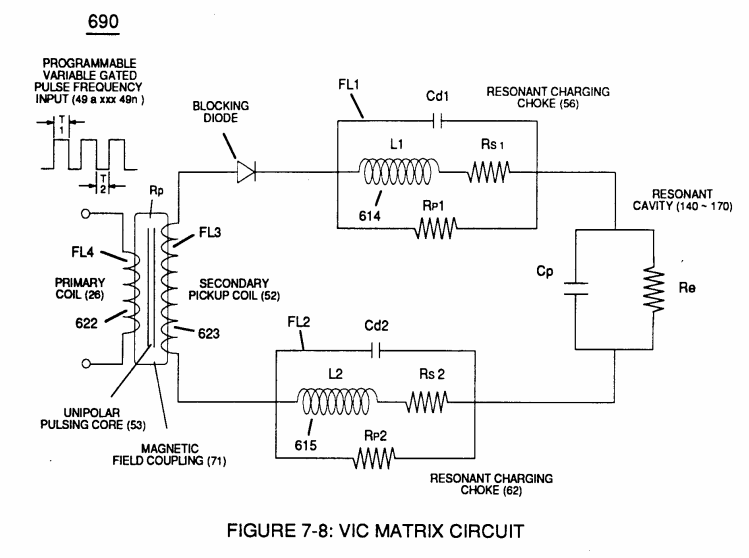](https://stanslegacy.com/uploads/images/gallery/2023-12/buC0CBJSdthSkou3-image-1702593978530.png) |
... each choke-coil (LIIL2) being of the same impedance value since both coil-wraps (56/62) are Bifilar wound together onto a single **spool-bobbin**, (Re) is the dielectric property of water and it's resistive value is typically (78.54 Q) since "**rain water**" (85f) contains less than 20ppm of any type of contaminates due to **Water Evaporation Process** (530) of Figure (5-6).
| (530) of Figure (5-6)  |
see **VIC Matrix Circuit** 690 of Figure 7-8 as to **Water Chan** (760) of Figure (7-15), once again
| 690 of Figure 7-8 [](https://stanslegacy.com/uploads/images/gallery/2023-12/buC0CBJSdthSkou3-image-1702593978530.png) | (760) of Figure (7-15) [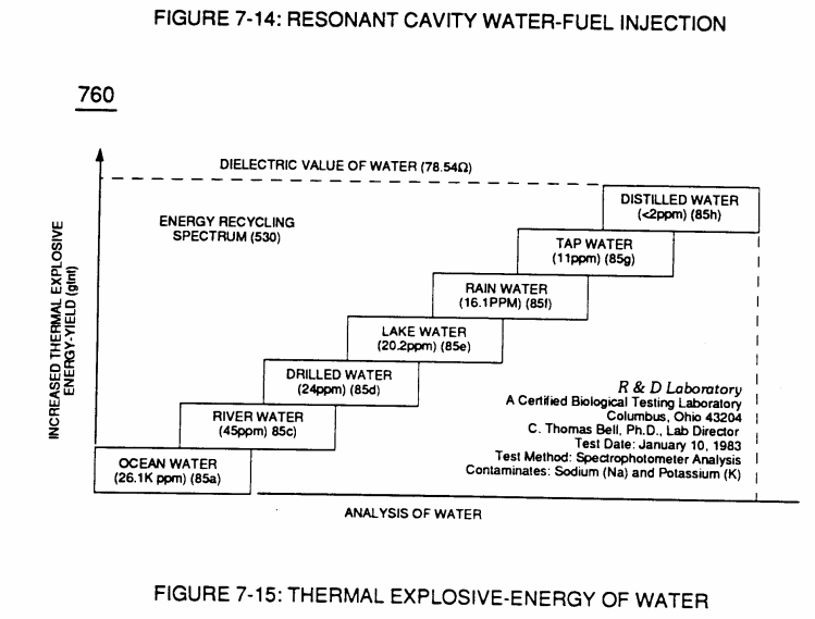](https://stanslegacy.com/uploads/images/gallery/2023-12/9S1FCBR2jNIa7VXs-image-1702594000864.png) |
| (53) of Figure (6-1) [](https://stanslegacy.com/uploads/images/gallery/2023-12/nQymCnRuuu9kwxZK-image-1702523026667.png) | (71) of Figure (7-8) [](https://stanslegacy.com/uploads/images/gallery/2023-12/buC0CBJSdthSkou3-image-1702593978530.png) |
The turns ratio of the **VIC Transformer** (26/52) is determined by the following equation:
[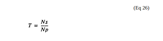](https://stanslegacy.com/uploads/images/gallery/2023-12/0FfSa2XjWgyWvDtp-image-1702446102303.png) **Where**,(Ns) is the number of turns of wire for each bobbin cavity (505) of Figure (6-1) as to (710) of Figure (7-10) that are electrically connected in series arrangement (505a xxx 505n) to form **Secondary** **Coil-Wrap** (52),
| (505) of Figure (6-1) [](https://stanslegacy.com/uploads/images/gallery/2023-12/nQymCnRuuu9kwxZK-image-1702523026667.png) | (710) of Figure (7-10) [](https://stanslegacy.com/uploads/images/gallery/2023-12/nWBMpPPEl3Kp8QLw-image-1702523048872.png) |
[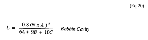](https://stanslegacy.com/uploads/images/gallery/2023-12/lQrzUXSnbY5rtQb2-image-1702595344873.png)... each bobbin cavity adhering to equation (Eq 20), as illustrated in (710) of Figure (7-10).
| (505) of Figure (6-1) [](https://stanslegacy.com/uploads/images/gallery/2023-12/nQymCnRuuu9kwxZK-image-1702523026667.png) | (710) of Figure (7-10) [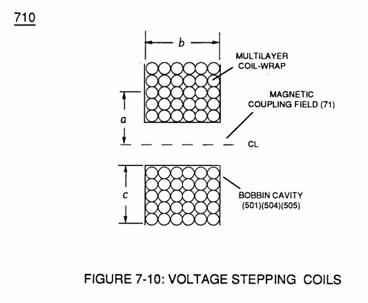](https://stanslegacy.com/uploads/images/gallery/2023-12/n5MlacxPndMbnvcR-image-1702594471767.png) |
The **impedance ratio** of VIC transformer is determined by:
[](https://stanslegacy.com/uploads/images/gallery/2023-12/d2LspWrLSsIZZ8i0-image-1702446118191.png) **Where**, (1'2) is the sum of the magnetic field strength (FL4) of the **primary coil** (26) and the **induced magnetic field** (FL3) of the **Secondary Pickup Coil** (52) during each pulse cycle (T1) in direct relationship to repetitive pulse cycling (T1a xxx T1n) and both magnetic fields (FL3/FL4) interacting, and is expressed in the following equation: [](https://stanslegacy.com/uploads/images/gallery/2023-12/2BG3s0gDGp33Yygq-image-1702446130639.png) **Where**, (M) is the mutual inductance expressed in the same units .as (La), (La) is the total inductance of **Primary coil** (26) and Secondary coil (52) with fields aiding **Coupling Inductance** (Rp) between the **Primary coil** (26) and **Secondary Coil** (52) is further extrapolated in the following equation: [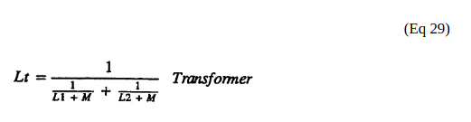](https://stanslegacy.com/uploads/images/gallery/2023-12/cT0wusDcHXsvGdp5-image-1702446153461.png) **Where**, (Lt) is the total inductance, (L1) and L2) are the inductances of each individual transformer coils (26)(52), (M) is the mutual inductance of each transformer coil (26/52) being in parallel relationship with fields aiding **Coupling Inductance** (Rp1) and (Rp2) in (690) of Figure (7-8) is further expressed in the following equation: [](https://stanslegacy.com/uploads/images/gallery/2023-12/Eyi5pwuUvYxixdvm-image-1702446178855.png) **Where**, (Lt cc) is the total inductance of **Choke Coils** (FL1 - FL2), (L1) and (L2) are the inductances of each individual choke coil (56)(62) in series with **Secondary Coil** (52) **Electrical Voltage** **Potential** (700) of Figure (7-9) and being exposed to the same **Voltage Transformer** (26 - 53 - 52) magnetic field (Rp) with aiding fields, (M) is the mutual inductance of choke coils (L1/L2) since **Transformer Magnetic Field** (Rp) is the excitation **External Magnetic Field** (Rp1/Rp2) by way of **Unipolar Pulsing Core** (53).**VIC Coil Assembly** (580) of Figure (6-1) as to (690) of Figure (7-8) in reference to **Schematic Circuit** (620) of Figure (7-1) is constructed in such a way as to rotate and position **Inductor Coils** (26 - 52 - 56 - 62) to be of the same electromagnetic polarity orientation, indicator mark (e)
| (580) of Figure (6-1) [](https://stanslegacy.com/uploads/images/gallery/2023-12/nQymCnRuuu9kwxZK-image-1702523026667.png) | (690) of Figure (7-8) [](https://stanslegacy.com/uploads/images/gallery/2023-12/buC0CBJSdthSkou3-image-1702593978530.png) |
| **Inductance Charging Effect** (660) of Figure (7-5) [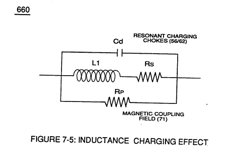](https://stanslegacy.com/uploads/images/gallery/2023-12/OJ4oQWHq5REb8uVE-image-1702595636154.png) | **Resonant Voltage Effect** (670) of Figure (7-6) [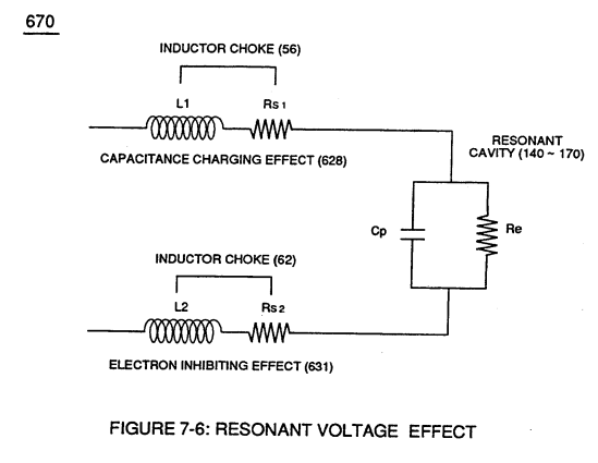](https://stanslegacy.com/uploads/images/gallery/2023-12/F8SiHklu1rTCr0kf-image-1702595646541.png) |
| (547) of Figure (5-9) [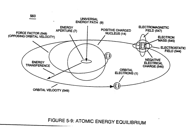](https://stanslegacy.com/uploads/images/gallery/2023-12/VTmtI7b0eETTHgBj-image-1702595664580.png) | **(700) of Figure (7-9)** [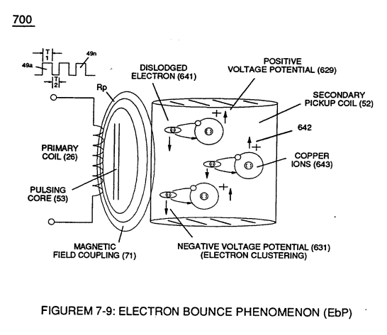](https://stanslegacy.com/uploads/images/gallery/2023-12/SIOmTh50yR29ICJg-image-1702595681532.png) |
| **Electron Inhibiting Effect** (631) of Figure (7-6) [](https://stanslegacy.com/uploads/images/gallery/2023-12/FWz40QLyPOJwJefG-image-1702595701485.png) | "**Electron Clustering**" (Grouping/collecting negative charged particles at a given point) (700) of Figure (7-9) [](https://stanslegacy.com/uploads/images/gallery/2023-12/SIOmTh50yR29ICJg-image-1702595681532.png) |
| **''Negative Voltage Potential"** ( B- ) at one side of Water Gap (Cp) of Figure (7-8) & magnetic field (FL2) (690) of Figure (7-8) [](https://stanslegacy.com/uploads/images/gallery/2023-12/buC0CBJSdthSkou3-image-1702593978530.png) | **Choke-Coil** (62) of Figure (7-1) [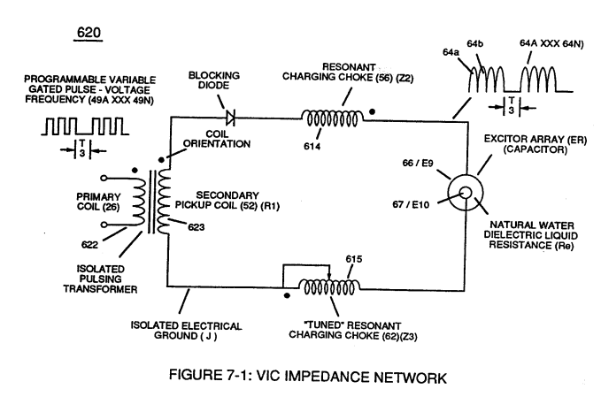](https://stanslegacy.com/uploads/images/gallery/2023-12/ZpW3wOEzH7FjjjUD-image-1702595741313.png) |
.... causing **mutual inductance** (μ1) (*see equations Eq 28 thru Eq 30*) to transform **Distributed Capacitance** (Cda xxx Cdn) of Figure (7-3) of each **inductance coils** (52 - 56 - 62) into a coherent **Voltage Potential** (Yo •..• Vn) equaling the sum of **Voltage Potential** (Vp) developed across each **Pickup Coils** (VpT + Vp1 + Vp2)
| **Distributed Capacitance** (Cda xxx Cdn) of Figure (7-3) [](https://stanslegacy.com/uploads/images/gallery/2023-12/LlSOAj47IlZrQIQX-image-1702696921764-21-58.png)[](https://stanslegacy.com/uploads/images/gallery/2023-12/LnZPOrM8WkzklnDw-image-1702523261641.png) | equations Eq 28 thru Eq 30
Where, (M) is the **mutual inductance** expressed in the same units as (La), (La) is the total inductance of **Primary coil** (26) and **Secondary coil** (52) with fields aiding. [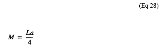](https://stanslegacy.com/uploads/images/gallery/2023-12/orOnPIsU3RdG7LrS-image-1702697017447-23-35.png)**Coupling Inductance** (Rp) between the **Primary coil** (26) and **Secondary Coil** (52) is further extrapolated in the following equation: Where, (Lt) is the **total inductance**, (L1) and L2) are the **inductance** of each individual **transformer coils** (26)(52), (M) is the **mutual inductance** of each **transformer coil** (26/52) being in parallel relationship with fields aiding. [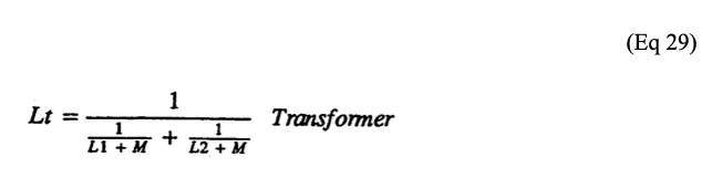](https://stanslegacy.com/uploads/images/gallery/2023-12/T3328JE66oBu2knt-image-1702697029338-23-46.png)**Coupling Inductance** (Rp1) and (Rp2) in (690) of Figure (7-8) is further expressed in the following equation: Where, (Lt cc) is the total inductance of **Choke Coils** (FL1 - FL2), (L1) and (L2) are the **inductance** of each individual **choke coil** (56)(62) in series with **Secondary Coil** (52) **Electrical Voltage Potential** (700) of Figure (7-9) and being exposed to the same **Voltage Transformer** (26 - 53 - 52) **magnetic field** (Rp) with aiding fields, (M) is the **mutual inductance** of **choke coils** (L1/L2) since **Transformer Magnetic Field** (Rp) is the **excitation External Magnetic Field** (Rp1/Rp2) by way of **Unipolar Pulsing Core** (53). [](https://stanslegacy.com/uploads/images/gallery/2023-12/eVVovbgNmXNPgC3a-image-1702697038796-23-56.png) |
... producing **Dynamic Voltage Potential** (600) of Figure (6-3) during repetitive pulsing (49a xxx 49n - T3 - 49a xxx 49n)
... setting up and performing pulsating **Opposite Electrical Attraction Force** (SS' ~ 617 ~ RR' - T3 - SS' ~ 617 - RR') of Figure (7-4) as to **Voltage Dynamics** (220) of Figure (3-29)| **Opposite Electrical Attraction Force** (SS' ~ 617 ~ RR' - T3 - SS' ~ 617 - RR') of Figure (7-4) [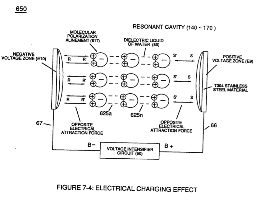](https://stanslegacy.com/uploads/images/gallery/2023-12/30kdftr7xeAN9f0p-image-1702697128032-25-25.png) | **Voltage Dynamics** (220) of Figure (3-29) [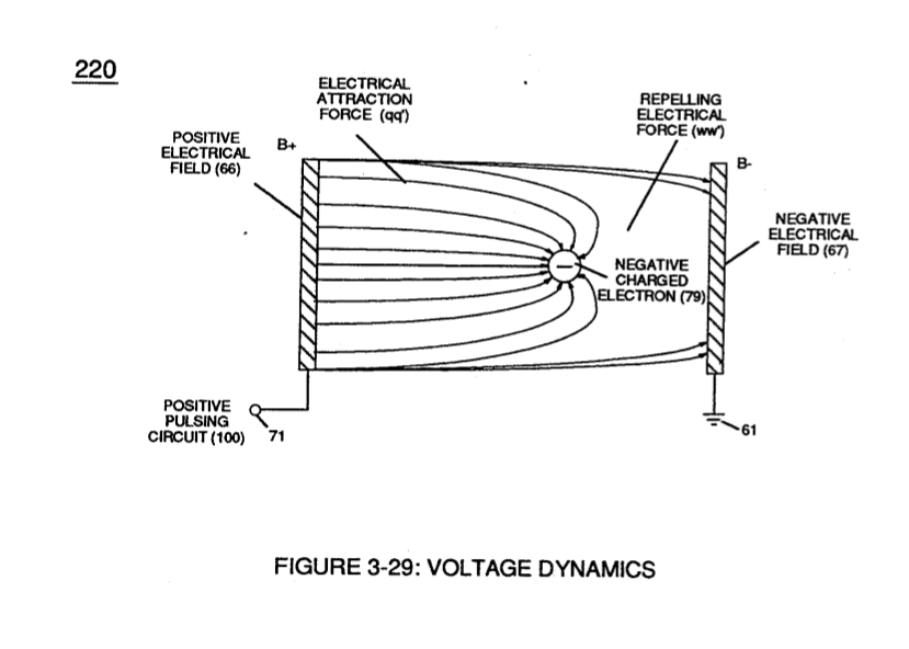](https://stanslegacy.com/uploads/images/gallery/2023-12/61XrnbO4fpkdykfp-image-1702697168227-26-06.png) |
| **Hydrogen Fracturing Process** (90) of Figure (5-5) [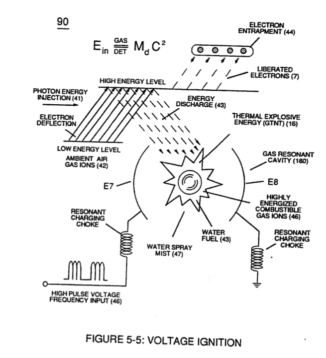](https://stanslegacy.com/uploads/images/gallery/2023-12/P3Y0jSKB2UWLLZWY-image-1702697249097-27-25.png) | (100) of Figure (4-8) [](https://stanslegacy.com/uploads/images/gallery/2023-12/0nCgQtWc7OEumvhA-image-1702697290149-28-07.png) |
| **Taper Resonant Cavity (590) of Figure (6-2)** [](https://stanslegacy.com/uploads/images/gallery/2023-12/iDN6sNT4uVrN1k82-image-1702697335129-28-52.png) | (70) of Figure (4-5) [](https://stanslegacy.com/uploads/images/gallery/2023-12/iQtzw2H4BR15Xg4c-image-1702697308683-28-25.png) |
... allowing, **Voltage Bounce Phenomenon** (700) of Figure (7-9) to be preformed.
| (700) of Figure (7-9) [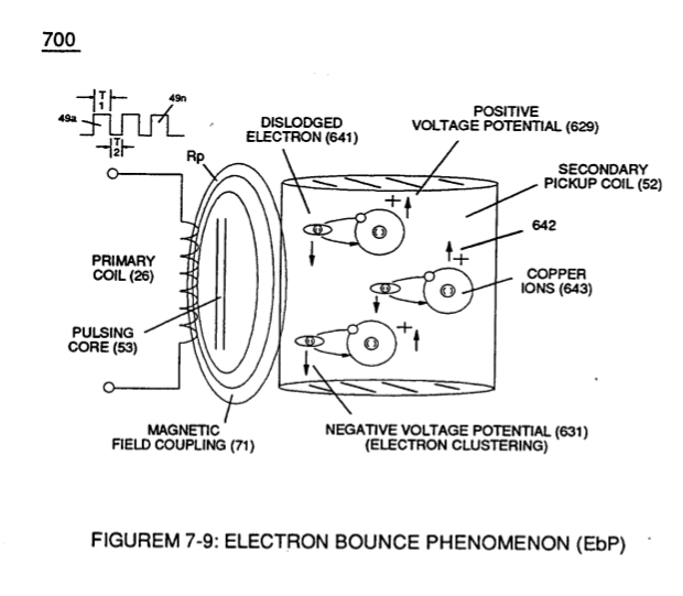](https://stanslegacy.com/uploads/images/gallery/2023-12/UY23IAmhCvdRkbPE-image-1702696671415-17-49.png) |
| (52) of Figure (7-8) [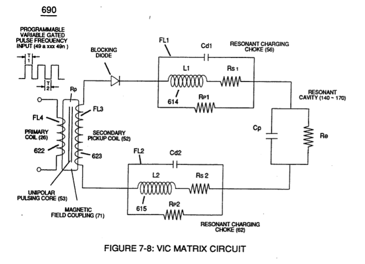](https://stanslegacy.com/uploads/images/gallery/2023-12/yzS6lTm0vWvVpwsS-image-1702696629185-17-03.png) |
Collectively, the resultant **positive electrical charged copper ions** (642a xxx 642n) added together produces **Positive Voltage Potential** (629) being electrically applied to **choke-coil** (56);
whereas, the "Liberated" **negative electrical charged electrons** (641a xxx 641n) added together provides **Negative Voltage Potential** (631) to the opposite end of **Secondary Wire** (52) being electrically connected to **choke coil** (62).
Once **Secondary Coil**-winding (52) is de-energized by the removal (collapsing magnetic field during pulse off-time T2 of external **Magnetic Field** (71), the **dislodged electrons** (641a xx 641n) return to **positive charged copper ions** (642a xx 642n)... terminating and switching off opposite voltage potential (629 - 631) when positive electrical state of the **copper atoms** changes back to net electrical charge of zero.
Sustaining and maintaining the resultant induced **Voltage Potential** (Vo - Vn) without "**Electron Discharged**" (inhibiting electron flow) through **Choke Coil** (62) while, at the same time, inhibiting (preventing) any additional or other electrons from entering into **Secondary copper wire-zone** (52) by way of **Choke Coil** (56) is herein called "**Electron Bounce Phenomenon**" (EbP), as illustrated in (700) of Figure (7-9).
| (700) of Figure (7-9) [](https://stanslegacy.com/uploads/images/gallery/2023-12/UY23IAmhCvdRkbPE-image-1702696671415-17-49.png) |
... causing "**electron clustering**" (641a xxx 641n) to take place within **Copper Wire Zone** (52) during pulse on- time (T1)
... inhibiting "electron flow" to maintain opposite voltage potential (66/E9 \_ 67/E10) across **Resonant Water Gap** (616) during the process of converting water-fuel (85) into instant thermal explosive energy (gtnt) ... therefore, producing a **physical force-yield** (Fy) during gas-ignition (70) of Figure (4-5) which is directly related to the liquid volume of water (85) per injection cycle and applied **Resonant Voltage Intensity** (Yo -Vn), as illustrated in (590) of Figure (6-2) as to (90) of Figure (5-5).| **physical force-yield** (Fy) during gas-ignition (70) of Figure (4-5) [](https://stanslegacy.com/uploads/images/gallery/2023-12/iQtzw2H4BR15Xg4c-image-1702697308683-28-25.png) | (590) of Figure (6-2) [](https://stanslegacy.com/uploads/images/gallery/2023-12/iDN6sNT4uVrN1k82-image-1702697335129-28-52.png) |
| **Traveling Electrical Voltage Wave**-forms (730a - b - c) of Figure (7-12) [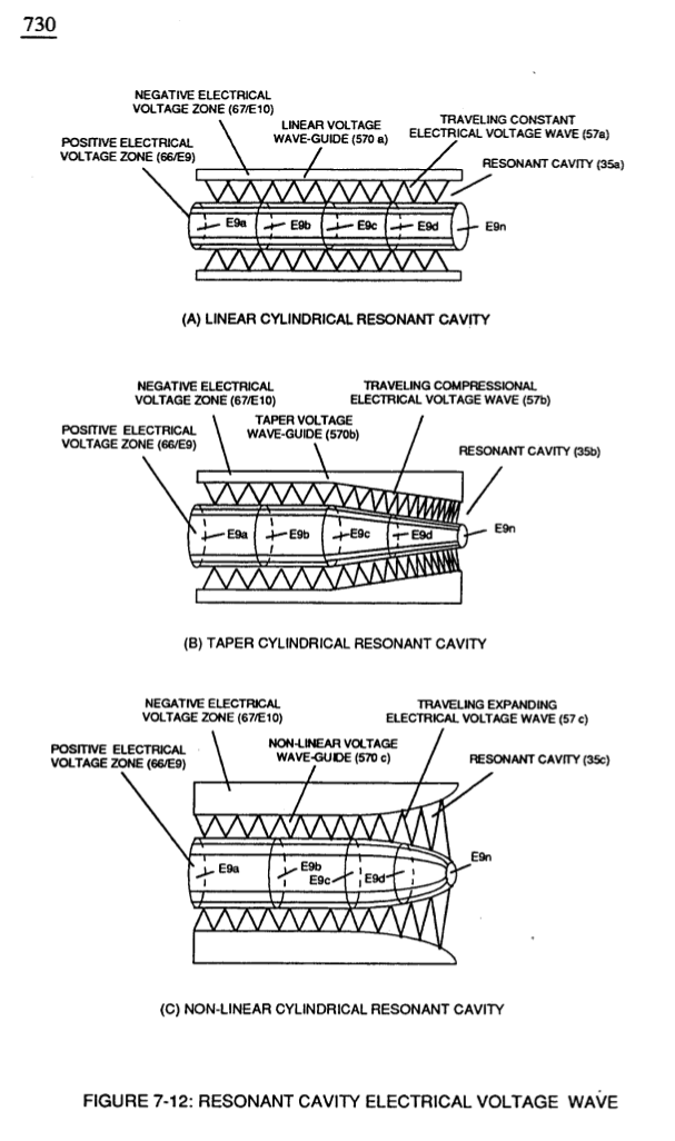](https://stanslegacy.com/uploads/images/gallery/2023-12/apuQHdvTLUsbYOQ2-image-1702698044180-40-41.png) | **Voltage Graph** (750) of Figure (7-14) [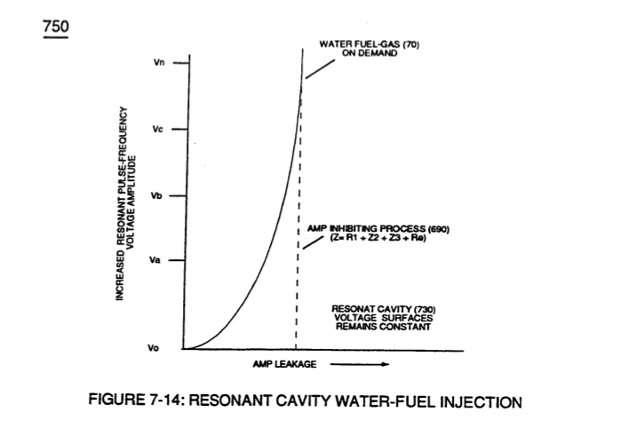](https://stanslegacy.com/uploads/images/gallery/2023-12/1jsle38mbqxsbN9r-image-1702698053508-40-51.png) |
| (see 740 of Figure 7-13) [](https://stanslegacy.com/uploads/images/gallery/2023-12/4defBEHSGj19nu8C-image-1702596417682.png) | (E9/10) of Figure (6-2) [](https://stanslegacy.com/uploads/images/gallery/2023-12/RNfeRJjKbMqMBmxa-image-1702269370435.png) **Compressional Wave-form** (B) of Figure (7-12) [](https://stanslegacy.com/uploads/images/gallery/2023-12/jeEQIngugGcTz3z8-image-1702596394739.png) |
Switching the member of **Secondary Coil-Array** (505a xxx 505n) maximizes electrical power transfer from **Primary Coil** (26) to **Secondary Coil** (52) by keeping **Voltage Amplitude** of **Pulse-train** (49a xx 49n - T3 - 49a xxx 49n) constant.
# Mode of Operability [](https://stanslegacy.com/uploads/images/gallery/2023-12/sOAwij4rY2PttCc4-image-1702698335874-45-33.png)The established "mode-of-operability" of VIC Coil Assembly (580) of Figure (6-1), now, allows **Voltage Potential** (Vn) of **opposite voltage polarity** (66/SS' - 67/RR') to increase and be attenuated up to and beyond 20 Kilovolts while inhibiting and restricting amp leakage in the milliamperes range .... establishing operational parameter of utilizing **Opposite Electrical Attraction Force** (SS' - RR') of high voltage intensity (Vn) to instantly release thermal explosive energy (gtnt) from natural water.**Voltage Compressional Wave-form** (35b) and **Expanding Voltage Waveform** (35c) increases the intensity of applied pulsating opposite electrical attraction force (55'-RR'a xxx SS'-RR'n) even further during each new pulse-cycle (T2 next T2) across water gap (616)
... increasing **Thermal Explosive Energy-yield** (gtnt) to higher energy-levels (gtnta xxx gtntn) beyond applied excitation voltage (Vn) by simply altering **Voltage Surfaces** (35b/35c) as in reference to **Linear Voltage Surfaces** (35a), as illustrated in (730) of Figure (7-12). **Pulse Off-time** (T2) of Figure (7-8) as to (620) of Figure (7-1) is adjusted to compensate for the rise and fall of magnetic coupling field (71) to produce applied **Unipolar Wave-forms** (64a xxx 64n) entering into **Wave-guides** (35a/35b/35c). [](https://stanslegacy.com/uploads/images/gallery/2023-12/pmOZtz5IJZzxP9rs-image-1702698415485-46-53.png)Less water contaminants nets even higher energy-yield (gtnta xxx 85a - 85h xxx gtntn), as illustrated in Water Chart (760) of Figure (7-15).
> In terms of **thermal explosive energy-yield** (gtnt) under dynamic pressure of compression approximately 7.4 (μl) microliter of a liquid-volume of a water droplet per injection cycle is all that is required to run the Dune Buggy 1600cc 50hp VW I.C. engine at 65 m.p.h. on the open road; > > whereas, a typical 325 hp diesel I.C. truck-engine would require about 48.1 (μl) microliters of a water droplet per injection cycle to accomplish the same open road performance. (see WFC Water vs Gasoline Energy Content Equations (memo WFC 429). [WFC 429 - Optical Thermal Lens](https://stanslegacy.com/books/the-birth-of-new-technology/chapter/wfc-429-optical-thermal-lens) # WFC 426 - Illustrations| [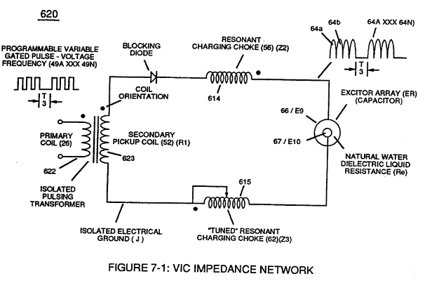](https://stanslegacy.com/uploads/images/gallery/2023-12/N33n4yjmE7kgMcy3-image-1702446340346.png) | [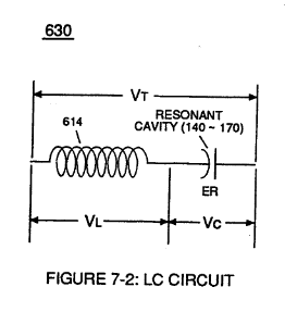](https://stanslegacy.com/uploads/images/gallery/2023-12/150OY8ZWHRmLJ4Zc-image-1702446347841.png) | [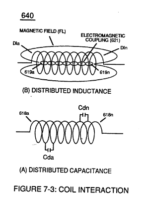](https://stanslegacy.com/uploads/images/gallery/2023-12/hXCKlWYvPKh8fDP4-image-1702446358439.png) | [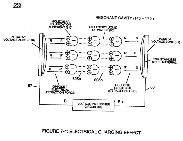](https://stanslegacy.com/uploads/images/gallery/2023-12/qkarW1lNxwhBeV9t-image-1702446367826.png) |
| [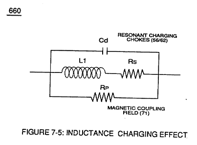](https://stanslegacy.com/uploads/images/gallery/2023-12/575shrfzd5rBK8Cd-image-1702446379373.png) | [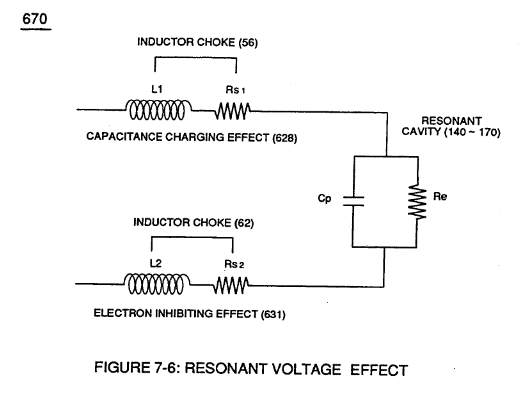](https://stanslegacy.com/uploads/images/gallery/2023-12/YkypHSuvzdEmVUF3-image-1702446389842.png) | [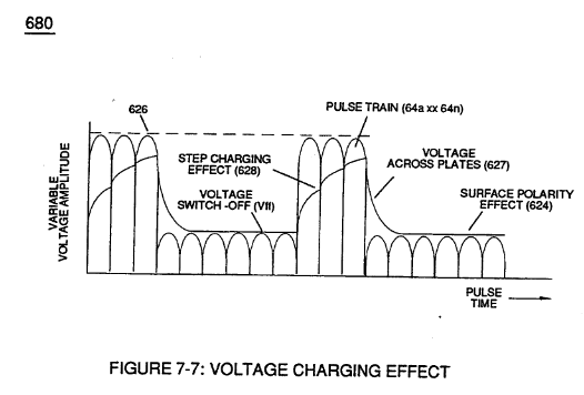](https://stanslegacy.com/uploads/images/gallery/2023-12/iOu00bYgXilUXFAf-image-1702446398689.png) | [](https://stanslegacy.com/uploads/images/gallery/2023-12/bAVItVohodNi6mwc-image-1702446407451.png) |
| [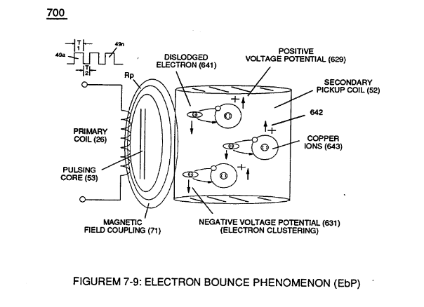](https://stanslegacy.com/uploads/images/gallery/2023-12/06znou7ARQNGA60Q-image-1702446420154.png) | [](https://stanslegacy.com/uploads/images/gallery/2023-12/zQ3M8DOyL8aSBVTw-image-1702446431428.png) | [](https://stanslegacy.com/uploads/images/gallery/2023-12/cMK1JqHzBqOhpF82-image-1702446439945.png) | [](https://stanslegacy.com/uploads/images/gallery/2023-12/iy2T2mw378gzaURS-image-1702446452554.png) |
| [](https://stanslegacy.com/uploads/images/gallery/2023-12/GTj6TkpNF3IswUDM-image-1702446469135.png) | [](https://stanslegacy.com/uploads/images/gallery/2023-12/uVzoZoMe3mI0kWZm-image-1702446478677.png) | [](https://stanslegacy.com/uploads/images/gallery/2023-12/IF96LOcos6YPtOFi-image-1702446488157.png) |
The established "State Space" is governed by either one of two variables being of either "**Static**" or "**Dynamic**" state of condition.
**Dynamic State condition** is a variable of condition that is changing all the time; whereas, **Static variable of condition** is set at some point but then never changes.
A point in "State Space" represents the state of the flame-system at a given time and is either in an synchronized and synchrony movement. Interaction of either "**Static State Space**" or "**Dynamic State Space**" in similar state of conditions or opposite conditions of "states" allows "**Energy-Vectoring**" of the hydrogen flame-front or flame projection of trajectory ... establishing an interrelationship on how to design retrofit the *water fuel injector®* to any existing type of energy consuming device. **[](https://stanslegacy.com/uploads/images/gallery/2023-12/fpjEFFsgYuAvNvNI-image-1702267792932.png)****Static variables** **condition** is established when the resultant gas pressure is held constant with the never-changing static electrical stress of opposite polarity of **Voltage Pulse-Wave** (64) of Figure (3-20) of WFC memo 422DA.
**Dynamic variable conditions** exist when both the applied electrical stress of opposite polarity and dynamic gas pressure are continually changing in a preset time frame. Where, **Combinatorial variable** conditions is a "State Space" function of subjecting constant static gas pressure to an ever-changing electrical stress of opposite polarity (RR'-SS').
And, **Differential dynamic variables** condition of"**State Space**" is accomplished whenever changing dynamic electrical stress of opposite polarity (RR'-SS') encounters a negative (decrease/drop-in) dynamic gas pressure. In each and all "Space State" of changes, the combustible gas atoms of water is/are "**Electrically Stressed**" under "**different**" pressure levels to bring-on the triggering point of thermally igniting the combustible gases of water beyond or away from **"Stable State" of Equilibrium**. **Voltage Tickling of State Space** under "**Resonant Electrical Stress**" without amp influxing while "Tuning-ln" to the dielectric properties of water is herein referred to in this WFC Tech-manual as "**Resonant Action**." # 8-2 - Traveling Voltage Wave-Guides The formation of tubular **Traveling Voltage Wave-guide** (570a) of Figure (7-12) (WFC Memo 426) as to (770) of Figure (8-1) is physically formed when **positive electrical voltage surface** (66/E9) and **negative electrical voltage surface** (67/E10) are placed in parallel space relationship to form voltage surfaces (E9/E10) about an cylindrical axis of rotation having space-gap (35) there between and thus, fanning **Cylindrical Resonant Cavity** (730A) of Figure (7-12) as to (770A) of Figure (8-1) when **space-gap** (616) of Figure (720) exposes **injected water bath** (85) to unipolar pulse-oscillation of high voltage intensity of **opposite polarity** (67/66) as to (780) of Figure (8-2) which, in turn, propagates **opposite electrical attraction force** (RR' \_ 88') of Figure (7-4), as illustrated in (590) of Figure (6-2) as to (585) of Figure (8-1).| (770) of Figure (8-1) | (730A) of Figure (7-12) [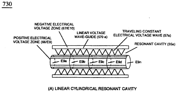](https://stanslegacy.com/uploads/images/gallery/2023-12/UMaHxPz2v93pnLY9-image-1702269030554.png) |
| (590) of Figure (6-2) | (780) of Figure (8-2) 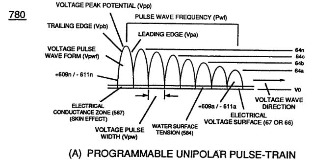 |
| (690) of Figure (7-8) (WFC memo 426) [](https://stanslegacy.com/uploads/images/gallery/2023-12/hlsTAFg22rG2oHPG-image-1702269702651.png) | (580) of Figure (6-1) (WFC memo 425) [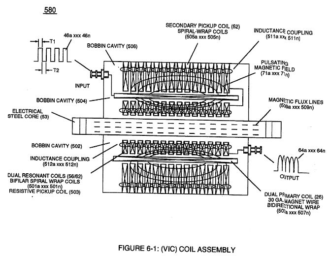](https://stanslegacy.com/uploads/images/gallery/2023-12/lpHPcvNC6u1k5L4J-image-1702269762692.png) | (780A) Figure (8-2)  |
| (57) of Figure (6-2)  | (570) of Figure (7-12)  | (720) of Figure (7-11) [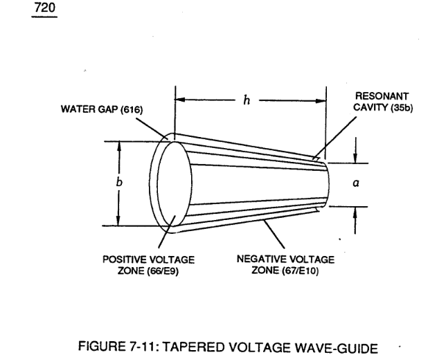](https://stanslegacy.com/uploads/images/gallery/2023-12/SSjawAdIQPIrAa1W-image-1702269999016.png) |
Together, the **Voltage Coefficient of Water** (e/Eo) of **Equation (Eq 21)** and the **Voltage Coefficient of the stainless steel** (s/s) material fanning voltage surfaces (E9/E10), now, allows the establishment and performance of **Traveling Electrical Voltage Wave-Guide** (583/602) since electrical conductance zone (587) between electrical surface (S) (E9/E10) and the **dielectric surface tension of water** (584) acts and performs as a electrical conductor (*Skin Effect*)
[](https://stanslegacy.com/uploads/images/gallery/2023-12/75y1Dd64tmxB7EXs-image-1702270436125.png) ... since electrical transmission zone (587) is almost free of electron leakage ...since **Water Bath** (85) is a dielectric-liquid (typically 78.54Q) that does not like to transfer nor exchange electrons... thereby, maintaining **voltage amplitude potential** (Vo - 64a - 64b - 64c - Vn) of Figure (8-6) without experiencing amp arc-over across **Water-Gap** (616) in any appreciable amount
... allowing pulsating opposite electrical attraction forces (RR' / SS') to perform the work of "**Electrically Charging**" water bath (85) to bring-on and trigger **Hydrogen Fracturing Process** (90) of Figure (5-5), as illustrated in **Energy Pumping stage** (520) of Figure (5-3).| Figure (8-6) [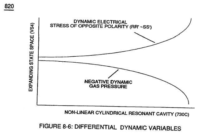](https://stanslegacy.com/uploads/images/gallery/2023-12/cSWjB8OpUFVJNkvG-image-1702270498774.png) | (90) of Figure (5-5) [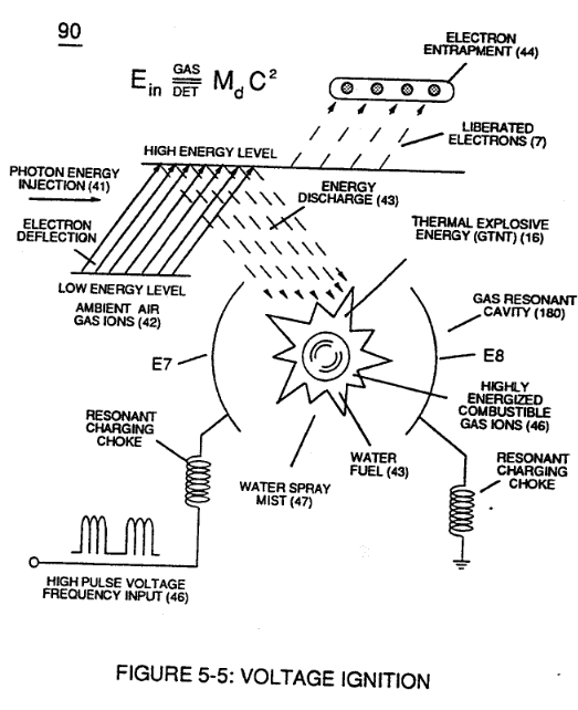](https://stanslegacy.com/uploads/images/gallery/2023-12/Ab6wiinjdoj3L05Y-image-1702270528283.png) |
| (520) of Figure (5-3) [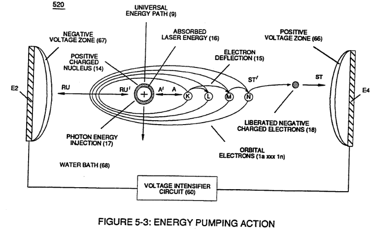](https://stanslegacy.com/uploads/images/gallery/2023-12/xMnZYy37P3CmdRnb-image-1702270566378.png) |
| (690) of Figure (7-8) [](https://stanslegacy.com/uploads/images/gallery/2023-12/hlsTAFg22rG2oHPG-image-1702269702651.png) | Circuit Resistance Equation (Eq 9) [](https://stanslegacy.com/uploads/images/gallery/2023-12/QFn7lh4KsOWwWemb-image-1702271103815.png) |
| (57) of Figure (6-2)  | (770) of Figure(8-1)  |
| Figure (8-2) [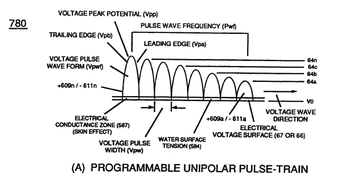](https://stanslegacy.com/uploads/images/gallery/2023-12/K0frwQoGm9kBtSzp-image-1702271309723.png) |
| Figure (7-8) [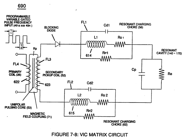](https://stanslegacy.com/uploads/images/gallery/2023-12/m3lalNlOCvPkRPWy-image-1702271420665.png) |
Thereby, preventing coil-ringing during each pulse off-time ...allowing **Electron Bounce Phenomenon (EbP)** to occur without amp influxing within **VIC Matrix Circuit** (690) of Figure (7-8) as so governed by **Circuit Resistance Equations** (Eq. 9) which, inactivated electrical-state, allows **positive** **Voltage Pulse-Wave** (583) to be duplicated in succession to form **Voltage Pulse Train** (66 - 583a xxx 583n), as illustrated in (770) of Figure (8-1).
**Circuit Resistance Equations** (Eq. 9):
[](https://stanslegacy.com/uploads/images/gallery/2023-12/6jPXw2GVw4GMA908-image-1702271772247.png)| (770) of Figure (8-1) [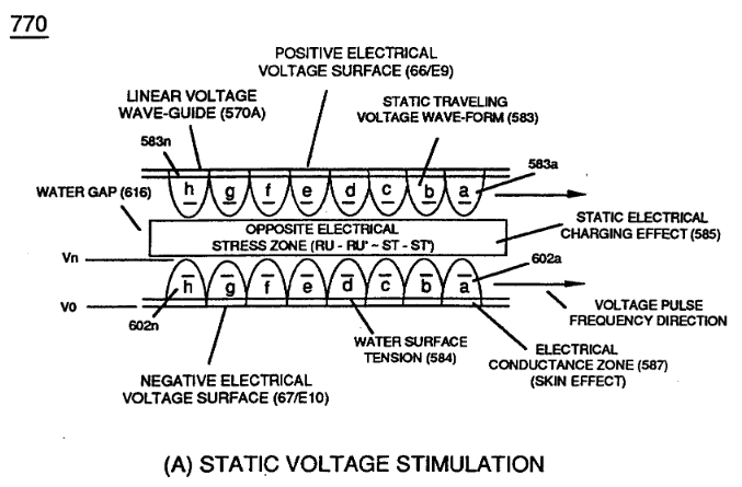](https://stanslegacy.com/uploads/images/gallery/2023-12/8GGrQX1Jjt7mvMGp-image-1702271897348.png) |
| (631) of Figure (7-9) [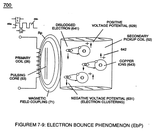](https://stanslegacy.com/uploads/images/gallery/2023-12/O0pu0cnx1RsmnYYN-image-1702271955548.png) | (52) of Figure (7-8) [](https://stanslegacy.com/uploads/images/gallery/2023-12/m3lalNlOCvPkRPWy-image-1702271420665.png) |
| (Cp) of Figure (7-8) [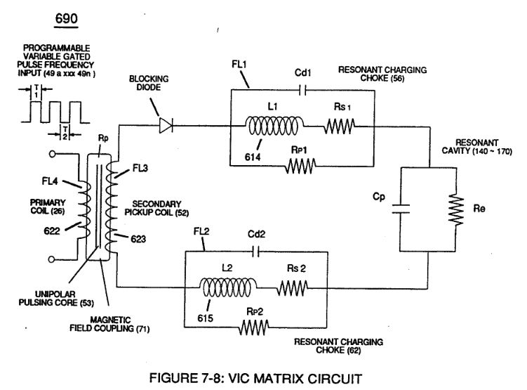](https://stanslegacy.com/uploads/images/gallery/2023-12/nQVfjamdtJFJvRCa-image-1702272513069.png) | (770 A) of Figure (8-1) [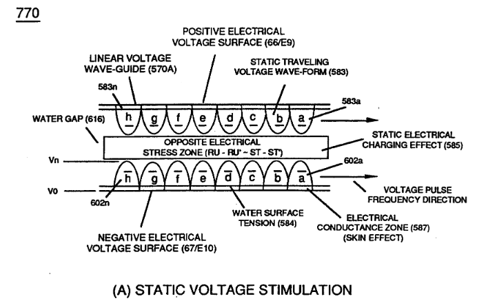](https://stanslegacy.com/uploads/images/gallery/2023-12/KfVXSTcn2OtrCvSc-image-1702272559085.png) |
| (650) of Figure (7-4) [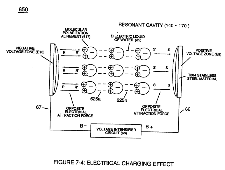](https://stanslegacy.com/uploads/images/gallery/2023-12/EYsLTj869BllN2DQ-image-1702272614387.png) | (770 B) of Figure (8-1) [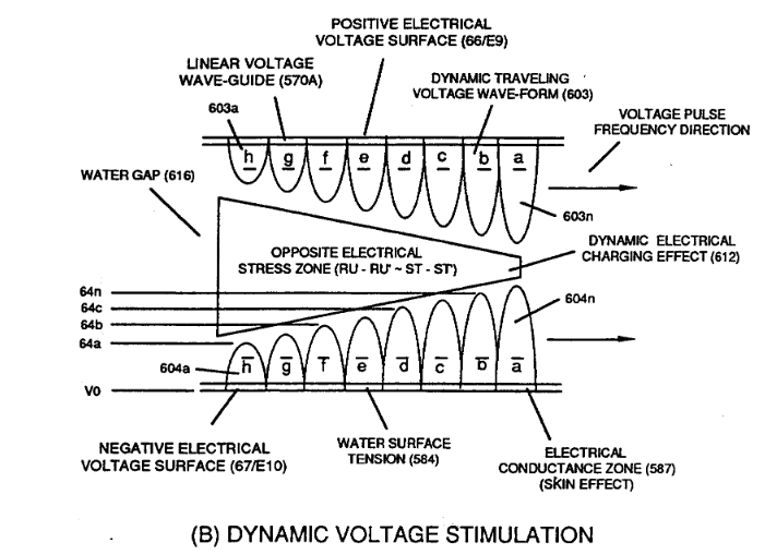](https://stanslegacy.com/uploads/images/gallery/2023-12/w4WjhWnOLNUwE66I-image-1702272586072.png) |
| (780 B) of Figure (8-2) [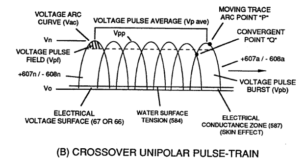](https://stanslegacy.com/uploads/images/gallery/2023-12/uFEaYqiZrGedCUlG-image-1702272703622.png) |
Whenever, **Voltage Excursion Point "P"** is always changing in a given space-time, "**State Space**" is referred to as “**Dynamic State Space;**" whereas, "**Static State Space**" exists when Voltage Excursion Point "P" remains constant during a precise period of space-time at **Peak Voltage Potential (Vpp)** forming **clipped Voltage Pulse Wave-form (Vcwf)** during **Voltage Pulse Shaping** by way of **Programmable Pulsing Circuit** *(WFC project 422DA/423DA)* electrically interfaced with **VIC Matrix Circuit** (690), as illustrated in (780) of Figure (8-2).
| (780 A/B/C) of Figure (8-2) [](https://stanslegacy.com/uploads/images/gallery/2023-12/9dEkuBFdoCvCodGB-image-1702272308669.png) | ||
| [780 A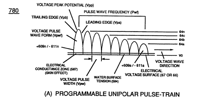](https://stanslegacy.com/uploads/images/gallery/2023-12/lV3CbvPQZMJCsKGY-image-1702272266268.png) | [780 B](https://stanslegacy.com/uploads/images/gallery/2023-12/dFOvbALm6ih03Ugl-image-1702272276618.png) | [780 C](https://stanslegacy.com/uploads/images/gallery/2023-12/okw8r7dhwCLGIE2s-image-1702272291938.png) |
**Dynamic State Space** causes **Opposite Electrical Attraction Force** (RR' - SS') to continually vary in electrical intensity (RR'SS' cei) as to formation of **Voltage Peak Curve (Vpc)**; wherein, Static State Space allows **Opposite Attraction Force** (RR' -SS') to remain at constant electrical intensity (RR' - SS' cei) when **Peak Voltage Potential (Vpp)** is clipped in forming **Arc-Line (Val)**, as illustrated in (780C) of Figure (8-2).
**[](https://stanslegacy.com/uploads/images/gallery/2023-12/dFOvbALm6ih03Ugl-image-1702272276618.png)Crossover Unipolar Pulse Train** (780B) is used when particle oscilIation of the water molecule atom (s) is/are to be continually electrical stressed (RR' -SS' vei) under changing conditions of higher magnitude (**Compressing Voltage Pulse Wave-form**) than the use of **Planar Unipolar Pulse Train** (780A).
**[](https://stanslegacy.com/uploads/images/gallery/2023-12/okw8r7dhwCLGIE2s-image-1702272291938.png)Clipped Unipolar Pulse Train** (780C) is used to encourage further increase in atomic dwell-time capable of raising **Atomic Energy Level (AEI)** of the **Water Atoms** to even a higher energy-state before **Snapping-Action** occurs when **Unipolar Pulse Wave (Upw)** returns to ground state (Vo) after voltage propagation (Vpa/Vpb).
Of course, the repetition-rate of "**Atomic Snapping Action**" **(Asa)** *(the number of Voltage Pulse Fields Vpf occurring per unit of space-time)* directly determines the resultant energy level of **Static Electrical Charging Effect (585)** of Figure (8-1) since “**Particle Oscillation**" is being used as a “**Energy Generator**" **(EGpo)**, as so subscribed in memo (424) titled **Atomic Energy Balance of Water** as to the functional parameters associated with **Dynamic Voltage Potential Wave-form** (600) of Figure (6-3) which uses Voltage Pulse Potential of opposite electrical polarity of attraction (RR' - SS' as to RU/RU' – ST/DST') to perform work in the following sequence of events in an instant of time: **Electrical Polarization Process** (160) (elongating the water molecule ... changing the **time share rate** of the covalent electrons ... switching off the covalent bond by attenuating the electromagnetic fields of the electrical stressed atoms undergoing molecule separation; **Universal Energy Priming Stage** (500) (particle oscillation as a energy generator by deflecting atomic particles under changing electrical stress); **Liquid to Gas Ionization Stage** (230) (ejecting electrons from the atomic structure under divergent electrical stress); and **Thermal Gas Triggering Stage** (E9d) (gas igniting the electrically stress combustible gas atoms farthest from the state of electrical equilibrium)... triggering **Hydrogen Fracturing Process** (90) (subcritical-state combustible gases being spark-ignited under **Electrical Resonance of Stress**).
In terms of **Particle Oscillation (Poe)** as a **Energy-Generator (EGpo)**, if **Voltage Arc Line (Val)** length is extended while **Voltage Amplitude** (xx 64a - 64b - 64c - Vn) is adjusted to higher **Voltage Peak-Potential (Vpp)** then greater atomic interaction (585) of Figure (8-1) *(see WFC memo 424 titled [Atomic Energy Balance of Water](https://stanslegacy.com/books/the-birth-of-new-technology/chapter/wfc-424-atomic-energy-balance-of-water "WFC 424 - Atomic Energy Balance of Water"), once again)* occurs when particle oscillation (Poe) of deflection of atomic mass (see 550 of Figure 5-8) (**atom elongation**) is electrically stressed farthest from the point of state of atomic-equilibrium by way of **opposite Voltage Electrical Attraction Force** (RR' - SS' as to RU/RU' - ST/ST'), as further illustrated in (500) of Figure (5-1) as to (510) of Figure (5-2).| (585) of Figure (8-1) [](https://stanslegacy.com/uploads/images/gallery/2023-12/xeLxSpcNFI8SicTI-image-1702273137185.png) | (550 of Figure 5-8) [](https://stanslegacy.com/uploads/images/gallery/2023-12/EWOSQ1jArMdSS4fB-image-1702273162911.png) |
| (500) of Figure (5-1) [](https://stanslegacy.com/uploads/images/gallery/2023-12/Hpg7rh0OweIs9pZ4-image-1702273184697.png) | (510) of Figure (5-2) [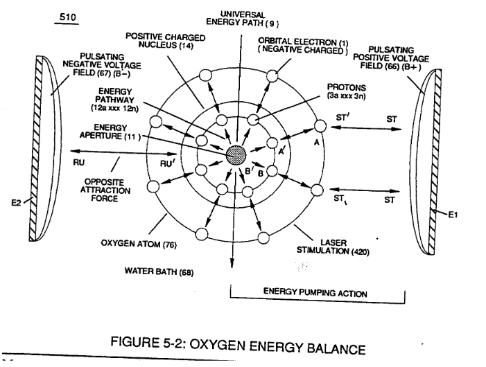](https://stanslegacy.com/uploads/images/gallery/2023-12/pGGcxWvzq0zmq0UW-image-1702273224503.png) |
**Voltage Tickling of State Space** under "**Resonant Electrical Stress**" without amp influxing while ''Tuning-In' to the dielectric properties of water is herein referred to in this WFC Tech-manual as "**[Resonant Action](https://stanslegacy.com/books/the-birth-of-new-technology/page/resonant-propagation "Resonant Propagation"),**" as illustrated graphically in Figure (5-4 A,B,C) as to **Resonant Cavity** (170) of Figure (3-25) as to Figure (1-13).
| 5-4 A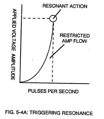 | 5-4 B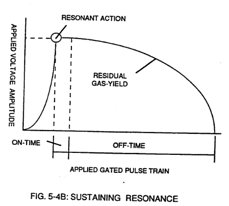 | 5-4 C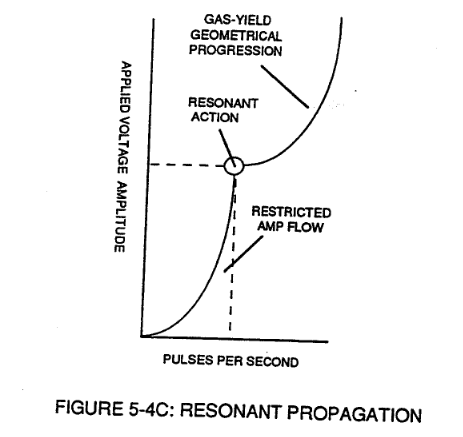 |
| (170) of Figure (3-25) [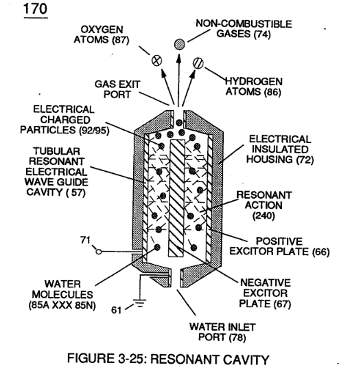](https://stanslegacy.com/uploads/images/gallery/2023-12/sqYT2rjyDmzKCPvF-image-1702273538410.png) | Figure (1-13) [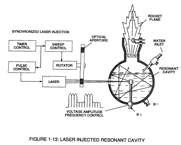](https://stanslegacy.com/uploads/images/gallery/2023-12/3LFtV3nLyzTONB6P-image-1702273587972.png) |
| Figure (4-5) [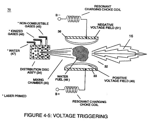](https://stanslegacy.com/uploads/images/gallery/2023-12/VDLLMzhQ54xgmWVi-image-1702320373763.png) | (40) of Figure (4-2) [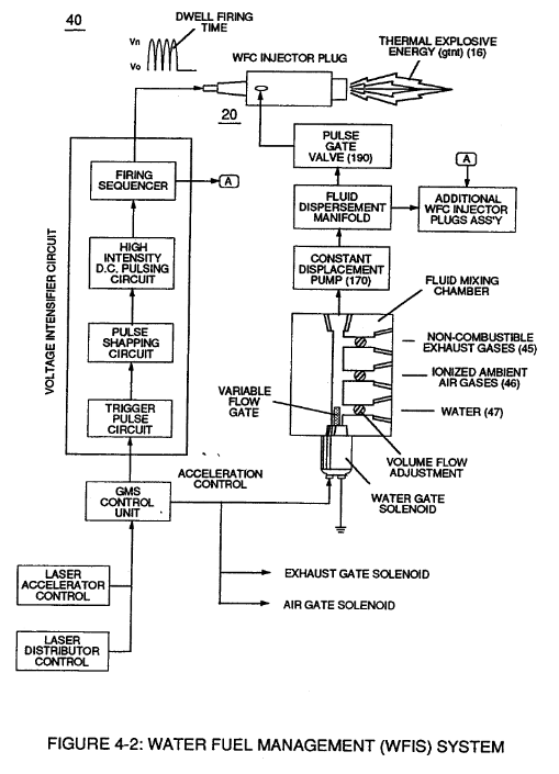](https://stanslegacy.com/uploads/images/gallery/2023-12/vx6WcGbiUr3kcKSg-image-1702320411607.png) |
| **Resonant Cavity** (90) of Figure (4-7) [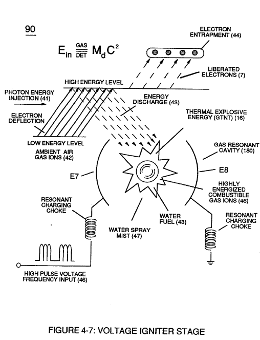](https://stanslegacy.com/uploads/images/gallery/2023-12/qBcEd39TqFWcCgNd-image-1702320430535.png) | (730) of Figure (7-12) [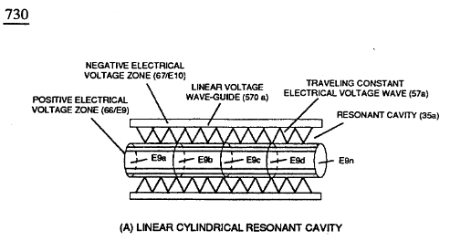](https://stanslegacy.com/uploads/images/gallery/2023-12/oDjVDsnLKUFTzYZg-image-1702320474242.png) |
In terms of Voltage Pulse Wave-form (s) (Vpwt) several ''**Electrical Operational Parameters**" exist:
**Dynamic State Space (Dss)** which continually changes/varies Electrical Attraction Force (RR' - SS' as to RU/RU' - ST/ST') from low stress intensity (S-low) to high stress intensity (S- high) and back to low stress point (S-low) as to **Arc Curve (Vac)** forming **Voltage Pulse Field (Vpt)** atop **Voltage Pulse Burst (Vpb)** ... which combined together (Vpf + Vpb) Electrical Stress (Es) variances corresponds to the **Voltage Pulse Shape** of each synchronized **opposite Voltage Pulse Wave** (583 - 602) of (770A) of Figure (8-1) being produced during applied **Voltage Pulse Operation** (49a xxx 49n);| (770A) of Figure (8-1) [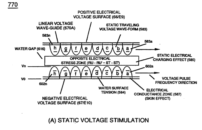](https://stanslegacy.com/uploads/images/gallery/2023-12/9BuZ5yjpADilbFEw-image-1702274506697-01-42.png) |
| **Clipped Voltage Wave-form** (780C) of Figure (8-2) [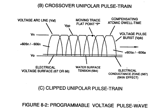](https://stanslegacy.com/uploads/images/gallery/2023-12/7QsOG4PnzICQjKMn-image-1702320617032.png) |
| (612) of Figure (8-1) [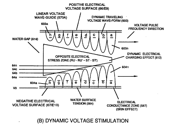](https://stanslegacy.com/uploads/images/gallery/2023-12/JFJtkwcMApIIrANl-image-1702320983338.png) |
To further adjust incoming **Voltage Priming Stage (Vps),** Unipolar Voltage Pulse Train (Vpt) is either gated full-on to allow space-time continuum or back-off in gated format from 100% to a lower percent (%) of Pulse-Frequency on-time, as illustrated in Figure (3-20).
# 8-6 - VIC Voltage Sync-Pulse Circuit **Voltage Sync-Pulse Gated Frequency** (583/602a xxx 583/602n) (603/604a xxx 603/604n) of Figure (8-1) as to (605/606a xxx 605/606n) (607/608a xxx 607/608n) (609/611a xxx 609/611n) of Figure (8-2) ... all, forming **Voltage Pulse Burst Wave** (619) as to **Unipolar Pulse-Train** (780A), **Crossover Unipolar Pulse-Train** (780B), and **Clipped Unipolar Pulse Train** (780C) as to **Traveling Voltage Wave-Action** (770) of Figure (8-1) of opposite voltage polarity (+/-) of equal Voltage-Pulse Amplitudes (+Vpp/- Vpp) are zero reference to electrical ground state (0V) by placing **Amp Inhibitor Circuit** (860) (Amp Inhibiting Coil 617, Blocking Diode 618, and **Magnetic Induction Core** 619) between electrical ground (0V) and **Center Tap** of **Dual Bifilar Secondary Pickup Coils** (616A/B) of **VIC Matrix Circuit** (690) of Figure (7-8) as to **VIC Impedance Network Circuit** (620) of Figure (7-1) , as illustrated in (840) of Figure (8-10).| [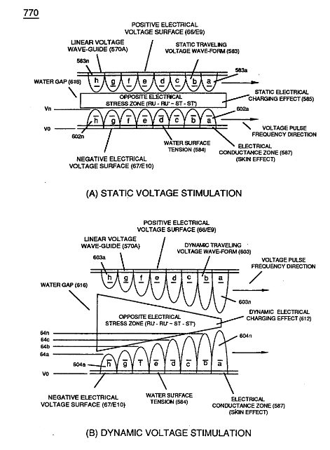](https://stanslegacy.com/uploads/images/gallery/2023-12/DFvYW7H0AkLEYkFv-image-1702322742624.png) | [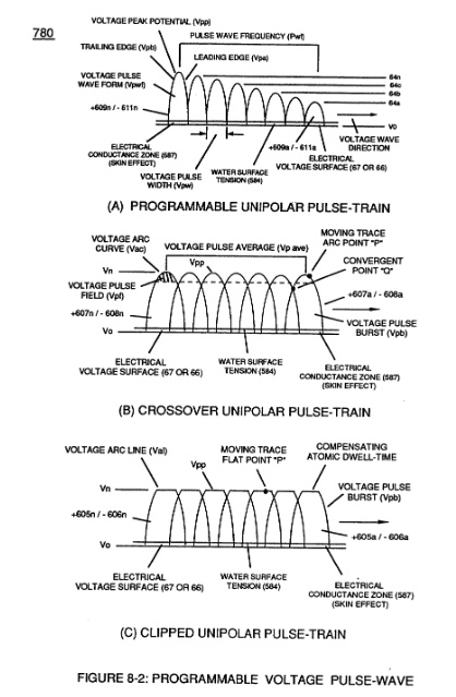](https://stanslegacy.com/uploads/images/gallery/2023-12/BA8yXHMaqNPV3DWk-image-1702322775259.png) |
| (620) of Figure (7-1) [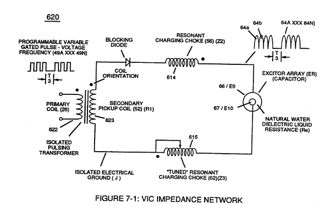](https://stanslegacy.com/uploads/images/gallery/2023-12/cKlYNDtjss0ThzDi-image-1702322896883.png) | (690) of Figure (7-8)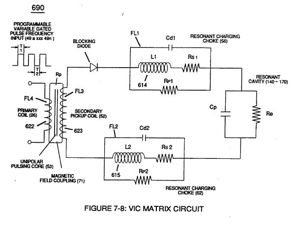 | (840) of Figure (8-10) [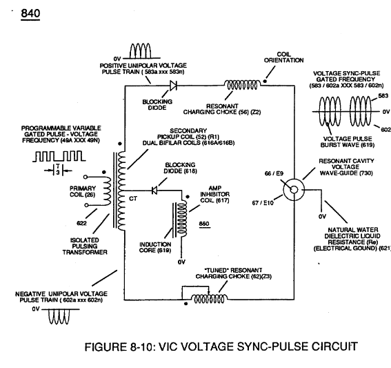](https://stanslegacy.com/uploads/images/gallery/2023-12/aSPqDjaFMLaa1kOK-image-1702322919481.png) |
By doing so, **Balance Phasing** of opposite voltage intensity (+Vpp / - Vpp) is accomplished without experiencing current influxing caused by differential variances where Negative Voltage Peak Potential (-Vpp) is less than Positive **Voltage Peak Potential (+Vpp)** or Vise Versa ... allowing Inductor **Resonant Choke Coils Electromagnetic Fields Intensity** (+Z2 / -Z3) to be, in turn, free of Electromagnetic variances of intensity (Z2 - Z3).
This non-voltage shift (**Balanced Phasing of opposite Voltage Potential**) helps prevents atom displacement during "**Snapping-Action**" by which "**Resonant Electrical Stress**" of opposite electrical polarity (RU/RU' - ST/ST') is applied equally across Water Molecule (s) (85) to propagate either **Static** (585) or **Dynamic** (612) **Electrical Charging Effect** (s) at elevated **Voltage Peak Potential** (s). **[](https://stanslegacy.com/uploads/images/gallery/2023-12/axyMmFebag8VQyKq-image-1702323131155.png)Amp Inhibiting Coil-Assembly** (617) is made up of magnetic inductance Stainless Steel 430FR wire material wrapped around a closed-loop Induction **Magnetic Core** (619) which is a separate coil-unit (860) apart from **VIC Coil Assembly** (580) of Figure (6-1).Blocking Diode (618) functions as an "**Electrical Isolator**" that prevents electrical discharge of **Dual Secondary Coil** (616A / B) during applied Pulsing Operations (49a xxx 49n).
To ensure and maintain **Capacitance Charging Effect** (650) of Figure (7-4) across Water-Gap (Cp) of (7-8) during applied pulsing operations (49a xxx 49n), **Crossover Voltage Wave-Form** (780B) as to (780C) of Figure (8-2) is generally utilized by not allowing **Convergent Point "Q"** of Figure (780B) to reach **Electrical Ground Point** (0V) when each Unipolar Voltage Pulse (Vpp) is electrical energized in phase-distance relationship to cause the **trailing edge** (Vpb) of the **first Voltage-Pulse** (Vppl) to meet the **uprising leading** edge (Vpa) of the **second Voltage Pulse Wave** (Vpp2) at a distance above ground state (OV) determined by the Space-movement of the reforming **Voltage Peak Wave** (Vppa xxx Vppn) within Voltage Pulse Width (TI), as illustrated in **Rotary Crossover Voltage Sync-Pulse Circuit** (850) of Figure (8-11) where each VIC Pickup Coils (52A-52B -52C) are axially spaced 120· apart to cause **Convergent Point "Q"** to be located 1/3 the height of **Voltage Amplitude Peak Level** (Vpp), as an example.| (650) of Figure (7-4) [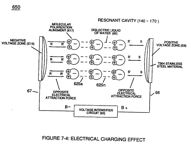](https://stanslegacy.com/uploads/images/gallery/2023-12/1qiRXOamfmvmScRA-image-1702323292175.png) | (Cp) of (7-8) [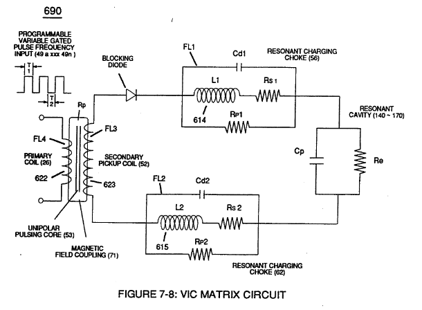](https://stanslegacy.com/uploads/images/gallery/2023-12/w67crG6IdBjVqaeH-image-1702323311288.png) |
| **Convergent Point "Q"** of Figure (780B) [](https://stanslegacy.com/uploads/images/gallery/2023-12/dFOvbALm6ih03Ugl-image-1702272276618.png) | **Rotary Crossover Voltage Sync-Pulse Circuit** (850) of Figure (8-11) [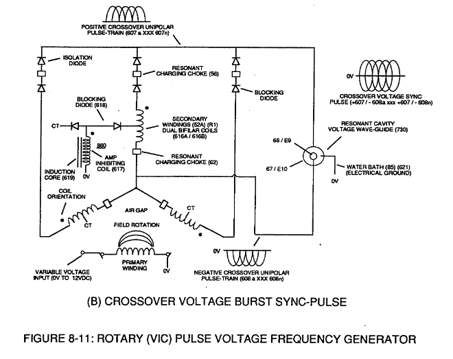](https://stanslegacy.com/uploads/images/gallery/2023-12/kqcIl68vMn9vtrxB-image-1702323395893.png) |
For example, **Taper Resonant Cavity** (590) of Figure (6-2) as to (820B) of Figure (8-6) is ideally suited for internal combustion I. C. engines as well as Rocket Engines where high thrust-yield of explosive power (gtnt) (582B) is required;
| (590) of Figure (6-2) | (820B) of Figure (8-6) [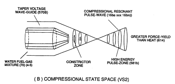](https://stanslegacy.com/uploads/images/gallery/2023-12/RBKfq1Pt50pX2ZB8-image-1702321635429.png) |
whereas, **Expanding Resonant Cavity** (730C) of Figure (7-12) as to (820C) of Figure (8-6) is best suited for Furnace Applications. **Linear Resonant Cavity** (730A) of Figure (7-12) as to Figure (820A) is for Cutting-Torch applications (582) ... to mention a few.
| (730C) of Figure (7-12) [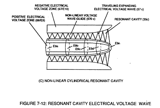](https://stanslegacy.com/uploads/images/gallery/2023-12/Iwkoe2NNPjsY0Anw-image-1702322074845.png) | (820C) of Figure (8-6) [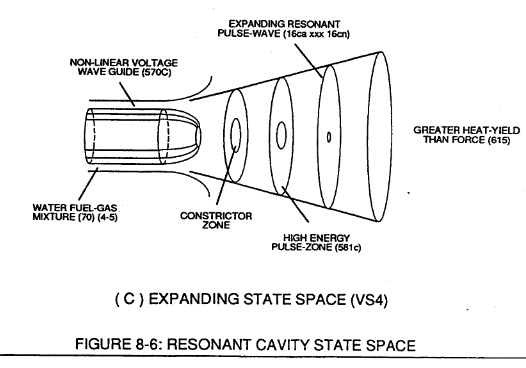](https://stanslegacy.com/uploads/images/gallery/2023-12/7QDYeZX39oEeQ9KX-image-1702322145308.png) |
| (730A) of Figure (7-12)[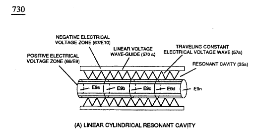](https://stanslegacy.com/uploads/images/gallery/2023-12/ZpPc6QfiFXuZ1dgZ-image-1702322057919.png) | Figure (820A) of Figure (8-6) [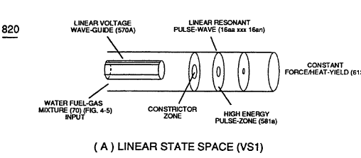](https://stanslegacy.com/uploads/images/gallery/2023-12/eQoKFp3JFU8iV4zm-image-1702322166170.png) |
| [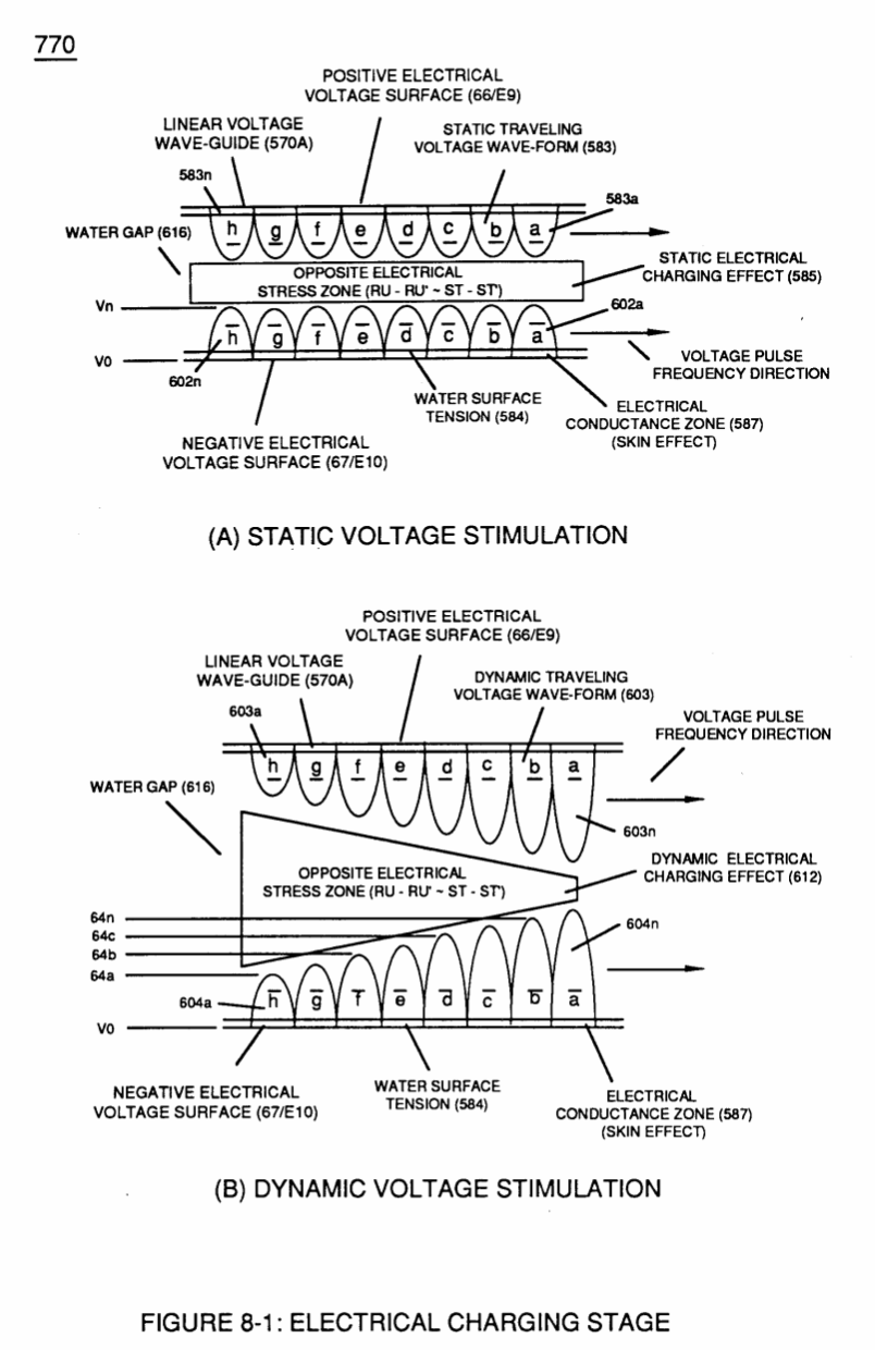](https://stanslegacy.com/uploads/images/gallery/2023-12/SMi1QUhqx7zCe5DY-image-1702325562912-12-39.png) | [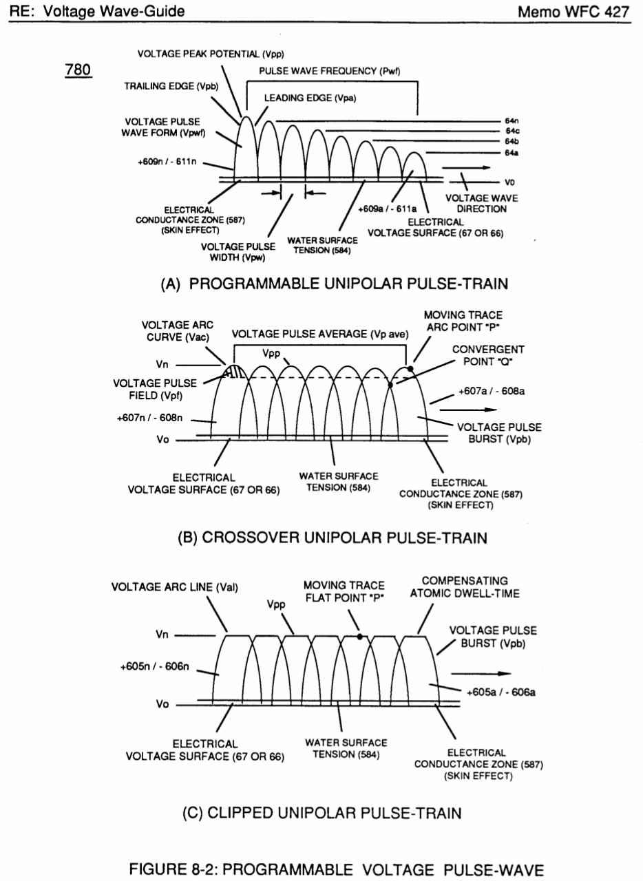](https://stanslegacy.com/uploads/images/gallery/2023-12/ffuLUdQyBdMLqVSW-image-1702325586823-13-03.png) | |
| [](https://stanslegacy.com/uploads/images/gallery/2023-12/P3uPTitNlaAPJXZc-image-1702325598462-13-16.png) | [](https://stanslegacy.com/uploads/images/gallery/2023-12/VhjznBwfpOdDMX03-image-1702325607890-13-24.png) | [](https://stanslegacy.com/uploads/images/gallery/2023-12/IjLp8GMWekCM8IRi-image-1702325617630-13-34.png) |
| [](https://stanslegacy.com/uploads/images/gallery/2023-12/sDxMpcFUOqD9wiaa-image-1702325655671-14-12.png) | [](https://stanslegacy.com/uploads/images/gallery/2023-12/XwPllCtAwPn1ROJ6-image-1702325666045-14-23.png) | [](https://stanslegacy.com/uploads/images/gallery/2023-12/sTVlPUQg1u5FxgBu-image-1702325696254-14-53.png) |
| [](https://stanslegacy.com/uploads/images/gallery/2023-12/UGmU868muzxJo20M-image-1702325704970-15-02.png) | [](https://stanslegacy.com/uploads/images/gallery/2023-12/wEG6rLFZXg3H1FvD-image-1702325714713-15-11.png) | [](https://stanslegacy.com/uploads/images/gallery/2023-12/Jj0wxfsFQmtbcNbz-image-1702325726228-15-23.png) |
| [](https://stanslegacy.com/uploads/images/gallery/2023-12/iSP7gXLvMPGB1Wph-image-1702325735085-15-31.png) |
Remember, water, of course, is free, abundant, and energy recyclable.
**WFC Exhaust Air Reclaimer** technology utilizes the **WFC Electrical Polarization Process** to reverse the degradation effect of burning fossil-fuel ...liberating chemical-oxides oxygen 02 molecules once again for reuse under "**Earth Ecological Life Support System**" ... collecting atoms under static charged for industrial reuse ... resulting in revitalized "Clean" air once again to sustain all life- forms on Earth. **WFC Exhaust Air Reclaimer** functions in the following way: > In almost all cases of scientific accomplishments, spin-off technology occurs. The Water Fuel Cell technology of Inventions is no exception to this rule. > > For every cause there is a reason and for every reason there is an answer and for every answer there is progress. > > Without scientific progress, we can not hope to cope with, nor solve, the needs of the World. > > The answers given below are for this purpose and this purpose only. # Electrovalent Bonding In similar manner by which polar **Water Molecule** unlike atoms (Hydrogen Atoms 78 / Oxygen Atom ID (210) of Figure (3-27) take-on opposite electrical Charges (B+ / B-), other gas-atoms molecule (s) experience the same **Electrical Charge Effect** (q - q') when covalent-electron sharing occurs, as illustrated in polar-molecule **Carbon Dioxide** CO2 (910) of Figure (9-2) as to allotropic molecule of **Ozone** 03 (930) of Figure (9-4). (210) of Figure (3-27)| (910) of Figure (9-2) [](https://stanslegacy.com/uploads/images/gallery/2023-12/N1lvKB5LMDkYXTCf-image-1702958618091-03-36.png) | (930) of Figure (9-4) [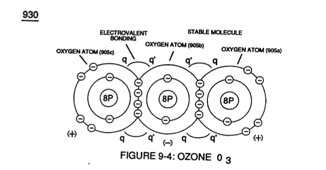](https://stanslegacy.com/uploads/images/gallery/2023-12/4i1r7jUfIPQFfK9i-image-1702959212431-13-27.png) |
Electrical intensity of **Opposite Electrical Attraction Force** (q-qa'- 907a + q-qb' - 907b) (herein after called **Electrovalent Bonding**) (total electrical bonding force between two opposite electrical charged atoms) are equivalent to the total number of electrons being used/accepted by the host atom (s) having the greater positive charged (B+) nucleus as so established under the laws of physics which states for "*every action there is an equal and opposite reaction*".
This is possible due the fact that all orbiting individual electrons display their own negative electrical charge (B-) whereas each proton-particle separately supports a positive electrical charge (B+)
... both opposite electrical charged particles (Proton as to each Electron) being equal in electrical magnitude (B+ / B-).And due to the fact that the oxygen atom does not take-on an electromagnetic charged field since its electrons pair together and spin in opposite direction.
# Ecological Support Cycle Changing **Electrovalent Bonding** of similar and non-similar atoms to form gas-molecule (s) produces different elements of substance. For example, in the combustion process of burning fossil-fuel (oil, gasoline, diesel-fuel, coal, or natural gas) in air results in unwanted airborne pollutants such as Carbon Monoxide CO, Nitric Oxide NO, Nitrogen Dioxide N02, Carbon Monoxide CO, Carbon Dioxide 2C02, Sulfur Dioxide S02, and unburned hydrocarbons ... to mention a few.Once these chemical-oxides enters/discharged into the atmosphere surrounding **Earth** (see graph 950 of Figure 9-6) other chemical interactions (oxidization) may occur under the process of "**Photochemical Bonding**" by sunlight.
For example, when Sulfur Dioxide S02 molecule **Electrovalent** link up to an Oxygen 02 molecule (920) of Figure 9-3) ... forming Sulfur Trioxides 2S03 which when mixed with rain produces "**Sulfuric Acid**" known Worldwide as "**Acid Rain**". Toxicity of these air-borne (dilution in air) chemical-oxides (907) of Figure (9-6) is/are not only endangering "**Earth Ecological Support System**" but in the formation of these airborne chemical-oxides by way of catalytic-action of combustion (burning) are extracting/consuming enormous amounts of free floating Oxygen 02 molecule (920) of Figure (9-3) out of the air (less than 20% now as compared to 30% prior to the **Industrial Age** as so determined by polar ice-cap samples) which is vital to sustain all life-forms on Earth. > (see Blue Planet cinematography-film by Imax, NASA)These increases of airborne pollutants over the years are, also, a major contributor of decreasing **Sun-Energy** (photon absorption know as the "**Green-House Effect**") (estimated 10% reduction in some parts of the World today) which is, now, allowing the viro-germ of "**Blight**" to form ... killing-off forest region I plant -life around the World.
[](https://stanslegacy.com/uploads/images/gallery/2023-12/N1lvKB5LMDkYXTCf-image-1702958618091-03-36.png)Remember, plant-life is required to convert Carbon Dioxide CO2 (910) of Figure (9-2) into liberated Oxygen 02 so that the "**Breath of Life**" is provided for all animal-life. Entrapping the Oxygen 02 molecule in the chemical-oxide process of burning fossil-fuel (s) is, also, disrupting/preventing the "**External Respiration Process**" of plants from exchanging oxygen 02 and Carbon Dioxide 2m2 between the plant-organism and its environment in the present of sun light. The reduction of sun light is further stunting the growth of plants while, simultaneously, causing plant respiration process cycling-rate to decline exponentially. Worst yet, chemical-oxide airborne pollutants derived from burning fossil-fuels are chemically interacting with the **Ozone layer** 20 miles above Earth. [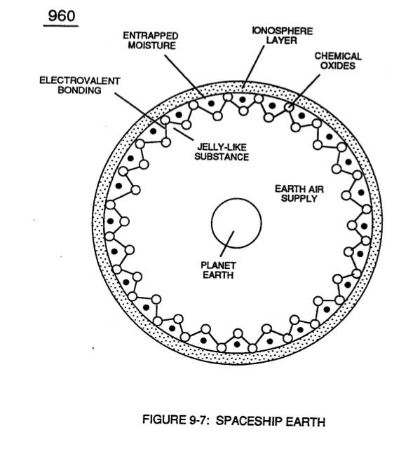](https://stanslegacy.com/uploads/images/gallery/2023-12/iHgtBiWb3NTMeF3W-image-1702958650292-04-08.png)... causing ozone layer depletion ... allowing increased ultraviolet radiation originating from the sun to pass through the air troposphere ... contributing not only to changing/altering man's "**Ecological Life Support System**" on Earth but allowing a portion of Earth "**Air Gases**" to escape into outer space. Furthermore, free-floating chemical-oxides are "**Electrovalent-Bonding**" to Earth ionosphere 'converting **Earth Air Supply** into a "**Jelly-Like**" substance ... entrapping moisture from air ... disrupting **Earth Rain Cycle**, as so illustrated in (960) of Figure (9-7).Dispersion of radioactive/chemical biological agent (s) contaminated oil supplies coming out of the **Arab Gulf War** may pose another real threat to man's survival.
Inhaling radioactive exhaust fumes from contaminated Arab oil certainly would cause Lung cancer if such a deplorable situation would be allowed to exist even for a brief period of time.
# WFC Development Objectives The primary Purpose/objective of **Water Fuel Injection System** (590) of Figure (6-2) as to "**FullSystem**" development (10) of Figure (4-1) is, in the realm of scientific quest, to help reverse the damage being done to "**Earth Ecological Life Support System**" by first of all encouraging the use of "**Water**" as a new "**Fuel**" source| **Water Fuel Injection System** (590) of Figure (6-2) [](https://stanslegacy.com/uploads/images/gallery/2023-12/iDN6sNT4uVrN1k82-image-1702697335129-28-52.png) | "**FullSystem**" development (10) of Figure (4-1) [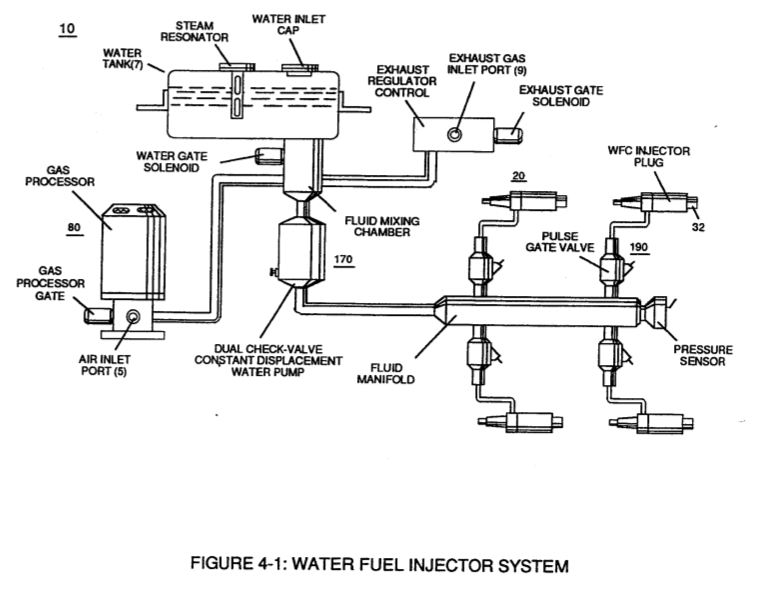](https://stanslegacy.com/uploads/images/gallery/2023-12/iBnev0cqLGy7n1Ru-image-1702959902419-24-59.png) |
Secondly, re-energizing the energy level of the air by the use of **WFC Gas Processor** (80) of Figure (1-17) by tapping into "**Universal**" energy by way of particle oscillation as a energy generator, as so illustrated in **Energy Pumping Action** (520) of Figure (5-3) as to **Energy Aperture** (570) of Figure (5-10).
| **WFC Gas Processor** (80) of Figure (1-17) [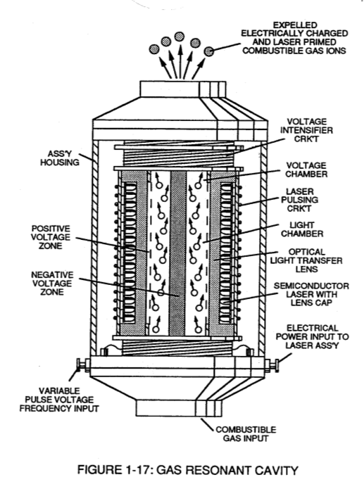](https://stanslegacy.com/uploads/images/gallery/2023-12/tqw7dXMM0YLvtx4Q-image-1702960112038-28-30.png) | **Energy Pumping Action** (520) of Figure (5-3) [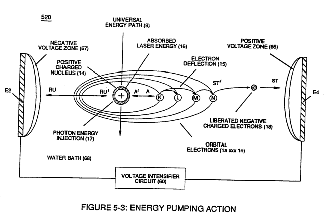](https://stanslegacy.com/uploads/images/gallery/2023-12/YtLNv2CN4ytT1k3y-image-1702949578313.png) **Energy Aperture** (570) of Figure (5-10) [](https://stanslegacy.com/uploads/images/gallery/2023-12/nUNJwiZoZa4CO5Te-image-1702521046706.png) |
And lastly, make use of **WFC Exhaust Air Reclaiming** technology (900) of Figure (9-1) to unlock and do away with the airborne chemical-oxides derived from fossil-fuel burning when ambient air passes through the Internal combustion (IC) engine running on water
[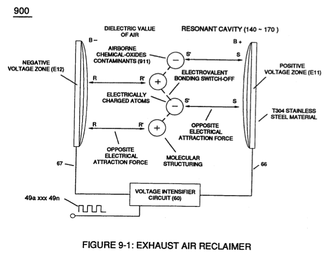](https://stanslegacy.com/uploads/images/gallery/2023-12/ZJecZJOhMgcfhbEH-image-1702958533456-02-11.png) ... thereby re-purifying our air for healthy living while maintaining the Industrial economy of the World.Remember, Water, of course, is free, abundant, and energy recyclable.
# WFC Exhaust Air Reclaimer To eliminate the possibility of expelling out any **Nitric Oxide** NO gas which is generally produced when an electrical spade occurs inside an internal combustion (lC) engine or any other chemical-oxide that may be present in the exhaust-air, **WFC Exhaust Air Reclaimer** (900) of Figure (9-1) can be utilized to comply with **U.S. Environmental Protection Agency** (EPA) clean Air Act similar in construction to **Voltage Intensifier Circuit** (110) of Figure (4-9), **WFC Exhaust Air Reclaimer** (900) of Figure (9-1) utilizes opposite electrical attraction force (RR' - SS') of voltage potential (Va xxx Vn) to separate the atoms of the **Nitric Oxide** NO molecule (typically < 1ppm when running on water) by overcoming **Electrovalent Attraction Force** (q - q') that exist between the polar-charged **Nitrogen** (B+) and **oxygen** (B-) atoms.| **WFC Exhaust Air Reclaimer** (900) of Figure (9-1) [](https://stanslegacy.com/uploads/images/gallery/2023-12/ZJecZJOhMgcfhbEH-image-1702958533456-02-11.png) | **Voltage Intensifier Circuit** (110) of Figure (4-9) [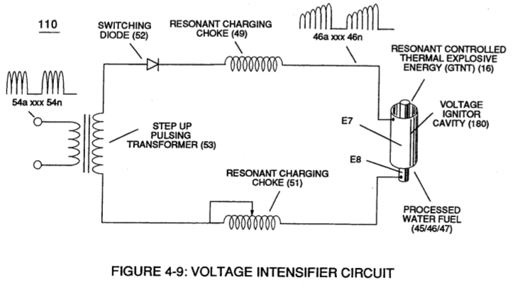](https://stanslegacy.com/uploads/images/gallery/2023-12/Hm2cxFbqW6vJwrLG-image-1702960528958-35-26.png) |
... pulling apart and separating the atoms of the **Nitric Oxide** NO molecule by way of **Voltage Dynamics** (220) of Figure (3-29) under the law of physics which states "**opposite electrical charges attracts**", as so illustrated in (900) of Figure (9-1).
| **Voltage Dynamics** (220) of Figure (3-29) [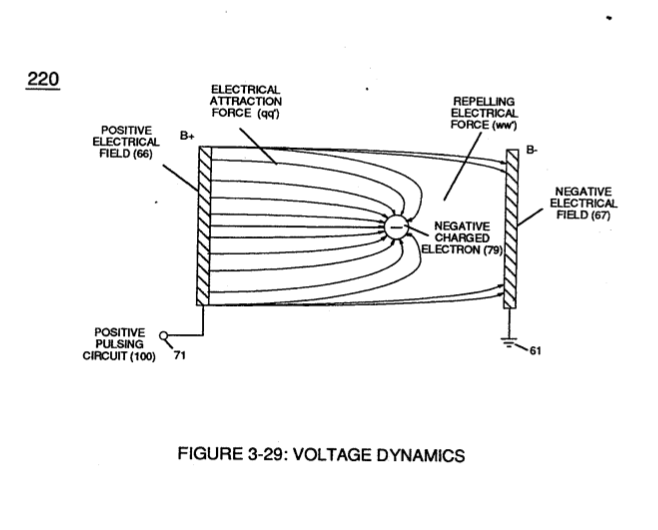](https://stanslegacy.com/uploads/images/gallery/2023-12/RJhOfGsGXf2oaUpf-image-1702960613786-36-51.png) | (900) of Figure (9-1) [](https://stanslegacy.com/uploads/images/gallery/2023-12/ZJecZJOhMgcfhbEH-image-1702958533456-02-11.png) |
Of course, water mist derived from hydrogen combustion is removed prior to engine exhaust air-gases entering into and passing through **WFC Exhaust Air Reclaimer System** (900).
Air purification by **atomic deflection** (900) of Figure (9-1) is possible since airborne atoms are neither destroyed nor created during exposure to "**Voltage**" **pulse-stimulation** (E11/E12 ... 49a xxx 49n) propagating "**Electrical Stress**" pulse-waves (Mm'- ASS') which, in turn, induces "**Electrovalent Switch-off**" phenomenon (550) of Figure (5-8).| **atomic deflection** (900) of Figure (9-1) [](https://stanslegacy.com/uploads/images/gallery/2023-12/ZJecZJOhMgcfhbEH-image-1702958533456-02-11.png) | "**Electrovalent Switch-off**" phenomenon (550) of Figure (5-8) [](https://stanslegacy.com/uploads/images/gallery/2023-12/KX53IC8u8rLuN9Ai-image-1702960678867-37-56.png) |
In alternate form, solid state electrical photon-light source (**Light Emitting Diodes**) (1100 xxx 116n) of Figure (3-33) replaces **Sun Rays** (539) of Figure (5-6) when "**Voltage Tickling of State Space**" (770 of Figure (8-1) acts as a "energy generator" by way of "particle oscillation" ~ of Figure ~ as to (~ .of Figure ~ to cause/activate **Atomic Energy Level Adjustment** (540) of Figure (5-7), as illustrated in **Gas Processor Process** (260) of Figure (3-33) as to Figure (1-17).
| (**Light Emitting Diodes**) (1100 xxx 116n) of Figure (3-33) [](https://stanslegacy.com/uploads/images/gallery/2023-12/OBvt7QFXjDVGcVHc-image-1702960859461-40-57.png) | **Sun Rays** (539) of Figure (5-6) [](https://stanslegacy.com/uploads/images/gallery/2023-12/9GdRhTnMfsu7Uizv-image-1702959997026-26-33.png) |
| "**Voltage Tickling of State Space**" (770A) of Figure (8-1) [](https://stanslegacy.com/uploads/images/gallery/2023-12/Pe379kcZFCNnSMmo-image-1702960881490-41-19.png) | **Atomic Energy Level Adjustment** (540) of Figure (5-7) [](https://stanslegacy.com/uploads/images/gallery/2023-12/lOiwvHFICrCabgDI-image-1702960803419-40-00.png) |
| "**Voltage Tickling of State Space**" (770B) of Figure (8-1) [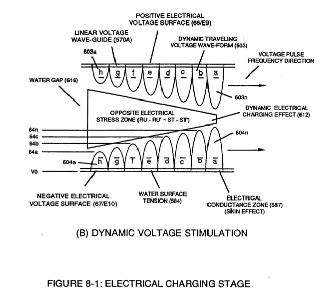](https://stanslegacy.com/uploads/images/gallery/2023-12/A45vcZgK91mbYaWL-image-1702960908921-41-46.png) | **Figure (1-17)** [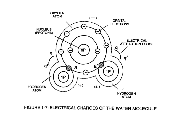](https://stanslegacy.com/uploads/images/gallery/2023-12/qjHD3ylYfSe8Kjxq-image-1702960829872-40-27.png) |
| [](https://stanslegacy.com/uploads/images/gallery/2023-12/ZJecZJOhMgcfhbEH-image-1702958533456-02-11.png) | [](https://stanslegacy.com/uploads/images/gallery/2023-12/N1lvKB5LMDkYXTCf-image-1702958618091-03-36.png) |
| [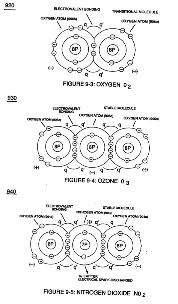](https://stanslegacy.com/uploads/images/gallery/2023-12/FNwXOxBf1UGR2m3h-image-1702958634474-03-52.png) | [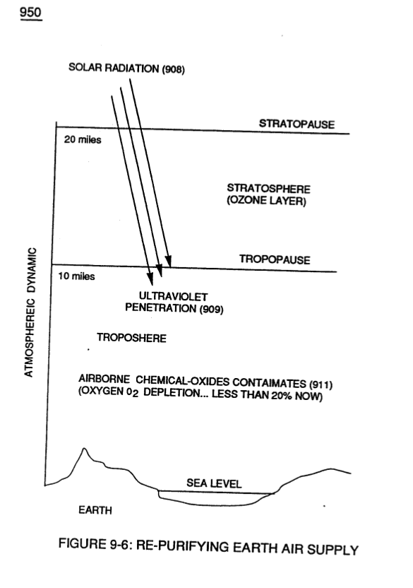](https://stanslegacy.com/uploads/images/gallery/2023-12/sZvRN0capAVHxdfE-image-1702958642386-04-00.png) |
| [](https://stanslegacy.com/uploads/images/gallery/2023-12/iHgtBiWb3NTMeF3W-image-1702958650292-04-08.png) |
Is "**Particle Oscillation**" as a "**Energy Generator**" the way to tap into this universal energy source to fuel our economy?
And if so, by what means?The WFC Technique of "**Easer**" is, now, open for scientific dissertation ... and is explained in the following way:
> In the annals of scientific endeavors, the prior art only subscribed in using the following scenarios to cause "**Particle Oscillation**" as a "**Energy Generator**": > > particle impact to produce kinetic energy; > > current flow to manifest light energy by which we see from an incandescent light bulbs; > > electromagnetic flux-energy to ionize gases inside an fluorescent tube exposed to an electrical power line; > > photon energy absorption to activate a laser device by the use of a strobe light; > > chemical stress to cause combustion by rearranging molecular structures; > > redirecting and splitting light transmission through optical prismatic structures, and the atomic absorption and re-radiation of acoustical energy for sound-box amplification. > > In reference to **WFC Technology of Inventions**, "**Electrical Stress**" propagated by "**Opposite Voltage Polarity**" is utilized as a "**New**" way to cause "**Particle Oscillation**" as a "**Energy Generator**" > > ... giving way to "the **Birth of New Technology**" > > ... such as, "**The Optical Thermal Lens**" called "**Easer**" > > ... tapping into "**Universal Energy**" via "**Voltage Tickling of State Space**" under **resonant conditions**. # Propagating Electrical Stress As in reference to **WFC Patent Validation Report** dated January 14, 1983 as per **WFC Test-Results** "Mode of Operability" of using "**Voltage Potential**" to "**Dissociates the Water Molecule**" by way of the "**Electrical Polarization Process**" (160) of Figure (3-26) as so specified under U.S. Patent Law (35 USC 101) demonstrate operability, the applied **Pulse-Voltage Frequency** is adjusted to tune-in to the dielectric properties of water by the use of WFC "**Amp Inhibiting Circuit**" (970) of Figure (10-1), as further illustrated in **WFC Tech-Brief** titled "**The Birth of New Technology**" > ... U.S. Patent Memos 420 - 428, including "Table of Tabulation" > (Appendix A) as to "Glossary of Application Notes" (Appendix B). The **Amp Inhibiting Circuit** (970) of Figure (10-1) as to (690) of Figure (7-8) is composed of two copper wires "**Bifilar**" wound (wrapped) about a magnetic induction core to allow amp restriction (minimizing current leakage) while encouraging "**Voltage Potential**"(Va xxx Vn) across the water molecule to perform WFC "**Electrical Polarization Process**", as so illustrated in Figure (7-1) [WFC memo (426)](https://stanslegacy.com/books/the-birth-of-new-technology/chapter/wfc-426-vic-matrix-circuit "WFC 426 - VIC Matrix Circuit") titled **VIC Matrix Circuit**.| **Amp Inhibiting Circuit** (970) of Figure (10-1) [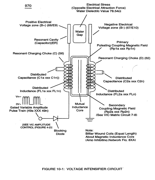](https://stanslegacy.com/uploads/images/gallery/2023-12/0YUyJtuQKZZq8D5H-image-1702939521353.png) | (690) of Figure (7-8) [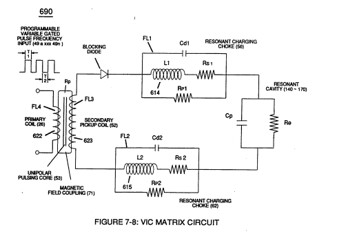](https://stanslegacy.com/uploads/images/gallery/2023-12/ZT3njPCTon79enNm-image-1702939728729.png) |
| "**Resonant Charging Choke**" (56) of Figure (7-1) [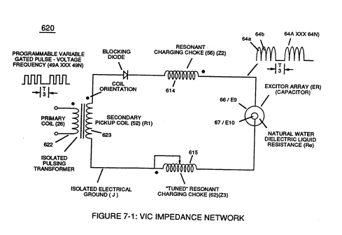](https://stanslegacy.com/uploads/images/gallery/2023-12/Mghp15gu0NRex7m6-image-1702939783175.png) | **self-inductance** (640) of Figure 7-3B) [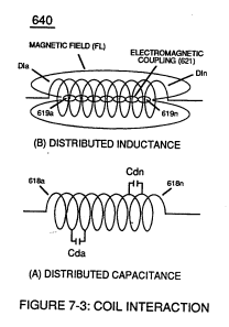](https://stanslegacy.com/uploads/images/gallery/2023-12/BMbDaBaTU2RN2uZi-image-1702939800001.png) |
... thereby, preventing amp "in-fluxing" (discouraging electron arc over) across **Dielectric Capacitor Gap** (ER)(66/67) while **Electrical Stress** (ST-ST' - RU-RU') of **Opposite Voltage Polarity** (B+/B-) brings on **Energy Priming Stage** (520) of Figure (5-3) which is refer to, herein, as "**Voltage Tickling of State Space**."
| **Energy Priming Stage** (520) of Figure (5-3) [](https://stanslegacy.com/uploads/images/gallery/2023-12/60fKlYumsAqhz4DV-image-1702942966128.png) |
| **Amp Inhibiting Circuit** Figure (10-1) [](https://stanslegacy.com/uploads/images/gallery/2023-12/0YUyJtuQKZZq8D5H-image-1702939521353.png) | Figure (10-3 A/B) [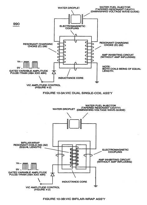](https://stanslegacy.com/uploads/images/gallery/2023-12/KXhbKB5X4AfEU0Lz-image-1702942909160.png) |
To reduce amp leakage still further, the copper wire of both **Resonant Charging Chokes** (56/62) can be replaced with a magnetically inductive stainless steel wire (430F/FR) having a resistive value (Ohms) to the flow of electrons while taking on the capacitance and inductance characteristic of a coil wire.
VIC **Bifilar Wrap Coil-Assembly** (10-3B) and VIC **Dual Coil Wrap-Assembly** (10-3A) both utilize either "E" & “I” and "U" Inductance Core configurations to concentrate Mutual Inductance Fields (Rpl/Rp2) in order to optimize **Amp Inhibiting Process** (750) of Figure (7-14).
[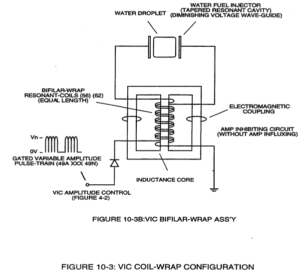](https://stanslegacy.com/uploads/images/gallery/2023-12/GohHkqjrGXbkNPrN-image-1702939496250.png)"E" “I” core shape (10-3B) is **most preferable** since amp spike surge is minimize during repetitive pulsing operations.
[](https://stanslegacy.com/uploads/images/gallery/2023-12/0YUyJtuQKZZq8D5H-image-1702939521353.png)Beyond amp restricting characteristic of said **Amp Inhibiting Circuit** (970) of Figure (10-1) as to **Voltage Intensifier Circuit** (60) of Figure (3-22), the spiral-wrapped coils (**Resonant Charging Chokes** 56/62) being paired together, also, causes voltage level enhancement beyond applied voltage input since the "**Distributed Capacitance**" (C1a xxx C1n - C2a xxx C2n) / "**Distributed Inductance**" (FL1a xxx FL1n - FL2a xxx FL2n) of said "bifilar" wrapped coils (Figure 7-3) as to (990) of Figure (10-3) encourages the compounding effect (increasing magnetic field-strength during each pulsing cycle) of electromagnetic field-strength (Rp1a xxx Rp1n - Rp2a xxx Rp2n) (mutual induction) when applied **Pulse-Voltage** frequency (49a xxx 49n) of Figure (3-34) passes through the positive energized **Resonant Charging Choke** (56).| Figure (3-34) [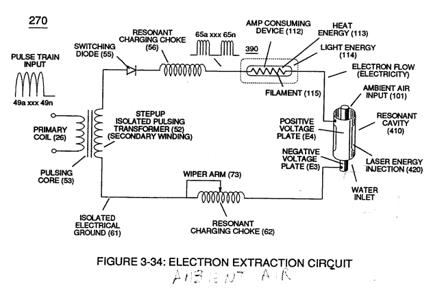](https://stanslegacy.com/uploads/images/gallery/2023-12/qoVW6HIjttBMvrdg-image-1702939372308.png) | **Voltage Intensifier Circuit** (60) of Figure (3-22) [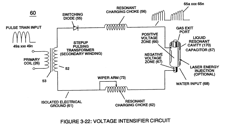](https://stanslegacy.com/uploads/images/gallery/2023-12/NSjdNz4Z6RhRXKyL-image-1702939423197.png) |
| **"bifilar" wrapped coils (Figure 7-3)** [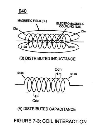](https://stanslegacy.com/uploads/images/gallery/2023-12/AOkHCY1RG0JAkGGV-image-1702939459667.png) | **(990) of Figure (10-3)** [](https://stanslegacy.com/uploads/images/gallery/2023-12/GohHkqjrGXbkNPrN-image-1702939496250.png) |
Furthermore, the paired coil-wires opposite voltage potential \[**positive electrical attraction force** (B+) - **negative electrical attraction force** (B-)\] \[hereinafter called **Electrical Stress** (SS' - RR') as to (160) of Figure (3-26)\] are always **equal** in electrical magnitude/intensity **since the wire-lengths of each coil** **are the same**.
| (160) of Figure (3-26) [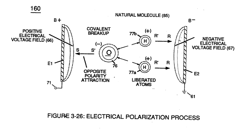](https://stanslegacy.com/uploads/images/gallery/2023-12/u0GhsFkpdntt3bvc-image-1702942493764.png) |
**Pulse-Voltage** repetition rate sets up the step-up charging effect Figure (1-3) since the "**Resonant Cavity**" (Cp) functions as a "**Capacitor**" (ER) due to the dielectric value of the liquid (or gases) which becomes an integral part of the **VIC Circuit**, as so illustrated in (650) of Figure (7-4).
[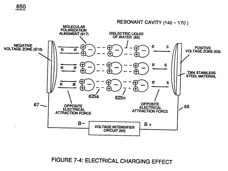](https://stanslegacy.com/uploads/images/gallery/2023-12/gvwO7lLymg5QDCCF-image-1702942582537.png)The resultant voltage enhancement (**Voltage Amplitude**) can *exceed 40 kilovolts* to instantly convert water (droplets) into thermal explosive energy (gtnt) on demand, as so illustrated in **Voltage Intensifier Circuit Diagram** (970) of Figure (10-1).
**[](https://stanslegacy.com/uploads/images/gallery/2023-12/0YUyJtuQKZZq8D5H-image-1702939521353.png)** **Blocking Diode** (52) of Figure (4-9) as to Figure (1-1) allows **unipolar pulse-wave** to go more positive on each pulse-cycle since the **Blocking Diode** (52) prevents the **Resonant Cavity** (Cp) from discharging during pulse off-time, as so illustrated in Figure (1-4) as to (60) of Figure (3-22)| **Blocking Diode** (52) of Figure (4-9) [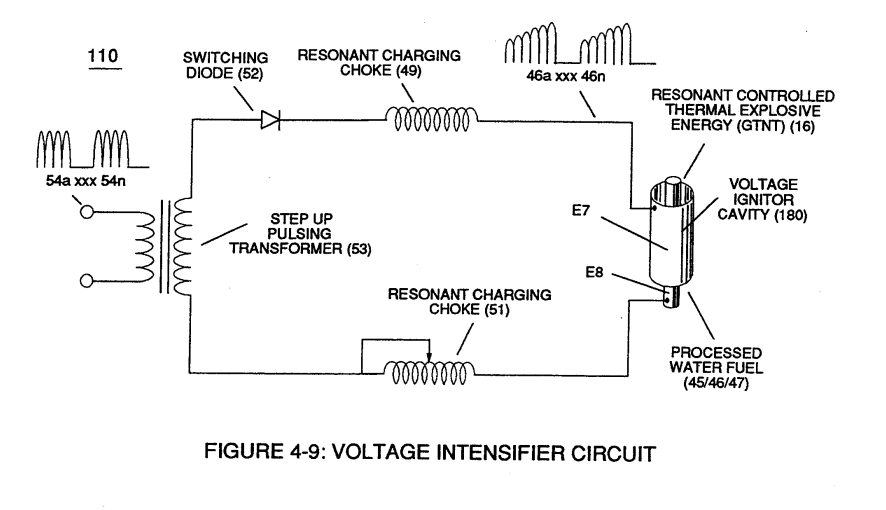](https://stanslegacy.com/uploads/images/gallery/2023-12/UUWbK3PTfcFQX1x5-image-1702942719974.png) | Figure (1-1) [](https://stanslegacy.com/uploads/images/gallery/2023-12/SKQ3lhwFMYNvXMGW-image-1702942745761.png) |
| **Figure (1-4)** [](https://stanslegacy.com/uploads/images/gallery/2023-12/SgHtDkV4j5pRs7ws-image-1702942767454.png) | (60) of Figure (3-22) [](https://stanslegacy.com/uploads/images/gallery/2023-12/Pn4vejGyLzXDQAka-image-1702942693073.png) |
| Figure (5-1) [](https://stanslegacy.com/uploads/images/gallery/2023-12/xaTVEqFGT7fB4FVF-image-1702942202139.png) | Figure (5-2) [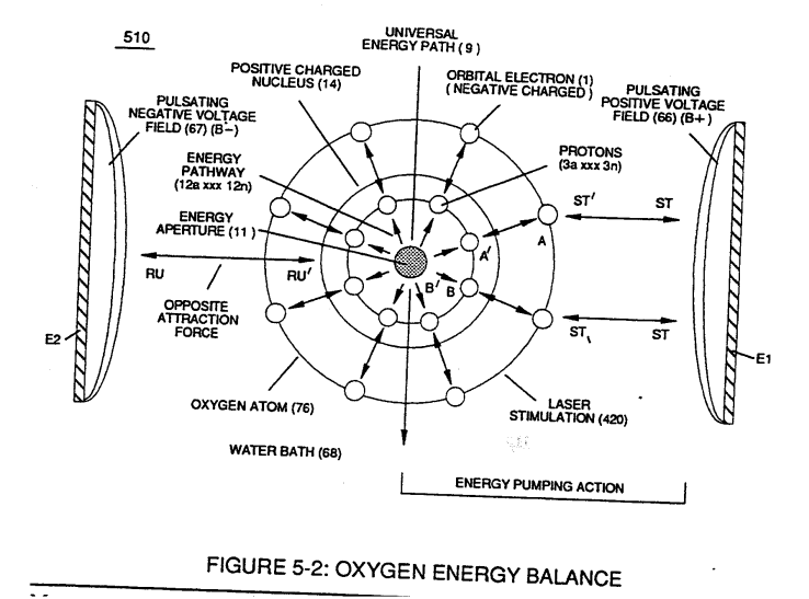](https://stanslegacy.com/uploads/images/gallery/2023-12/kKAfASozuQVjrADV-image-1702785002972.png) |
The programmable pulse-frequency (49a xxx 49n) of Figure (10-1) input is simply adjusted to tune-in to the dielectric property of the **Water Molecule**.
The resultant **Dynamic Electrical Charging Effect** (612) of Figure (8-1) acts as a progressive energy enhancer (**Energy Priming Stage**) (500) of Figure (5-1)| **Dynamic Electrical Charging Effect** (612) of Figure (8-1) [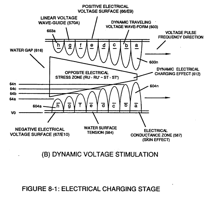](https://stanslegacy.com/uploads/images/gallery/2023-12/jbE7xDLZED0syEvn-image-1702942166357.png) | **Energy Priming Stage** (500) of Figure (5-1) [](https://stanslegacy.com/uploads/images/gallery/2023-12/xaTVEqFGT7fB4FVF-image-1702942202139.png) |
| **Static State Space** (790) of (8-3) [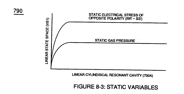](https://stanslegacy.com/uploads/images/gallery/2023-12/79jfPp35lIj536Tg-image-1702942388172.png) | **Dynamic State Space** (800) of Figure (8-4) [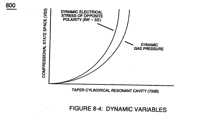](https://stanslegacy.com/uploads/images/gallery/2023-12/LJTBdQOkTdGKfIIe-image-1702942399614.png) |
| **Voltage Rippling Effect** (1010) of Figure (10-5) [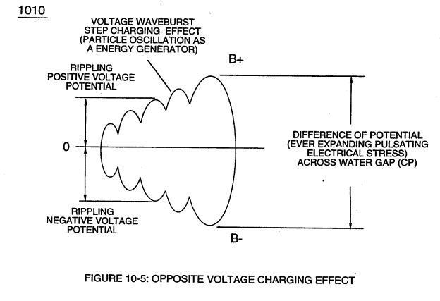](https://stanslegacy.com/uploads/images/gallery/2023-12/2gF5TutyP4njH8pH-image-1702783749893.png) | **Dynamic Voltage** **Stimulation** (770B) of Figure (8-1) |
| (580) of Figure (6-1) [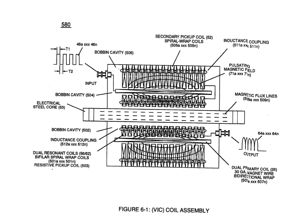](https://stanslegacy.com/uploads/images/gallery/2023-12/gXoCG7Kh63SOoH8j-image-1702955935044-18-52.png) |
| **Voltage Rippling Effect** (1010) of Figure (10-5) [](https://stanslegacy.com/uploads/images/gallery/2023-12/2gF5TutyP4njH8pH-image-1702783749893.png) | (280) of Figure (3-35) [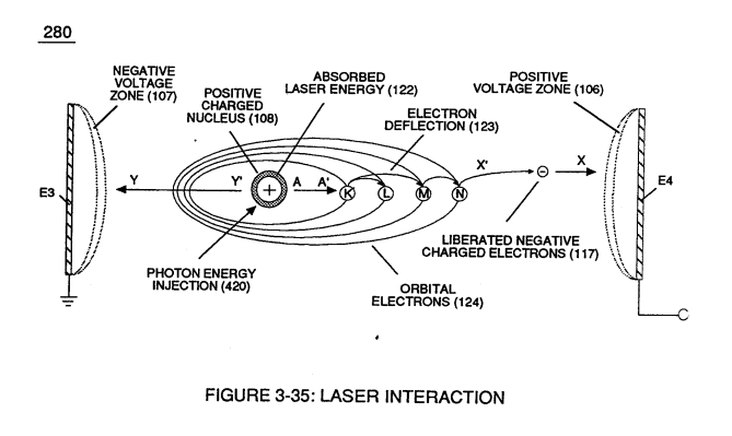](https://stanslegacy.com/uploads/images/gallery/2023-12/SsJfbfRuvrjvaX6S-image-1702783731051.png) |
The greater the **Electrical Stress** (RU-RU' a xxx ST -ST'n) applied (64B+/64B-a xxx 64B+/64B-), the greater amount of thermal explosive energy (16/gtnta xxx 16/gtntn) of Figure (6-2) as to (70) of Figure (4-5) is released from **Resonant Water Gap** (Cp) (970) of Figure (10-1), as further illustrated in (70) of Figure (4-5).
[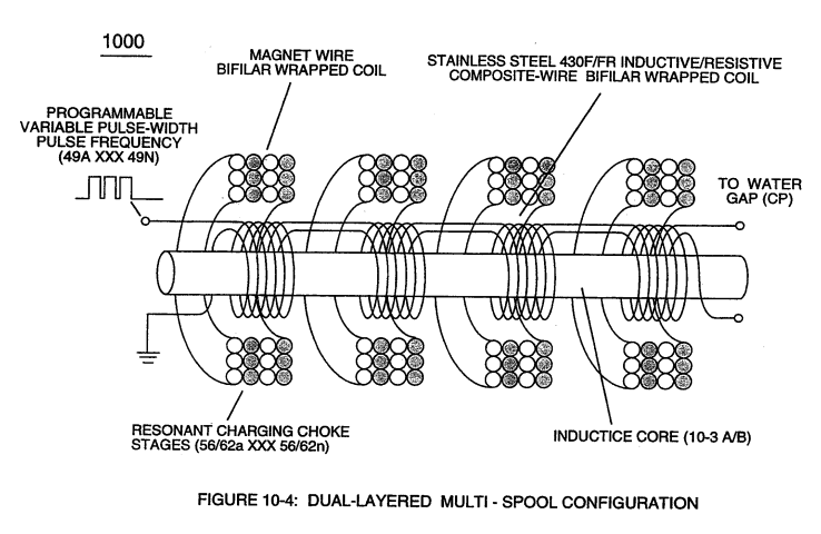](https://stanslegacy.com/uploads/images/gallery/2023-12/xe0ccm69rRxiZvuE-image-1702783906686.png)Increasing energy-yield (16/gtnt) still further (xxx 16/gtntnl+ 16/gtntn2 + 16/gtntn ... etc.) is accomplished by increasing the number of **Resonant Charging Choke Stages** (xxx 56/62n + 56/62n 1+ 56/62n2 + 56/62n ... etc. -S- xxx SS56/62n + SS56/62nl + SS56/62n2 + SS56/62n ... etc.) of Figure (10-4) in "**Sequential Order**" (-S-) since the total number of **Multi-Coil Magnet** bifilar coils (56/62a xxx 56/62n) serially electrically connected together are sequentially electrically linked to an equal number of serially electrically aligned **Stainless Steel Resonant Coils** (SS/56/62a xxx SS/56/62n) ... allowing each/both **bifilar coil assembly** (56/62a xxx 56/62n -S- SS56/62a xxx SS56/62n) to be electrically and magnetically energized **in the same progressive direction** toward **Water Gap** (Cp) and away from blocking diode (55) of Figure (3-34) as to Figure (10-1) and Figure (10-3)| Figure (10-1) [](https://stanslegacy.com/uploads/images/gallery/2023-12/0YUyJtuQKZZq8D5H-image-1702939521353.png) | Figure (10-3) [](https://stanslegacy.com/uploads/images/gallery/2023-12/KXhbKB5X4AfEU0Lz-image-1702942909160.png) |
| blocking diode (55) of Figure (3-34) [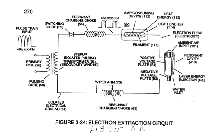](https://stanslegacy.com/uploads/images/gallery/2023-12/XKTFNQoga776I1dQ-image-1702956441259-27-18.png) | Figure (10-3A) [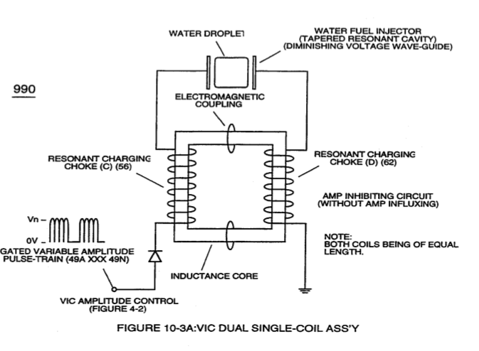](https://stanslegacy.com/uploads/images/gallery/2023-12/HjMjHDRfYjv7l7GF-image-1702956542374-28-59.png) |
| **Voltage** **Performance Graph** (750) of Figure (7-14) [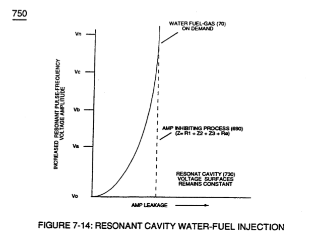](https://stanslegacy.com/uploads/images/gallery/2023-12/QkbBVeqDSccpltH5-image-1702956486877-28-03.png) | Figure (10-3B)  |
| **Voltage Intensifier Circuit (970) of Figure (10-1)** **[](https://stanslegacy.com/uploads/images/gallery/2023-12/0YUyJtuQKZZq8D5H-image-1702939521353.png)** | (620) of figure (7-1) [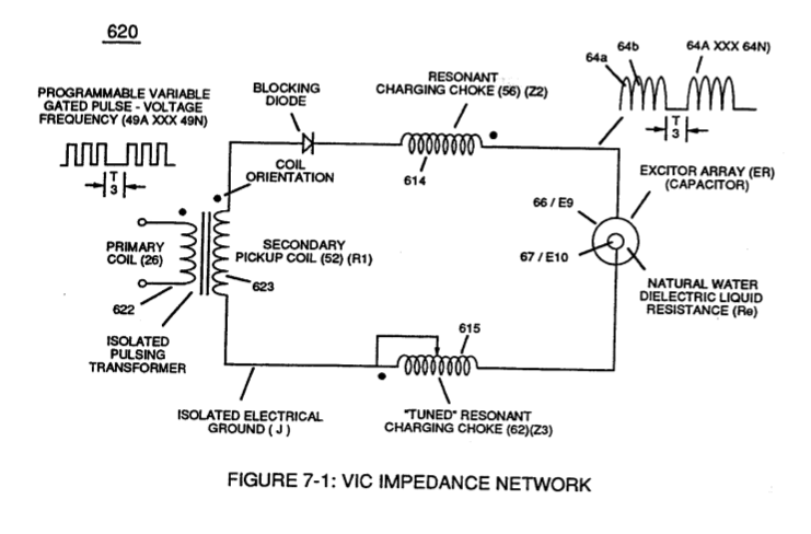](https://stanslegacy.com/uploads/images/gallery/2023-12/rPr7Y9kNflqVeu6r-image-1702956465289-27-39.png) |
| ... see **Dynamic Voltage Waveform** (770) of Figure (8-1), once again. [](https://stanslegacy.com/uploads/images/gallery/2023-12/jbE7xDLZED0syEvn-image-1702942166357.png) |
The magnet **Coil-Wire** (56/62) is best suited for **Voltage** inducement while the inductance/capacitance/resistance properties of **Stainless Steel coil-wire** (SS56-SS62) is appropriately used to **restrict electron movement** beyond the self-inductance of each energized coil when elevated voltage levels *(up to beyond 40 kilovolts*) are to be reached/obtained without experiencing any appreciable amount of "**Amp Influxing**."
Generally, magnet coil-wire length is longer than the Stainless steel coil-wire length and magnet bifilar-coil (56/62) is placed on top of **Stainless Steel bifilar-coil** (SS56/62) to maximize mutual inductance coil-field (Rp2) (adding Rp1+Rp2) of (690) of Figure (7-8) to cause coil capacitance (Cda xxx Cdn) to help maintain and even increase pulse voltage amplitude (xxx Vn + Vn 1 + Vn2 + Vn .... etc.) while the resistive value (Rs2) of SS Coil-Wire (SS56/62) performs the work of further resisting the flow of amps not inhibited by both self-Inductance fields (Rpl + Rp2), as so illustrated in (690) of Figure (7-8).| (690) of Figure (7-8) [](https://stanslegacy.com/uploads/images/gallery/2023-12/ZT3njPCTon79enNm-image-1702939728729.png) |
In all cases, bifilar coils (56/62 - SS56/62) are electromagnetically orientated **in the same direction**.
In terms of operability, electrically flexing (**Particle Oscillation**) the combustible atoms of the water molecule as a "**Energy Generator**" by way of opposite voltage polarity is extremely economical since voltage is not consumed in an electronic circuit.
**[](https://stanslegacy.com/uploads/images/gallery/2023-12/0YUyJtuQKZZq8D5H-image-1702939521353.png)Amp Inhibiting Circuit** (970) of Figure (10-1) restricts/inhibits amp flow to a minimal level while elevating "**Difference of Potential**" to the highest possible level. The greater the "**Difference of Potential**" (in this case, electrical stress) the greater amount of work is performed ... thereby, being in compliance with the **Laws of Physics** since atoms are the source of all energy in our physical universe and atoms are directly responsive to / stimulated by external electrical forces. # Optical Thermal Lens When unexcited matter (**quiescent state**) is stimulated into an excited state (**active state**) by way of "**Electrical Stress**", a new form of **thermal-energy** (Ers) release is possible beyond gas combustion stage (gtnt) by the use of **WFC Optical Thermal Lens**; as so illustrated in (980) of Figure (10-2). [](https://stanslegacy.com/uploads/images/gallery/2023-12/tZNzZ8NZhhL36N0t-image-1702943462806.png) **Water Cap** (Cp) is, now, transformed into **Vacuum Cavity** (Vc) where only hydrogen atoms in a fluid medium is exposed to **Voltage Zones** (ER) ... forming **Capacitor Gap** (Cv) since the gas medium, so exhibits a dielectric value and amp in-fluxing (prohibiting amp leakage into and away from **Capacitor Vacuum-Gap** (Cv)) is held to a minimum due to the bifilar wrapped resonant-coils (56/62). **The Energy Pumping Stage** (520) of Figure (5-3) as to (500) of Figure (5-1) attenuates the hydrogen energy aperture (7) of (550) of Figure (5-8) when applied **Opposite Voltage Potential** (Va xxx Vn) (49a xxx 49n) (B+/B-) produces pulsating **Electrical Stress Wave-form** (opposite electrical attraction force) (RU/RU' - ST/ST'a xxx RU/RU' ST/ST'n) during **Pulsing Operations**.| **The Energy Pumping Stage** (520) of Figure (5-3) [](https://stanslegacy.com/uploads/images/gallery/2023-12/60fKlYumsAqhz4DV-image-1702942966128.png) | (500) of Figure (5-1) [](https://stanslegacy.com/uploads/images/gallery/2023-12/xaTVEqFGT7fB4FVF-image-1702942202139.png) |
| hydrogen energy aperture (7) of (550) of Figure (5-8) [](https://stanslegacy.com/uploads/images/gallery/2023-12/nqKy7uoy8YFV4TZX-image-1702943867338.png) |
**The Vacuum Chamber** (Cv) containing the hydrogen gas atoms is composed of a high temperature **quartz material** (918) while **Voltage Zones** (ER) becomes **Voltage Wave-Guides** (770) of Figure (8-1) by the use of chemically inert T304 stainless steel material
... forming **Electrical Conductance** **Zones** (Skin Effect) (587)... allowing unipolar **Voltage Pulse-waves** (583/602axxx 583/602n) of Figure (8-1A) to travel the linear length of the **Voltage Wave-Guide**.
The **Static Electrical Charging Effect** ( -) (585) is set up when applied **Electrical Stress Wave-form** (RD / RD' - ST / ST') is simultaneously applied on opposite sides of the hydrogen atoms ... propagating "**Particle Oscillation**" as a "**Energy Generator**" in a vacuum rather than by chemical interaction (chemical stress) of gas combustion (gtnt). # Quartz Tube Configuration & Operational Parameters [](https://stanslegacy.com/uploads/images/gallery/2023-12/U57AzrkN0QiAqnFe-image-1702951076805.png)Exposing the hydrogen atoms to applied **Static Voltage Stimulation** (770) of Figure (8-1) causes the **Static Electrical Charging Effect** (585) to set up "**Voltage Tickling of State Space**" which takes the hydrogen atom (s) from "**Quiescent State**" (Qs) to "**Active State**" (As) and then back again to "**Quiescent State"** (Qs) once applied unipolar pulse-wave (583/602) goes through **Voltage Pulsing Cycle** (Vpwf) from "**Ground State**" (Gs) to **Voltage Peak potential** (Vpp) (780) of Figure (8-2A) and then returns to "**Ground State**" (Gs) for continued repetitive **Voltage-Pulsing** (583/602a xxx 583/602n) ... forming **Pulse Wave Frequency** (Pwf), as so illustrated in (780) of Figure (8-2) as to (770) of Figure (8-1). [](https://stanslegacy.com/uploads/images/gallery/2023-12/G2ExBnm1UDBVjB9T-image-1702951052810.png)The resultant **Flex-Density** (Fd) of the hydrogen atom(s) is, now, directly related to applied **Voltage Amplitude** (64a - 64b - 64c - 64n) of Figure (8-2A) which directly determines the **Field Strength** (Fs) of **Static Electrical Charging Effect** (Sece)(585). The **Voltage Pulse Field** (Vpf) (forming leading and trailing edges of each **Voltage Pulse**) determines the duration of the **Static Electrical Charging Effect** (Sece) being superimposed onto the **Hydrogen Atom** (s) during each **Voltage Pulsing Cycle** (Vpwf).The **Electrical Conduction Zone** (587) (Skin Effect) between the dielectric gas medium (919) and the **Electrical Contact Surface** of the inside surface area of the **Voltage Wave-Guides** (66/67) allows **Unipolar Pulse Train** (583a/602a-583b/602b - 583n/602n) to travel the entire length of the **Voltage Wave Guides** that make up **Voltage Zones** (66/E9 – 67/E10).
[](https://stanslegacy.com/uploads/images/gallery/2023-12/3MyVhVHoWtFQcfah-image-1702951265668.png) **Static Voltage Stimulation** (770) of Figure (8-1A) is where **Voltage Peak Potential** (Vpp) remains constant during **Voltage Pulse Formation** (VpbNpa) to keep reforming **Flex-Density Potential** (Fdpa xxx Fdpn) from going beyond a certain point away from **Static State of Equilibrium** (Esse) \[*Quiescent State of the hydrogen atom (s)*\]; whereby,**Dynamic Voltage Stimulation** (770) of Figure (8-1B) continues to go farther and farther away from the **State of Equilibrium** (Esse) during each and every **Voltage Pulsing Cycle** (Vpf), as so illustrated in (770) of Figure (8-1B}
[](https://stanslegacy.com/uploads/images/gallery/2023-12/cana1yDIleGXdxsp-image-1702951294504.png) ... establishing variable **Dynamic Electrical Charging Effect** (612). In both cases, **Static Voltage Stimulation** (770) of Figure (8-1A) and **Dynamic Voltage Stimulation** (770) of Figure (8-1B) incorporates the use of **Positive Electrical Voltage Potential** (B+) (Ell) and **Negative Electrical Voltage Potential** (B-) (EI2) to form synchronized diametrically opposed **Voltage Gate-Pulse** (Vgp) (583/602) across **Vacuum Gap** (Vc) ... thereby, establishing functional parameters of **Optical Thermal Lens** (980) of Figure (10-2) when **Voltage Intensifier Circuit** (VIC Circuit) (10-1) is electrically connected to **Voltage Zones** (ER) (66/Ell-67/E12). [](https://stanslegacy.com/uploads/images/gallery/2023-12/tZNzZ8NZhhL36N0t-image-1702943462806.png)Remember, **Voltage-Sync Gate-Pulse** (Vgp) produces opposite electrical attraction forces (B+/ST-ST' - B-/RU-RU') of Figure (5-1) that are not consumed in an electronic circuit.
# A Technique Called "Easer" **Energy Priming Stage** (500) of Figure (5-1) is, now, activated and performed when the hydrogen atom (s) is exposed to applied **Voltage-Sync Gate Pulse** (Vgp) by which **Electrical Voltage Attraction Forces** (Electrical Stress) (RU-RU' - ST-ST') causes "**Particle Oscillation**" of the hydrogen atom (s) to **emit radiant energy** (Ers) (919), as so illustrated in (980) of Figure (10-2) as to (500) of Figure (5-1).| (980) of Figure (10-2) [](https://stanslegacy.com/uploads/images/gallery/2023-12/tZNzZ8NZhhL36N0t-image-1702943462806.png) | (500) of Figure (5-1) [](https://stanslegacy.com/uploads/images/gallery/2023-12/xaTVEqFGT7fB4FVF-image-1702942202139.png) |
... whereby, **atomic electrical attraction force** (4) that exists between the deflected orbital **negative charged electron** -(1) and the pivotal positive charged **Proton** (3) is attenuated (∆4a xxx ∆4n - ∆5a xxx ∆5n)
... which, in turns, attenuates the spin-velocity of the "**Gyroscopic Regulator**" of the hydrogen nucleus to cause **Energy Aperture** (7) to emit/transmit more or greater amount of **Universal Energy** (9) *into, through, and beyond* the energy spectrum of the hydrogen atom for "**Energy Propagation**" (atoms being an "**Energy Generator**" in our physical universe) by way of "**Particle Oscillation**" of the hydrogen atom (or any other atom), as so illustrated in (570) of Figure (5-10) as to (550) of Figure (5-8).| (570) of Figure (5-10) [](https://stanslegacy.com/uploads/images/gallery/2023-12/nUNJwiZoZa4CO5Te-image-1702521046706.png) | (550) of Figure (5-8) [](https://stanslegacy.com/uploads/images/gallery/2023-12/pO1E1NbCBxICDUBv-image-1702520739603.png) |
(Vpp) **not only** determines on how far the deflected orbital electron will move away from the pivotal proton during "active state" **but, also**, is directly related to **Flex-Density** (Fd) of the hydrogen atom
... **Flex-Density** (Fd) being the measure of energy-intensity (**Wavelets of energy**) emitted/released from the oscillatory hydrogen atom (undergoing particle oscillation) in proportional relationship to the field strength/intensity of the external **electrical stress-force** (Est) superimposed onto the electrical field strength (AA' -ZZ') of Figure (5-3) of the hydrogen atom in "**Quiescent State-Space**" (Qss)| electrical field strength (AA' -ZZ') of Figure (5-3) [](https://stanslegacy.com/uploads/images/gallery/2023-12/YtLNv2CN4ytT1k3y-image-1702949578313.png) |
Going from "**Quiescent State-Space**" (Qss) to "**Active State-Space**" (Ass) and returning to "**Quiescent State-Space**"(Qss) once again for repetitive "**State Change**" beyond the "**State Condition**" of **Equilibrium** (Esse) in a given/predetermined unit of time (d time) is, herein, called "**Voltage Tickling of State Space**."
The greater the **electrical stress force** (xxxEsfn) per (-) **Voltage Gate-Pulse** (Esf- V gpa xxx Esf- V gpn) applied, the greater amount of **Flex-Density** (xxx Fdn) of **electromagnetic radiant energy** (917 a xxx 917) of Figure (10-2) per cm3 occurs.
[](https://stanslegacy.com/uploads/images/gallery/2023-12/ZT3njPCTon79enNm-image-1702939728729.png)Once the hydrogen atom "absorbs" a sufficient amount of **Universal Energy** (Ue)(9a-9b-9c- 9n) within the atom energy spectrum, the deflected electron (15) that have ~ to a higher energy state (activated state) (K to L orbit or beyond) **suddenly jumps back** to its original lower energy state (quiescent state) (back to K orbit) when **Input Pulse Frequency** (49) terminates **Voltage-Sync Pulse** (Vsp) during applied pulse off-time (T2) of Figure (7-8)... causing **spontaneous emission of coherent energy** (919) of Figure (10-2) to be emitted from partially transparent end plate (916) as long as positive pulse "on-time" (Tl) of Figure (7-8) continues.
[](https://stanslegacy.com/uploads/images/gallery/2023-12/tZNzZ8NZhhL36N0t-image-1702943462806.png) The **Radiant-Intensit****y** (Rei) of the **coherent wave-energy** (919) being released from the **quartz tube** (918) is, further, enhanced when **emitted energy-wavelets** (Ers) given off by the activated hydrogen atom are allowed to oscillate (back and forth movement) at an ***ever increasing*** "difference of potential" between the end plates (915/916).Together but in separate variable forms, **Applied Voltage Peak Potential** (Vpp),**Voltage Pulse Cycling** (49a xxx 49n), and **Opposite Voltage Potential** (Vgpa xxx Vgp) forming **Voltage Sync-Pulse** (49-Vpp-Vgpa xxx 49-Vpp-Vgpn) determines the **energy-intensity** (Eie) of the **coherent-beam** (919).
**Focusing lens** (921) is simply used to redirect the **Radiant-Energy** (917) to a **heat diffuser** (923) capable of converting **Radiant-Energy** (917) to heat energy for industrial usage.
The stimulated spontaneously emission of electromagnetic radiation from the hydrogen atom (or other atoms) by way of "**Electrical Stress**" is, hereinafter, called "**Easer**."
# WFC 429 - Illustrations| [](https://stanslegacy.com/uploads/images/gallery/2023-12/37BfoICFIwBz5Q3Z-image-1702699882471-11-19.png) | [](https://stanslegacy.com/uploads/images/gallery/2023-12/7jK40QIIH0QL6J01-image-1702699894355-11-32.png) |
| [](https://stanslegacy.com/uploads/images/gallery/2023-12/LnaKuGNd3S4E6Iv7-image-1702699906570-11-44.png) | [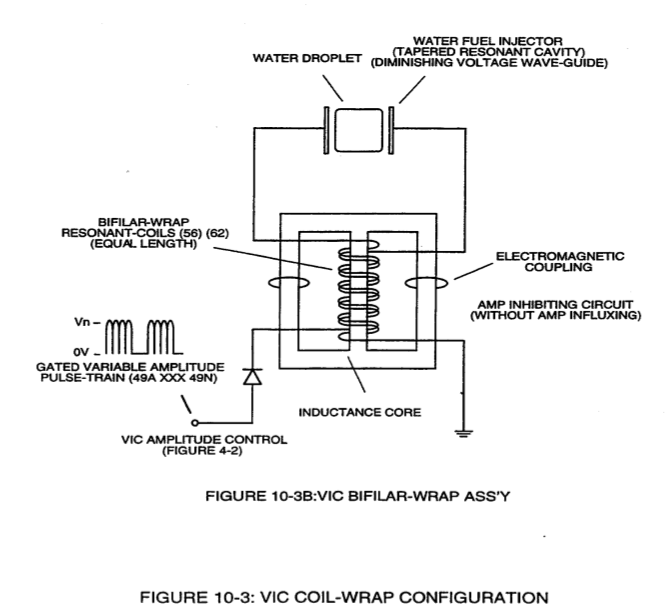](https://stanslegacy.com/uploads/images/gallery/2023-12/WFhslSxIU6keZXk9-image-1702699923570-12-01.png) |
| [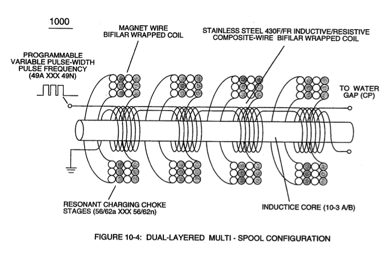](https://stanslegacy.com/uploads/images/gallery/2023-12/pO9IEOY9FXRjKIDb-image-1702699934560-12-12.png) | [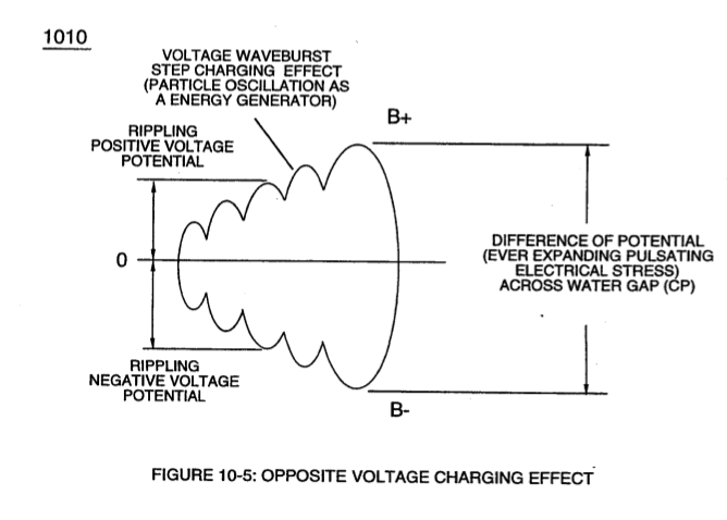](https://stanslegacy.com/uploads/images/gallery/2023-12/ZTcxcXzxOaO6W8pd-image-1702699942573-12-20.png) |
| **dual unipolar voltage pulse circuit** (1010) of Figure (11-1) [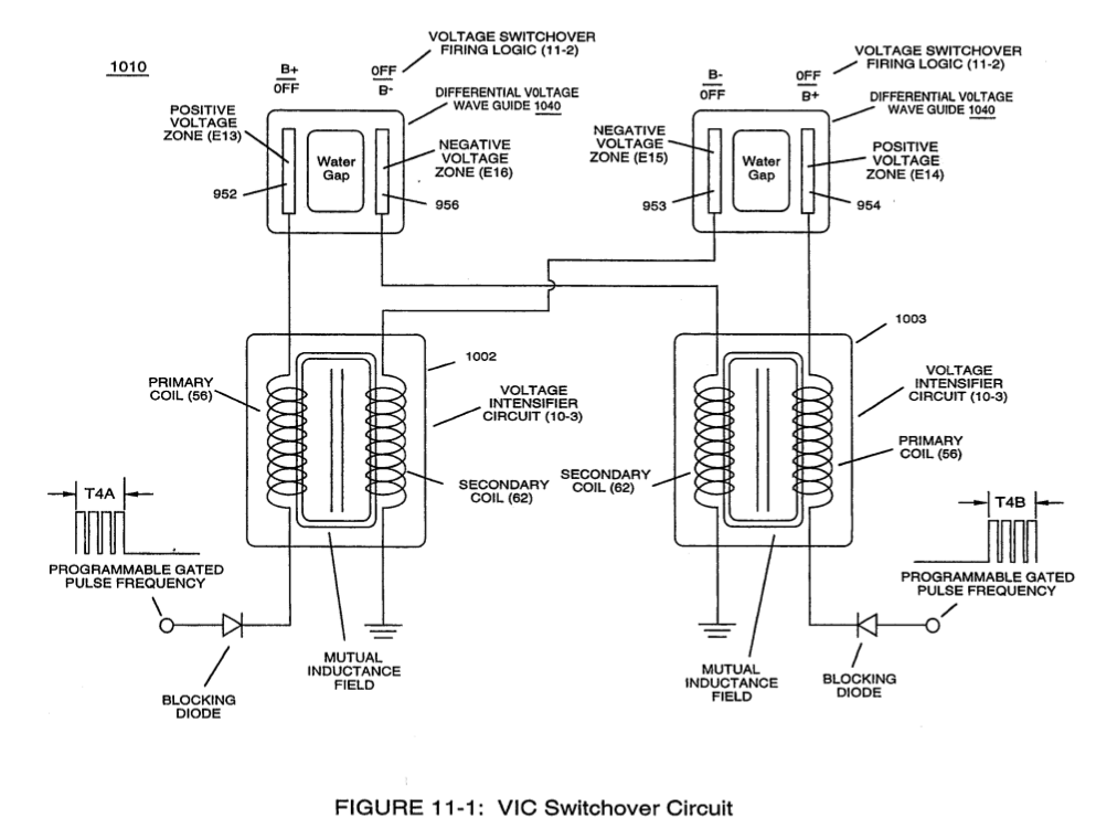](https://stanslegacy.com/uploads/images/gallery/2023-12/HcBIfVLeIWv0w3XL-image-1702703106211-05-03.png) | bipolar electrically charged water molecule (210) of Figure (3-46) [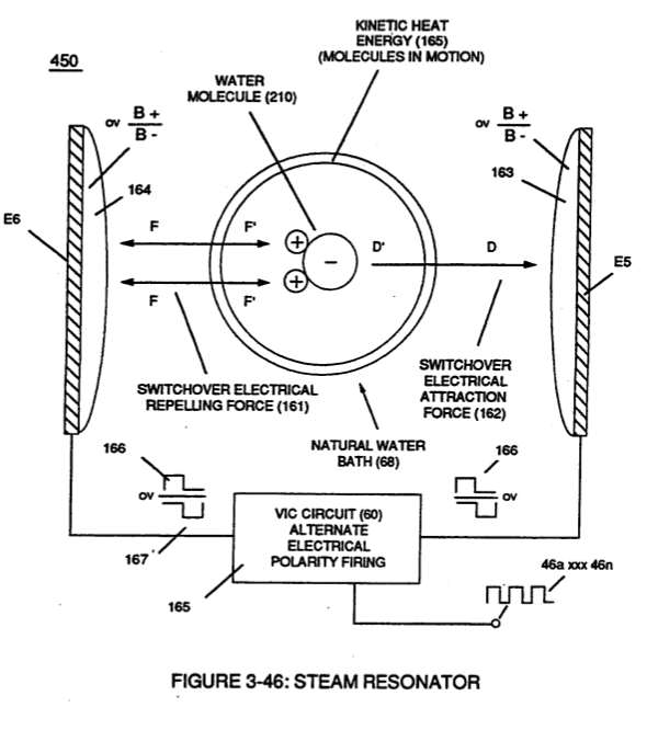](https://stanslegacy.com/uploads/images/gallery/2023-12/AZNAM1FWocGf3iEl-image-1702703660347-14-18.png) |
| energy aperture (7) of Figure (5-1) [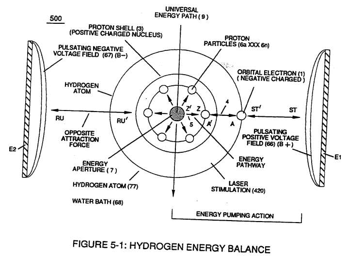](https://stanslegacy.com/uploads/images/gallery/2023-12/RsTc4XIzChLNVTTy-image-1702789250051.png) |
| (1030) of figure (11-3) [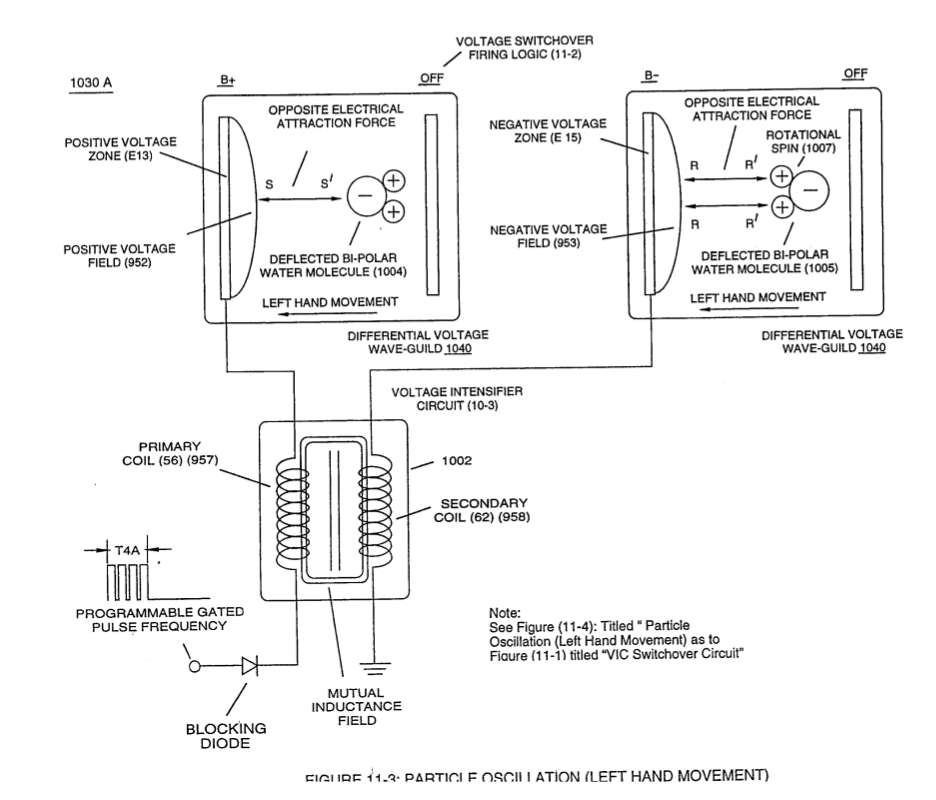](https://stanslegacy.com/uploads/images/gallery/2023-12/rnbV8J5BtkPBnkGc-image-1702703139186-05-36.png) |
... **disrupting the spin-velocity** of water molecule atom (s) orbiting electrons (s)
... forcing energy **Apertures** (7) of both unlike atoms of the water molecule (500) of Figure (5-1) and (510) of Figure (5-2) to be momentarily enlarged to a greater size (**Particle flexing** called hereinafter **Particle Oscillation**), separately but simultaneously| (500) of Figure (5-1) [](https://stanslegacy.com/uploads/images/gallery/2023-12/gfiUGqqBg9nYr8Vd-image-1702784991869.png) | (510) of Figure (5-2) [](https://stanslegacy.com/uploads/images/gallery/2023-12/kKAfASozuQVjrADV-image-1702785002972.png) |
| "**Voltage Energized Thermal Transference Effect**" (1050) of Figure (11-5) [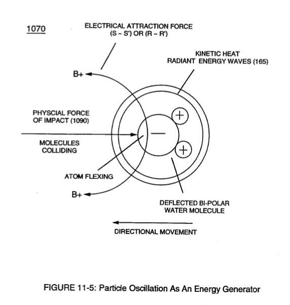](https://stanslegacy.com/uploads/images/gallery/2023-12/l7FHzfivBWPFCZwi-image-1702703159427-05-56.png) | gated pulse-voltage waveform (1020) of Figure (11-2) [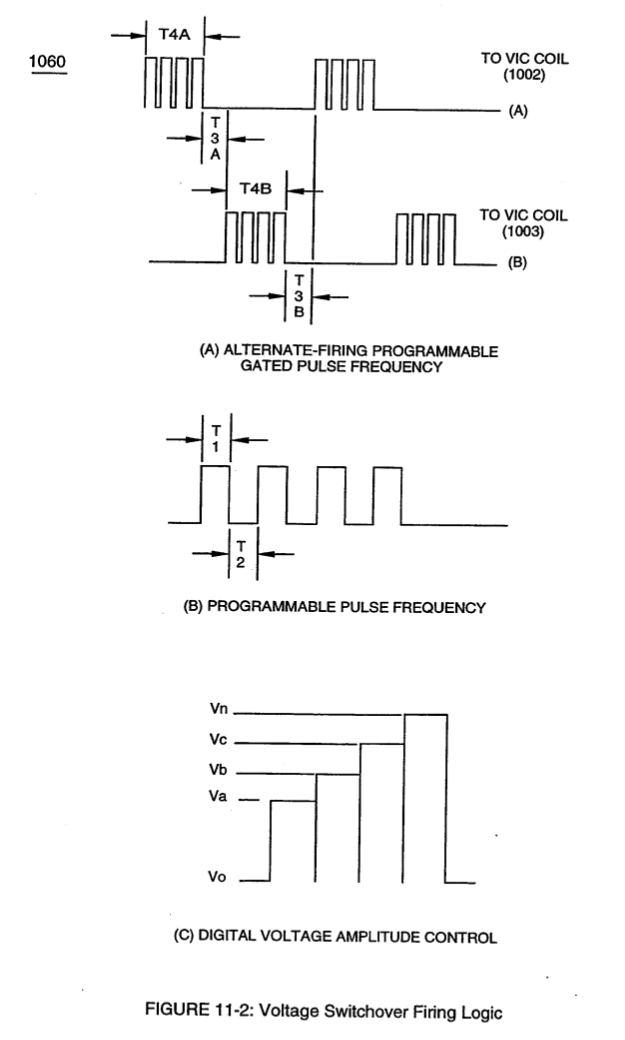](https://stanslegacy.com/uploads/images/gallery/2023-12/NKly51g38dfTrhao-image-1702703125291-05-22.png) |
| **VIC Switchover Circuit** (1010) of Figure (11-1) [](https://stanslegacy.com/uploads/images/gallery/2023-12/HcBIfVLeIWv0w3XL-image-1702703106211-05-03.png) | (1030) of Figure (11-3) [](https://stanslegacy.com/uploads/images/gallery/2023-12/rnbV8J5BtkPBnkGc-image-1702703139186-05-36.png) |
| [](https://stanslegacy.com/uploads/images/gallery/2023-12/Mncv7pHqilpxijdk-image-1702709662692-54-19.png) | [](https://stanslegacy.com/uploads/images/gallery/2023-12/Bnudcv0iW31thkrp-image-1702709674036-54-31.png) |
| (T4A) of Figure (11-2) [](https://stanslegacy.com/uploads/images/gallery/2023-12/NKly51g38dfTrhao-image-1702703125291-05-22.png) | **primary input coil** (957) of Figure (11-3) [](https://stanslegacy.com/uploads/images/gallery/2023-12/rnbV8J5BtkPBnkGc-image-1702703139186-05-36.png) |
Whereas, in like manner and in the same instant of time, stationary **negative voltage field** (958) attracts and displaces another and totally separate bipolar water molecule in an linear movement since **opposite electrical attraction force** (R-R') also exists between stationary **negative charged voltage plate** (953) and the, now, moving **positive charged hydrogen atom** (s) being electrovalently linked to the **negative charged atom**.
The resultant physical displacement (**physical movement**) of both separate bipolar water molecule moves relatively at the same displacement velocity since both particle masses of the water molecule (s) are basically identical in volume-size and the electrical intensity on both **stationary voltage fields** (952/953) are similar due to the fact that both **primary coil** (957) and **secondary coil** (958) comprising and forming **voltage intensifier circuit** (990) of Figure (10-3) are together bifilar wrapped in equal length.| **voltage intensifier circuit** (990) of Figure (10-3) [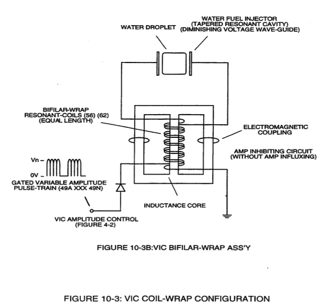](https://stanslegacy.com/uploads/images/gallery/2023-12/9wxofbF8mLrX1NsS-image-1702710087628-01-25.png) |
The simultaneous formation of both the **positive voltage field** (952) and the **negative voltage field** (953) is simply accomplished by the mutual electromagnetic inductance coupling field that is produced between the two bifilar wrapped coils (957/56 - 958/62) when the **primary coil** (957/56) is electrically energized by incoming **voltage pulse train** (T4a xxx T4n), as so illustrated in (970) of Figure (10-1).
| (970) of Figure (10-1) [](https://stanslegacy.com/uploads/images/gallery/2023-12/9wwfQqkZZ4BCEj3n-image-1702710774002-12-51.png) |
To **reverse direction** of the line of travel of the deflecting water molecule from **left-hand movement** to **right-hand movement**, another and completely separate **Voltage Intensifier VIC-Coil Assembly** (1003) of Figure (11-3) is periodically switched-on electrically by **alternate voltage pulse waveform** (T4B) once first voltage pulse wave-form (T4A) is terminated for a brief period of time (T3A)
... duplicating the **electrical attraction force** (S-S' !R-R') as before except ***both*** bipolar water molecule (s) (1004/1006) are, now, **redirected** and **deflected** in the opposite direction toward **voltage fields** (956/954), respectfully, as so illustrated in (1030) diagram (B) of Figure (11-3).This continued and repeated oscillation of the bipolar water molecule (1004/1006) in opposite direction of linear travel (back and forth motion) produces **kinetic energy** (165) when the moving and deflected bipolar water molecule (1004/1006) or any other bipolar molecule of water interlocking with ever changing **electrical attraction forces** (S-S' /R-R') collides with neighboring water molecules present in the same water bath (68).
Electrically interfacing alternate "**Switchover**" voltage pulse wave-form (T4A/T4B) to each of both **VIC Coil-Array** (s) (1002/1003) of Figure (11-3) as schematically depicted, now, forms **VIC Switchover Circuit** (1010) of Figure (11-1). Pairing together **positive voltage zone** (E13/952) with negative voltage zone (E16/956) and doing the same with voltage-surfaces (E14/953) to (E15/954) as so graphically shown in (1O1O) of Figure (11-1) and each having an longitudinal axis of identical length, now, individually forms what is called hereinafter a "**Differential Voltage Wave-guide**" (1040) ... being defined as heating water by alternate pulsation of opposite voltage fields at different pulse time-on periods, collectively called "**Voltage Switchover Firing Logic** (B+/O - B-/O - O/B - O/B+). In like manner as to **linear cylindrical resonant cavity** (730) of Figure (7-12), the **Differential Voltage Wave-Guide** (1040) of (1010) of Figure (11-1) as to Figure (11-6) is constructed in such a way as to allow a smaller tube to be placed inside a much larger tube having space relationship to allow water to pass there between, as so pictorially shown in (170) of Figure (3-25).The constructed tubular-Array is composed of T304 stainless steel material, or any equivalent thereof, which is chemically inert to the voltage deflecting process (lO50) of Figure (11- 5).
The electrical conductivity of the stainless steel material T304 and the dielectric properties of water (water being an insulator to the flow of amps) both together sets up **electrical conduction** **zone** (587) which aids the ability of the voltage pulse waveform (T4a xxx T4n) and/or (T4ba xxx T4bn), whether be it positive or negative in electrical polarity, to be electrically transmitted and linearly displaced along the longitudinal axis of the inner side walls adjacent to water bath (68), as so illustrated in (1040) of Figure (11-4). > This phenomenon of transferring voltage waveforms along an electrical conductive surface is known in the field of physics as the **Skin Effect**. The dielectric value of water (78.54) inhibits amp leakage into the water bath ... preventing distortion of the reoccurring and **traveling voltage waveforms** (T4Aa xxx T4AnI T4Ba xxx T4Bn). The resultant **pulsating electrical stress** (S-S' /R-R) penetrates the liquid bath of water since the water bath takes on an electrical charge when the **rotational spin** (1019) of the water molecule (s) occurs to bring about bipolar alignment of the water molecule comprising water bath (68) during each and every reversing voltage pulsing cycle (B+/O - B-/O - OIB+ - OIB-), as so illustrated in (650) of Figure (7-4). Not only does the alternate first gated voltage pulse (B+/O - B-/O) and then the second gated voltage pulse (OIB+ - OIB-) oscillates the bipolar water molecule (s) back and forth in rapid succession to produce heated water at a predetermined temperature level on demand; but, also, deflects the oscillating bipolar water molecule in an upward direction since the reforming voltage pulse waves are always in a state of progressive movement of linear displacement ... *performing the same function as a water pump* ... a water pump, however, not having any mechanical moving parts to wear out.Varying the **gated pulse-width** (T4A f T4B), attenuating voltage amplitude (xxx Vn), and the **Switchover pulse frequency rate** (Sopr), collectively determines the rate by which the water temperature rises as the water medium (68) travels through the **Differential Voltage Wave-Guild** (1040), as so illustrated in (1060) of Figure (11-2) as to (1040) of Figure (11-6).
# Electrical Crossover Switching Circuit To reduce the number of **Voltage Intensifier VIC-Circuit** to the use of only one **VIC Coil Assembly** (1003) while encouraging the utilization of using a **Voltage Repelling Force** (W - W') and/or (TT'), **Electrical Crossover Circuit** (1060) of Figure (11-7) is, now, electrically placed between **VIC Coil Assembly** (1003) and both **Differential Voltage Wave-Guilds** (1030A / 1030B), as so illustrated in (1050) of Figure (11-7). [](https://stanslegacy.com/uploads/images/gallery/2023-12/drpReUoIHEUG3WYO-image-1702703181359-06-17.png)The **Electrical Crossover Switching Circuit** (1060) singularly places either a **Positive Voltage Potential** (1014) across both **Voltage Zones** (E18/E14) and/or a **Negative Voltage Potential** across **Voltage Zones** (E17/E16) or vise versa.
In doing so, **Electrical Repelling Forces** (T-T') and (W-W'), now, exerts a "**Pushing Effect**" onto the already deflecting water molecules (1017/1018) since like electrical forces repel or push away from one another in a strictly physical manner. In terms of operational parameters, **Electrical Attraction Force** (S-S' / R-R') and **Repelling Forces** (T-T' / W-W') can be **applied simultaneously** or **applied in a time sequence of events** as **Electrical Crossover Switch Circuit** (1060) reverses the voltage polarity from one **Differential Voltage Wave-Guild** (1040B) to another and completely separate **Differential Voltage Wave-Guild** (1040A) of similar or like configuration| **Differential Voltage Wave-Guild** (1040A) [](https://stanslegacy.com/uploads/images/gallery/2023-12/rnbV8J5BtkPBnkGc-image-1702703139186-05-36.png) | **Differential Voltage Wave-Guild** (1040B) [](https://stanslegacy.com/uploads/images/gallery/2023-12/5XYdnHS3orXJUN29-image-1702703150322-05-48.png) |
... and then vice versa and so on in an repetitive format
... causing "**Particle Oscillation**" as a "**Energy Generator**" by way of "**Physical Stress**" undergoing pulsating "**Electrical Stress**" whenever **pulse switching cycles** (1060) is electrically activated by incoming **trigger pulse frequency** (1019/T4a xxx 1019/T4n), as so illustrated in (1050) of Figure (11-7). [](https://stanslegacy.com/uploads/images/gallery/2023-12/AZNAM1FWocGf3iEl-image-1702703660347-14-18.png)Oscillating the bipolar water molecule by way of **opposite voltage fields** without amp influxing to heat water on demand, hereby, defines the "Mode of Operability" of the **WFC Steam Resonator**.
# WFC 430 - Illustrations| [](https://stanslegacy.com/uploads/images/gallery/2023-12/HcBIfVLeIWv0w3XL-image-1702703106211-05-03.png) | [](https://stanslegacy.com/uploads/images/gallery/2023-12/NKly51g38dfTrhao-image-1702703125291-05-22.png) |
| [](https://stanslegacy.com/uploads/images/gallery/2023-12/rnbV8J5BtkPBnkGc-image-1702703139186-05-36.png) | [](https://stanslegacy.com/uploads/images/gallery/2023-12/5XYdnHS3orXJUN29-image-1702703150322-05-48.png) |
| [](https://stanslegacy.com/uploads/images/gallery/2023-12/l7FHzfivBWPFCZwi-image-1702703159427-05-56.png) | [](https://stanslegacy.com/uploads/images/gallery/2023-12/5FKzMJxGXztl6kN4-image-1702703169115-06-06.png) |
| [](https://stanslegacy.com/uploads/images/gallery/2023-12/drpReUoIHEUG3WYO-image-1702703181359-06-17.png) |
All graphic illustration (s) were created and registered under international UCC copyright laws by Stanley A. Meyer. All publishing rights reserved by Inventor, Stanley A. Meyer, under international UCC copyright laws. Copies may be duplicated for public release without charge.
> \*\* See WFC Tech-Brief titled “The Birth of New Technology” as per reference material. > U.S. & Foreign Patents Pending © Copyright 1997 Stanley A. Meyer All Rights Reserved > Water Fuel Cell, 3792 Broadway, Grove City, OH 43123, 1-614-871-4173;Fax 871-8075| [](https://stanslegacy.com/uploads/images/gallery/2024-03/UPoL32eczc6QCxSI-image-1709344259383.jpg) | [](https://stanslegacy.com/uploads/images/gallery/2024-03/GMceF7sOvnnD7Uik-image-1709345644500.jpg) |
... herein, defined as being composed of orbiting spinning mass entities about an central axis and each electrical charged mass entity being displaced in space relationship to each other in a predetermined geometrical form by way of an emanating interlocking “**Electrical Bonding Forces**”(qq’), as so illustrated in WFC Figure (10-6) as to WFC Figure (5-10).
| [](https://stanslegacy.com/uploads/images/gallery/2024-03/chZtVg6MxmosCLOH-image-1709348095958.png) |
The overall characteristic of the **Wobbling Effect** is that of having a reoccurring apogee and perigee nodes of elliptical movement about the centrally positioned **Energy Aperture** of the nucleus of the atom.
# Degaussing Radioactive Material #### Switching-off Radioactive Substances Atom called radio-nuclides are naturally unstable and their nuclei are constantly degenerating - giving off alpha, beta, or gamma radiation until they have achieved a stable state of equilibrium. As they emit radiation, they change, or decay, into different isotopes (the number of neutrons continually decreasing) before the atom transmutes into another atomic element at stable state of equilibrium ... forming a newly stable atom (*no longer radioactive*) having the proper number of neutrons in direct relationship to a cluster of protons and electrons which are equally numbered. Rather than the decay life-time taking place over thousands of years of time, the **Atomic Degaussing Process** can transmute the unstable radioactive atom into a stable atom in an instant of time. #### Degaussing Radioactive Material To degauss and consequently neutralize an unstable radioactive material consisting of atomic structures being grouped together to form molecules of different substances ... such as nuclear spent fuel rods, one must first realize that the unstable radioactive atom (s) is/are emitting a pulsating burst (s) of concentrated electromagnetic energy beyond and away from its physical atomic embodiment ... either at random or unsynchronized patterns of energy disbursement (s)... which is a condition (s) not in accordance to “**Stable State of Equilibrium of a Atom**.” This unstable “**State of Oscillatory Condition** (s)” occurs whenever the atom (s) is/are stimulated by absorbing a quantum amount of electromagnetic energy which, in turn, causes the geometrical configuration (s) (*orbital pathways*) of the spin/velocity of the atom orbiting sub-particles inside the nucleus of the atom \[see WFC Figure (10-6) titled “**Voltage Tickling of St**ate,” [WFC Memo (429)](https://stanslegacy.com/books/the-birth-of-new-technology/chapter/wfc-429-optical-thermal-lens "WFC 429 - Optical Thermal Lens") titled “**Optical Thermal Lens**” as to WFC Figure (5-8) titled “**Covalent Switch-off**,” [WFC Memo (424)](https://stanslegacy.com/books/the-birth-of-new-technology/chapter/wfc-424-atomic-energy-balance-of-water "WFC 424 - Atomic Energy Balance of Water") titled “**Atomic Energy Balance of Water**”\] to become unbalanced by causing a change or deflection to take place in the orbital pathways of the moving particles ... jumping particles of matter to either a higher or lower energy level... transforming the geometrical configuration (s) to an irregular shape beyond circular symmetry| [](https://stanslegacy.com/uploads/images/gallery/2024-03/5vaX7DU279gKEkRE-image-1709347940809.png) |
... which, in turns, causes “**Oscillatory Action**” of the “**Energy Aperture**” of the atom (s) being subjected to and interacting with the resultant variable “**Electrical Intensity**” occurring within the “**Energy Spectrum of the Atom**.”
Whenever “**Electrical Intensity**” variance occurs due to this “**Wobbling Effect**” of the gyroscopic attenuation of spinning mass within the nucleus of the atom, a given amount of electromagnetic burst of energy is released from the destabilized (unstable) atom during each cycling mode or more aptly put “**gyroscopic spiking**.” This emission and propagation of electromagnetic energy in the form of rays, waves, or particle (s) (known collectively as nuclear radiation by way of atomic decay) to bring about “**atomic restabilization**” is an on going process until the atom (s) reaches “**Stable State of Equilibrium**” by either the process of the “**Transmutation of the Elements**,” atomic decay, or by eliminating the unbalance electrical state of condition (**the Wobbling Effect**) of the atom. In such cases, “**Ringing**” the destabilized (*radioactive*) atom by pulsating electrical stress under atomic resonant conditions can bring about “Atomic Stabilization” of the unstable radioactive atom... switching-off and preventing further emission of nuclear radiation for atom reuse.
# The Atom Functioning as an Energy Transporter Basically, the **Energy Aperture** functions as an controllable one-way “**Energy Gate Value**” that is so structured for the purpose of adding energy to the **Energy Spectrum** of the atom thereby, allowing “**Atomic State of Equilibrium**” of the atom to occur during the state of **atomic** **quiescent**...a condition known in the field of physics as “**Zero Point Energy**”
...a condition whereby a continuum and variable energy source (**Universal Energy**)(9) is inputted into the atom infrastructure *(energy spectrum of the atom)* to maintain the constant orbital spin velocity of the electrons at stable state of atomic equilibrium. If this were not so, then, the orbital velocity of the **electron** (s), at a given point of time, would simply decrease in vector-speed and cause the **negative charged electron** (s) to migrate inwardly, in a spiraling direction, toward the positive charged nucleus due to the the force factors *(such as parasitic electrostatic drag phenomena acting upon moving electrical charge mass entities)* opposing the orbital movement of the **electron** (s) and eventually would cause the **de-accelerating electron** (s) to attached themselves to the outer surface wall of the **rotating nucleus** (s), as so illustrated in (560) of Figure 5-9. [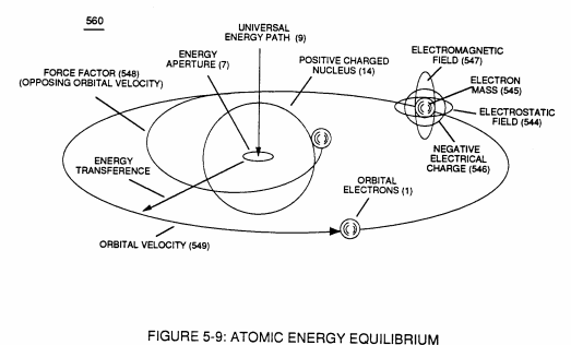](https://stanslegacy.com/uploads/images/gallery/2024-03/3m099klTZk3n4XXJ-image-1709344438672.png)... of which, this scenario does not exist nor takes place. In essence then, the in-flowing of **Universal Energy** (9) into, through, and beyond the **Energy Spectrum of the atom**, now, establishes the fact that the atom simply functions as an “**Energy Transporter**.”
**Universal Energy** is, then, the prime source of energy that basically fuels are physical universal ... It's the energy source that not only sustains and maintains our physical universe but is the energy source that continually creates and recreates (example, growing plants seasonally) our physical universe.
> “Particle Oscillation as an Energy Generator” by way of pulsating electrical stress via WFC technology of inventions demonstrates, quite aptly, on how the reformation of the water molecule without destroying the water molecule atoms can be utilized to tap into this endless supply of universal energy, see [**WFC memo 424** titled “**\* Atomic Energy Balance of Water**](https://stanslegacy.com/books/the-birth-of-new-technology/chapter/wfc-424-atomic-energy-balance-of-water "WFC 424 - Atomic Energy Balance of Water")” as in reference to **WFC Technical Supplemental Report (TSR)** titled “A Perspective View on Water as Fuel Endless Source of Clean Energy.” # WFC Atomic Degaussing Process The orbital gyroscopic architecture (6a xxx 6n) of WFC Figure (5-1) / WFC Figure (10-6) as to Figure (5-10) existing within the nucleus of the atom functions as a “**Energy Regulator**” (*orbital velocity attenuator*) since the overall **electrical bonding force** (zz’) of the **orbital sub-****particle**(s) (542) of Figure (5-8) (*geometrically grouped together*) is directly linked to the **Energy Aperture** (7) by way of **electrical intensity** (qq’) (*electrical attraction force that exists between* *Opposite charged mass entities*) which, in turns, is directly controlling a quantum influx of energy into the energy spectrum of the atom in order to maintain the orbital spin velocity of the electron(s) (549) of Figure (5-9) at a given energy level to promote stable state of equilibrium of the atom.| WFC Figure (5-1)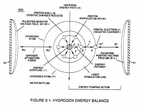 | WFC Figure (5-10) [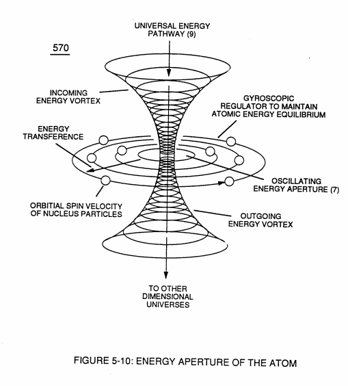](https://stanslegacy.com/uploads/images/gallery/2024-03/1hHSEjLQQsjc0DQh-image-1709345220720.png) |
… meaning that the orbital pathway(s) of the orbiting **sub-particle**(s) (542) (*geometrical configuration*) are moving in a circular motion about the axis of the **Energy Aperture** (7) at a constant spin/velocity and that the **sub-particles** (542) are being displaced uniformly ... and that the electrical intensity (qq’) between the orbiting **sub-particle**(s) (542) and the **Energy Aperture** (7) of the nucleus of the atom remains constant ... a condition by which the atom is not radioactive.
[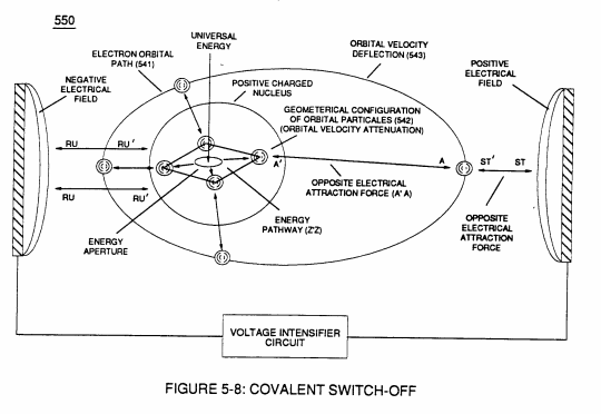](https://stanslegacy.com/uploads/images/gallery/2024-03/QgHLJEWBdtcSiwIF-image-1709348606364.png) # State of Unbalance The quiescent atom remains at stable state of equilibrium and does not become radioactive until the atom absorbs a given quantum-amount (*high-energy end of the electromagnetic energy spectrum*) of electromagnetic energy (gamma radiation) into the energy spectrum of the atom.Once absorbed, the atom reaches a “**State of Unbalance**” when the orbital sub-particles pathway (s) (542) of Figure (5-8) are deflected (moved) to a higher energy state which, in turns, induces a change in the orbital pathway (s) from an circular to an elliptical configuration since the orbiting sub-particles (542) are regrouped to from a different and distorted arrangement... being displaced unevenly ... thereby, setting up a condition by which the atom, now, becomes radioactive ... an emitter of electromagnetic energy.
The degree by which the atom becomes more radioactive is simply determined by either the atom absorbing additional incoming gamma radiation (very energetic X-rays) and/or accepting alpha (consist of two protons and two neutrons bound together), beta particle (nothing more than an electron (s), and/or neutron particles from another radioactive substance (s).In each and all unstable condition (s), the elliptical pathway of the orbiting sub-particles becomes even more exaggerated (increasing the wobbling effect) .. and, proportionally causing the atom to become even more unbalanced (becoming more radioactive).
This unbalance state of condition(s), now, causes the **Energy Aperture** (7) to start to oscillate (*be elongated repeatedly*) in direct relationship to the elliptical pathway of the **sub-particles** (542). As the orbiting sub-particle (542) approaches the apogee node of the elliptical movement, the **Energy Aperture** (7) is elongate to a larger opening ... thereby, allowing more energy to go into and to be absorbed and pass through the energy spectrum of the atom. When the perigee node of the elliptical movement is alternately reached, the **Energy Aperture** (7) opening is reduced in size and thereby shuts-off the flow of inputted energy going into the energy spectrum of the atom. This “**Oscillatory Action**” of switching on and off the energy flow going into the atom, now, causes the unstable atom to become radioactive (emitting radiation) since the **Oscillatory Action** energy-primes the atom beyond normal energy-levels. The unstable (unbalanced) atom continues to be an emitter of electromagnetic energy (*radiation*) until the atom is returned to a stable state of equilibrium by way of atomic decay.To achieve and bring about atomic decay in an instant of time, one needs only to expose the unstable atom to a high pulsating “**Electrical stress**” across the individual radioactive atom by way of opposite voltage potential, as so illustrated in (550) of Figure (5-8) by the use of **WFC Voltage Intensifier Circuit** as so defined in [WFC memo 426](https://stanslegacy.com/books/the-birth-of-new-technology/chapter/wfc-426-vic-matrix-circuit "WFC 426 - VIC Matrix Circuit") titled “**VIC Matrix Circuit**.”
This applied pulsating electrical stress actually physically “**Rings**” the unstable atom to perform the **Atomic Degaussing Process** instantly rather than relying on normal half-life cycling (typically, thousands of years) since the applied “Electrical Stress” effects (attenuates) the electric field strength (qq’) (electrical attenuation Aqq’) of the atom... being that, the atom is composed of electrical charged particles of different electrical intensities, as so illustrated in [**WFC Memo 424**](https://stanslegacy.com/books/the-birth-of-new-technology/chapter/wfc-424-atomic-energy-balance-of-water "WFC 424 - Atomic Energy Balance of Water") titled “**Atomic Energy Balance of Watér**.” Within the Atomic structure, the Proton exhibits a **Positive electrical charge** (B+), electrons emanates an **negative electrical charge** (B-), and neutrons which is/are made up of a **positive charged Proton** (B+) electrically bonded together (*opposite electrical attraction force qq’*) with an **negative charge electron** (B-). These electrical charged particles that make up the atom structure are interrelated and held together by an **Electrical Bonding Force** (electrical attraction force (qq’) that exists between each opposite electrical charged mass entities) since each individual and separate sub-atomic particle mass entity exhibits one of the two **opposite electrical charged fields** (B+) or (B-). # Wobbling Effect Electrical attenuation of the unstable (radioactive) atom **Electrical Bonding Force**(s) (*Electrovalent Bonding Force*) (qqa’ xxx qqb’) by subjecting and exposing the unstable atom to “**Electrical Stress**” of opposite voltage polarity simply causes the atom to return to stable state of equilibrium (no longer radioactive) by causing the unstable atom to give up any unwanted mass entity (s) such as an extra neutron(s), proton(s), and/or electron(s) which is directly contributing to the **Wobbling Effect** (unbalance condition of the atom). [](https://stanslegacy.com/uploads/images/gallery/2024-03/UATXLHDLefGrFI0N-image-1709348979225.png) **Electrical attenuation** (Aqq) of the **Electrical Bonding Force** (qq’) of the unstable atom occurs when opposite electrical attraction forces (RU-RU’ / ST’-ST) are set up between the electrical charged sub-particles of the atom and the recurring pulsating **electrical voltage fields** (E15/E16) of opposite electrical polarity of potential (B+/B-), as so illustrated in (1020) of Figure (11-1) titled “**Neutron Electrical Polarization Process**” as to Figure (10-1) titled “**Voltage Intensifier Circuit**”. When applied, the opposite voltage fields (E15/E16) overcomes the electrovalent bonding force (qq’) that exists between the two unlike electrical charged subatomic particles forming the neutron ... whereby, the **positive charged proton** (B+) is deflected toward stationary **negative voltage field** (B-) (B15) and, simultaneously, the **negative charged electron** (B-) is deflected in opposite direction toward the stationary **positive voltage field** (E16) since unlike charges attract (RU-RU’ / ST’-ST) under the law of physics … thereby, overcoming electrovalent bonding force (qq’). Once separated, the newly liberated proton and electron (*neutron no longer exists*) can be immediately captured by the unstable atom to cause the atom to transmute (*transform*) into another element having a different mass number.This “**Transformation of the Elements**” by way of electrical stress (hereinafter called **The Atomic Degaussing Process**) continues until the atom reaches a state whereby the newly formed stable atom has the same number of protons as to electrons and the number of neutrons remaining are such as to eliminate the “isotopes” condition of the the once unstable atom... **eliminating the Wobbling Effect** ... thereby, causing the atom to become non-radioactive.
The surplus electromagnetic energy (gamma ray absorption), if any, is simply absorbed into the energy spectrum of the atom when the atom transmutes into another element (s) during the **Neutron Electrical Polarization Process**, as so illustrated in (1020) of Figure (11-1). [](https://stanslegacy.com/uploads/images/gallery/2024-03/MNDSUewyToFHmPc9-image-1709348886294-08-02.png) Wherein, the newly liberated protons and neutrons from the de-materializing alpha Particles, further, contributes to the **Atomic Degaussing Process**, when exposed to the same pulsating “**Electrical Stress**,” as so illustrated in (1030) of Figure (11-2) titled “**Alpha Electrical Polarization Process**.” The **WFC Atomic Degaussing Process** can be used to alter the state of any unstable atom (s) that has become radioactive since each atom has the same electrical charged particle mass entities, just different in atomic numbers. Remember, all substances are composed of atom structures grouped in different molecular forms. [](https://stanslegacy.com/uploads/images/gallery/2024-03/UJvUr3Q7ln5cUPcy-image-1709348924998-08-40.png)To ionize (*vaporize*) the nuclear spent fuel rods to allow the **Atomic Degaussing Process** to take place, simply expose the material of the nuclear spent fuel rods to a hydrogen/oxygen flame by the use of **WFC Technology of Inventions** that economically uses Water as Fuel ®.
# WFC 430-2 Illustrations| [](https://stanslegacy.com/uploads/images/gallery/2024-03/cKX2MznNyLwbmVWP-image-1709348704973.jpg) | [](https://stanslegacy.com/uploads/images/gallery/2024-03/2tRCZSmVWmj639YW-image-1709348730498.jpg) |
| [](https://stanslegacy.com/uploads/images/gallery/2024-03/rwg25OpNyMfDjvVO-image-1709348821506.JPG) | [](https://stanslegacy.com/uploads/images/gallery/2024-03/nJKgZUacTqQWbu77-image-1709348714592.jpg) |
| [](https://stanslegacy.com/uploads/images/gallery/2024-03/jmrzYOh3N7ekC0Yd-image-1709348844511.jpg) | [](https://stanslegacy.com/uploads/images/gallery/2024-03/6kczmcKC9LqcjgyO-image-1709348752080.jpg) |
| [](https://stanslegacy.com/uploads/images/gallery/2024-03/Ai9Pp6LYsvuv2pOP-image-1709348764519.jpg) | [](https://stanslegacy.com/uploads/images/gallery/2024-03/la2m8aFIeC2c5xva-image-1709348778864.jpg) |
| [](https://stanslegacy.com/uploads/images/gallery/2024-03/MNDSUewyToFHmPc9-image-1709348886294-08-02.png) | [](https://stanslegacy.com/uploads/images/gallery/2024-03/UJvUr3Q7ln5cUPcy-image-1709348924998-08-40.png) |
**Hydrogen Storage** is "Not" required since hydrogen gas is being produced on demand.
[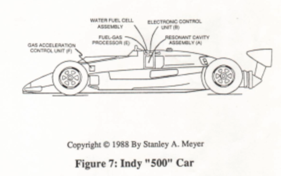](https://stanslegacy.com/uploads/images/gallery/2024-03/Hd0xmXHC2MgFrD3O-image-1711386518282-08-35.png) Original Content Image 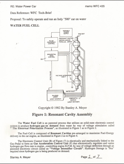 # Fuel Gas Processor An patented **Electron Extraction Circuit** is incorporated into the **Fuel-Cell** circuitry to produce **Electrical-Energy** directly from water which, in turn, aids the **Voltage Stimulation Process** (**Electrical Polarization Process**) through an **Regenerative Energy Feedback Network System**. Activating **Safety Control Circuit** (D) of Figure (6) not only de-energizes the entire **Fuel-Cell** circuitry during emergency shut-down conditions but also “Vents” the **Fuel-Cell** gases as well. The vent or “**Pop-Off**” valve is also used to bleed-off unwanted gas pressure.High Impact plastic forms the **Fuel-Cell** housing to prevent spark-ignition of the **Fuel-Cell** gases during **Fuel-Cell** “**Power On-Stage**”.
--- ##### [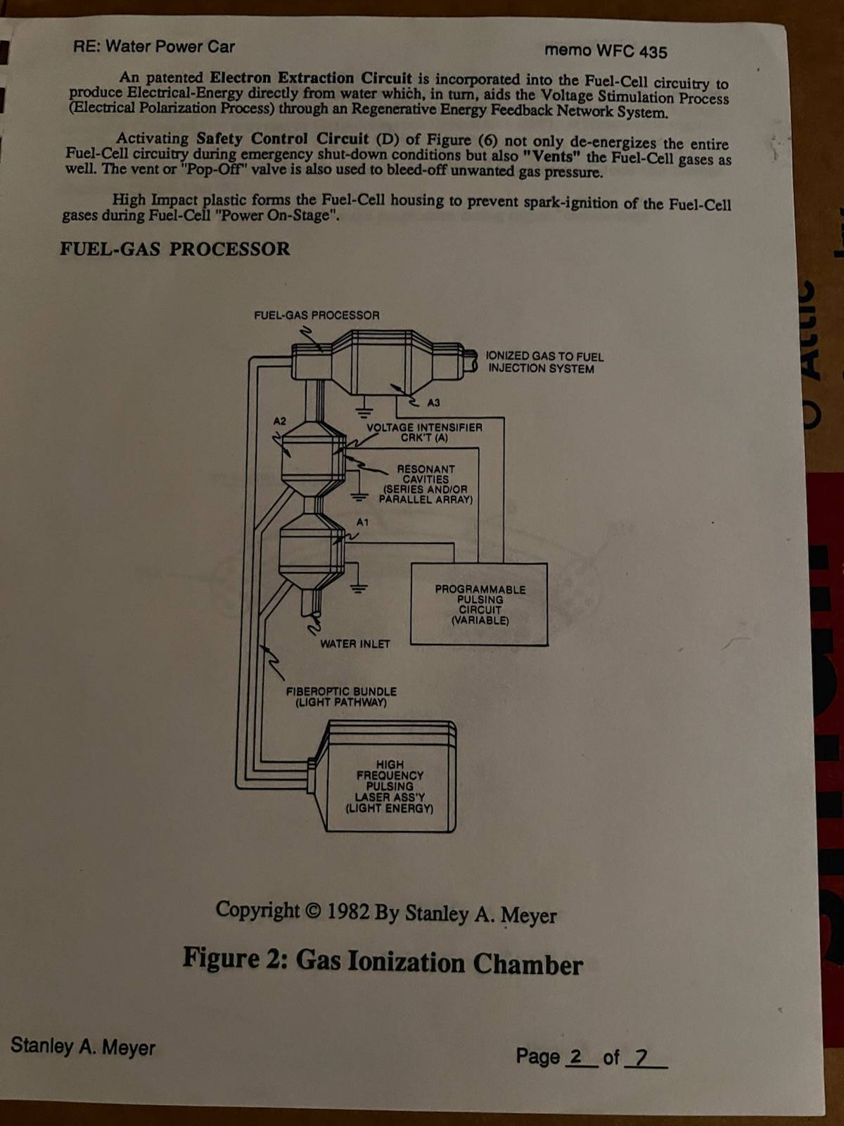](https://stanslegacy.com/uploads/images/gallery/2026-01/QkVYgHmxK8z8eJQH-image-1767296048417.png)*(Diagram labels as shown)* - **FUEL-GAS PROCESSOR** - **IONIZED GAS TO FUEL INJECTION SYSTEM** - **VOLTAGE INTENSIFIER CRKT (A)** - **RESONANT CAVITIES (SERIES AND/OR PARALLEL ARRAY)** - **PROGRAMMABLE PULSING CIRCUIT (VARIABLE)** - **WATER INLET** - **FIBEROPTIC BUNDLE (LIGHT PATHWAY)** - **HIGH FREQUENCY PULSING LASER ASS’Y (LIGHT ENERGY)** --- Copyright © 1982 by Stanley A. Meyer **Figure 2: Gas Ionization Chamber** # Fuel-Gases / Quenching Tube The liberated and traveling **Fuel-Gases** enters into ans passed through a patented **Fuel-Gas Processor (E)** that performs and functions as a **Gas Ionization Chamber** when another Voltage Intensifier Circuit (A3) is activated by Gas Acceleration Control Unit (B/F), as illustrated in Figure 2 as to Figure 7| Figure 2 | Figure 7 [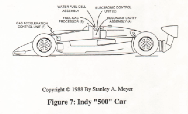](https://stanslegacy.com/uploads/images/gallery/2024-03/g89dHgK61mVqLq6c-image-1711427969697-39-26.png) |
The hydrogen gas-mixture remains constant regardless of the gas flow-rate since water acts and performs as a Gas-Mixing Regulator.
| Figure 4 [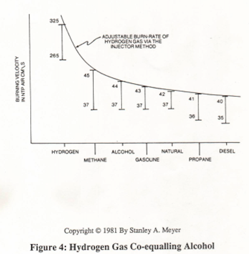](https://stanslegacy.com/uploads/images/gallery/2024-03/ReP7S3MbPuRQ7AA5-image-1711427624998-33-42.png) | Figure 5 [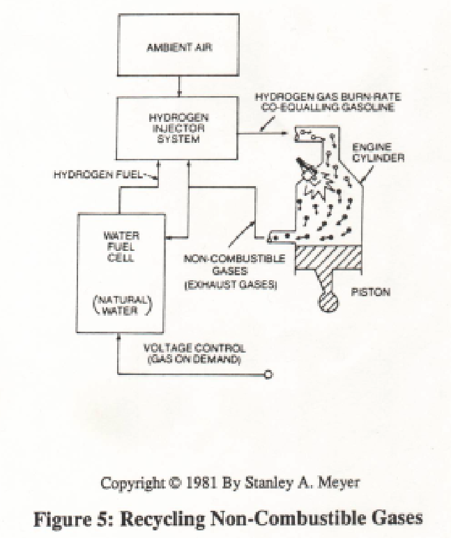](https://stanslegacy.com/uploads/images/gallery/2024-03/OxWmJ0JJo98klZ8H-image-1711427675508-34-33.png) |
The engine provides the non-combustible gases on demand since **Ambient Air** is used firing the **Gas Combustion Process**.
[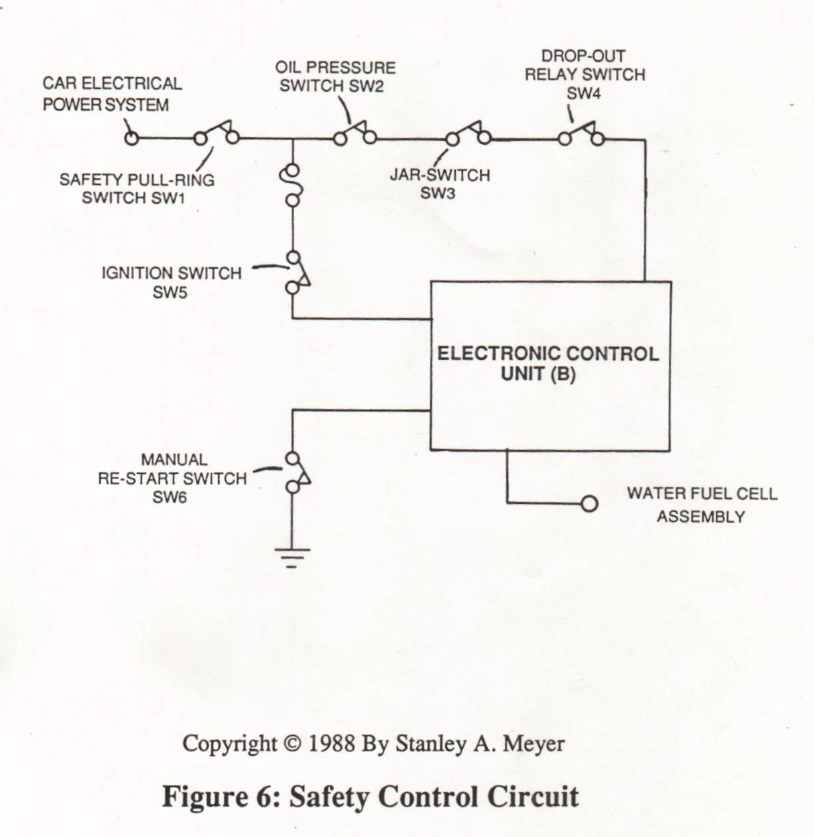](https://stanslegacy.com/uploads/images/gallery/2024-03/QmsxrcodIkfPZNKh-image-1711428480735-47-58.png) # Water Powered Car In case of engine failure, **Safety Control Circuit** (H) of Figure (6) is automatically activated to "switch-off" power loading to **Electronic Control Unit** (B) ...electrically de-energizing the **Fuel-Cell** ...stopping gas-flow to engine. **Oil Pressure Switch (SW2)** is activated when engine oil pressure "Drops" to a predetermined level. **Jar-switch (SW3)** is activated when a car crash occurs; whereas "Drop-out" **Relay-Switch** (SW4) is activated when **Electronic Control Unit** (B) senses a **Fuel-Cell** malfunction. [](https://stanslegacy.com/uploads/images/gallery/2024-03/g89dHgK61mVqLq6c-image-1711427969697-39-26.png)Retrofitting **The Water Fuel Cell** to an Indy "500" Car does "Not" compromise the **Safety Integrity** of the car but rather promotes **Driver Safety** since water is a non-burnable **Fuel-Liquid**.
# WFC MEMO - 423-CX # Cover Page [](https://stanslegacy.com/uploads/images/gallery/2024-10/EIxJX3hqFnlXs6da-image-1729211294324.png)