# Water Fuel Injector (Taper Resonant Cavity Chamber)
#### Taper Resonant Cavity Chamber
To set up, trigger, and perform **Hydrogen Fracturing Process** (390) of Figure (3-42) (see [WFC Memo 422 DA](https://stanslegacy.com/books/the-birth-of-new-technology/chapter/wfc-422da-wfc-hydrogen-gas-management-system "WFC 422DA - WFC Hydrogen Gas Management System")) **gas ignition stage** (100) of Figure (6) ...
releasing thermal explosive energy (gtnt) via **flame projection** (16) of Figure (3B) as to Figure (14), **Water Fuel Injection System** (10) of Figure (1) as to (170) of Figure (13) incorporates and uses **Taper Resonant Cavity Chamber** (180) of Figure (14) to enhance operational parameters of **Hydrogen Fracturing Process** (100) of Figure (6) being stimulated to activation by **opposite electrical voltage fields** (49/51) of Figure (3B) as to (180) of Figure (14).
| **flame projection** (16) of Figure (3B)
[](https://stanslegacy.com/uploads/images/gallery/2024-03/lEKSdZZG5WiUvmUW-image-1711235079510-04-35.png)
| **Water Fuel Injection System** (10) of Figure (1)
[](https://stanslegacy.com/uploads/images/gallery/2024-03/5G6eSwP2K8xbGh7N-image-1711239688578-21-26.png)
| (170) of Figure (13)[](https://stanslegacy.com/uploads/images/gallery/2024-03/OUpVseXIiARHRB16-image-1711239747353-22-24.png) |
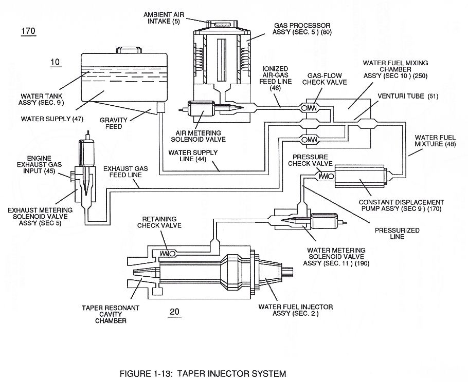
[](https://stanslegacy.com/uploads/images/gallery/2024-03/mMcNeHkTnD6lnRzb-image-1711239975992-26-13.png)In like manner, **water supply** (10) of Figure (170), **non-combustible gases** (45) (*Engine Exhaust gases*), and **ambient air ionized gases** (46) (*air gases having missing electrons*) are uniformly intermixed when moving into, passing through and beyond **fluid mixing chamber** (250) of Figure (13) by way of **venturi tube-cavity** (51)...
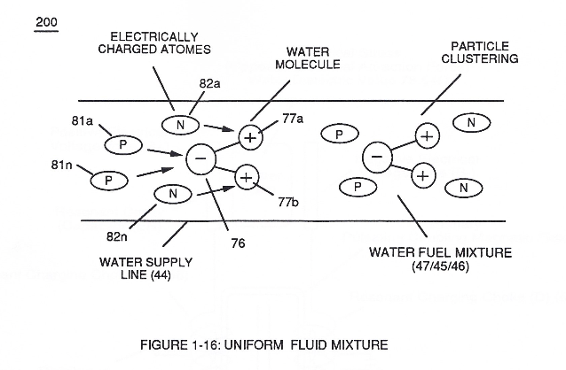
allowing water fuel mixture (47/45/46) (48) to be particle aligned by opposite electrostatically charged atoms
...positive charged gas particles (81a xxx 81n) being directed to and attached to negative charged oxygen atom (76) of water molecule (47);
while, during the same interim period of time, **negative charged gas particles** (82a xxx 82n) being directed onward to and affix themselves to **positive charged hydrogen atoms** (77a / 77b), as illustrated in (200) of Figure (16).
[](https://stanslegacy.com/uploads/images/gallery/2024-03/5phF31y6vSDzGYIk-image-1711240076581-27-54.png)
The resultant water fuel-mixture (48) is, now, pressurized up to and beyond 125 lbs of fluid-pressure by **Fluid Displacement Pump** (170) of Figure (13), as before, to cause and form water fuel-droplets (48a xxx 48n) when water fuel (48) enters into, passes through and beyond spray ports (41a xxx 41n) forming **Quenching Disc Structure** (190) of Figure (15).
| **Fluid Displacement Pump** (170) of Figure (13)
[](https://stanslegacy.com/uploads/images/gallery/2024-03/Uc94Wno727HBNfNf-image-1711241901925-58-18.png)
| Quenching Disc Structure (190) of Figure (15)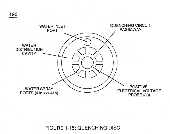 |
The injected **water fuel-droplets** (48a xxx 48n), now, surrounds outer surface area of exposed **positive probe** (33) while entering into **Taper Resonant Cavity** (180), as illustrated in (70) of Figure (3B) as to Figure (14).
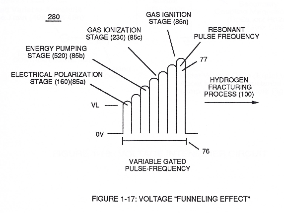
Once water fuel-droplets (xxx 48n) fully occupies open space cavity (**Resonant Cavity Zone**) (35) and then exposed to applied pulsating opposite electrical voltage fields (49/51) of voltage wave form (280) of Figure (17), the electrically stimulated water fuel droplets (48a xxx 48n) are subjected to release thermal explosive energy (gtnt) (16) undergoing **Electrical-Resonant** in a sequential manner:
[](https://stanslegacy.com/uploads/images/gallery/2024-03/pHJJMAHMYDulX5HH-image-1711242198362-03-15.png)
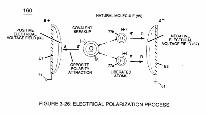
By **first**, separating water molecule (47) into its component gases (oxygen 76 / hydrogen 77a - 77b) by way of the Electrical Polarization Process (160) of Figure (25) ([WFC Memo 422 DA](https://stanslegacy.com/books/the-birth-of-new-technology/chapter/wfc-422da-wfc-hydrogen-gas-management-system "WFC 422DA - WFC Hydrogen Gas Management System"));
[](https://stanslegacy.com/uploads/images/gallery/2024-03/LoJA7Rs0RRNkGufD-image-1711240326284.png)
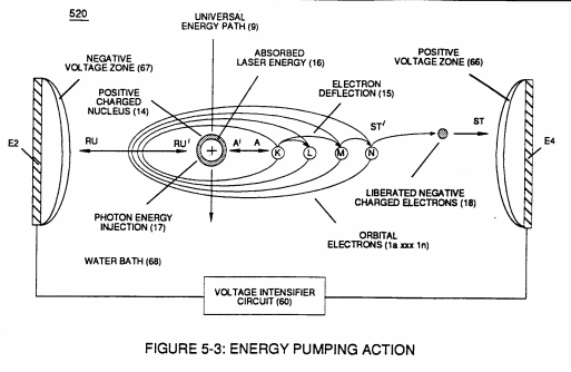
**secondly**, by electrically attenuating the electrical-forces of the newly formed and liberated combustible gases (76, 77a - 77b) via Energy-Priming Process (520) (see [WFC Memo 424](https://stanslegacy.com/books/the-birth-of-new-technology/chapter/wfc-424-atomic-energy-balance-of-water "WFC 424 - Atomic Energy Balance of Water") titled "Atomic Energy Balance of Water);
[](https://stanslegacy.com/uploads/images/gallery/2024-03/gX9NnG55mQj0YygS-image-1711240273862.png)
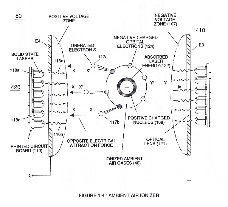
**thirdly**, by ionizing the released combustible gases by way of **Electron Ejection Process** (230) of Figure (29) ([WFC Memo 422 DA](https://stanslegacy.com/books/the-birth-of-new-technology/chapter/wfc-422da-wfc-hydrogen-gas-management-system "WFC 422DA - WFC Hydrogen Gas Management System")), as further illustrated in (80) of Figure (4);
| **Electron Ejection Process** (230) of Figure (29)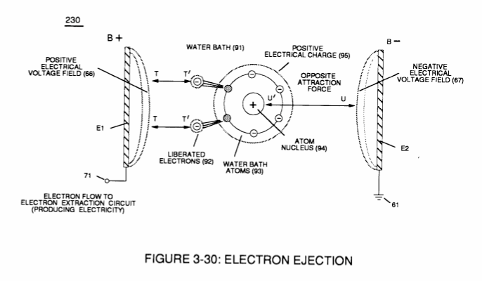
| (80) of Figure (4)
[](https://stanslegacy.com/uploads/images/gallery/2024-03/sxDuDQrTfViKX2st-image-1711240439701-33-56.png)
|
[](https://stanslegacy.com/uploads/images/gallery/2024-03/pHJJMAHMYDulX5HH-image-1711242198362-03-15.png)and **finally**, spark-ignite the highly destabilized combustible gases (laser primed combustible gases having missing electrons) by electrostatic discharge (kinetic energy agitation), as further exemplified in (280) of Figure (17);
all sequential gas priming functions occurring progressively in an instant of time.
Subsequent and repetitive formation of applied **gated electrical voltage pulse-train** (210a xxx 210n) of Figure (17) to continued in-flow of **water fuel droplets** (48a xxx 48n) not only sustains and maintains **Hydrogen Fracturing Process** (100) of Figure (6) but, also, regulates **Thermal Explosive Energy** release (16a x 16n) of Figure (14) by attenuating applied voltage amplitude (xxx VL xxx), as graphically shown in Figure (20F) ([WFC Memo 420](https://stanslegacy.com/books/the-birth-of-new-technology/chapter/wfc-420-hydrogen-fracturing-process "WFC 420 - Hydrogen Fracturing Process")).
| **Hydrogen Fracturing Process** (100) of Figure (6)
[](https://stanslegacy.com/uploads/images/gallery/2024-03/JqeitiAp4qURSnQb-image-1711239500177-18-17.png)
| **Thermal Explosive Energy** release (16a xxx 16n) of Figure (14)
[](https://stanslegacy.com/uploads/images/gallery/2024-03/lEKSdZZG5WiUvmUW-image-1711235079510-04-35.png)
|
This further increase in voltage amplitude (xxxx VL) simply exerts a greater magnitude of opposite **Electrical-Stress** (SS'-RR') of Figure (25) (TT' - UU') of Figure (29) ([WFC Memo 422 DA](https://stanslegacy.com/books/the-birth-of-new-technology/chapter/wfc-422da-wfc-hydrogen-gas-management-system "WFC 422DA - WFC Hydrogen Gas Management System")) across combustible gas atoms (76, 77a - 77b)
which, in turns, ejects a greater number of electrons while preventing the formation of the water molecule (390) of Figure (41) ([WFC Memo 422 DA](https://stanslegacy.com/books/the-birth-of-new-technology/chapter/wfc-422da-wfc-hydrogen-gas-management-system "WFC 422DA - WFC Hydrogen Gas Management System")) during thermal gas-ignition (180) of Figure (14).
Voltage Intensifier Circuit (220) of Figure (18) allows Electrical-Stress variation (SS' = RR' / TT' = UU') since **voltage Intensifier Circuit** (220) inhibits electron-flow (amp restriction) into voltage triggering process (210) of Figure (17) as to (100) of Figure (6).
[](https://stanslegacy.com/uploads/images/gallery/2024-03/UbQQXtm822UJY1my-image-1711238945929-09-03.png)
| voltage triggering process (210) of Figure (17)
[](https://stanslegacy.com/uploads/images/gallery/2024-03/pHJJMAHMYDulX5HH-image-1711242198362-03-15.png)
| (100) of Figure (6) |
Electron restriction while varying voltage intensity (Va = Vn) is accomplished by performing several functions simultaneously:
Incoming **pulse-train** (210a xxx 210n) is adjusted to "tune-in" to the Dielectric Properties of Water (47) which allows Resonant Action (see [WFC Memo 424](https://stanslegacy.com/books/the-birth-of-new-technology/chapter/wfc-424-atomic-energy-balance-of-water "WFC 424 - Atomic Energy Balance of Water"), once again) to occur since the Dielectric property of water (*78.54 value*) becomes a integral part of **Electronic Circuit** (110) of Figure (7) as to (220) of Figure (18)
| **Electronic Circuit** (110) of Figure (7)
[](https://stanslegacy.com/uploads/images/gallery/2024-03/aEKWjdeQv4j5D9sz-image-1711246045987-07-24.png)
| (220) of Figure (18)
[](https://stanslegacy.com/uploads/images/gallery/2024-03/UbQQXtm822UJY1my-image-1711238945929-09-03.png)
|
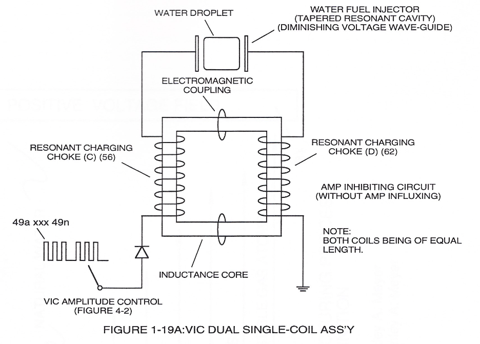
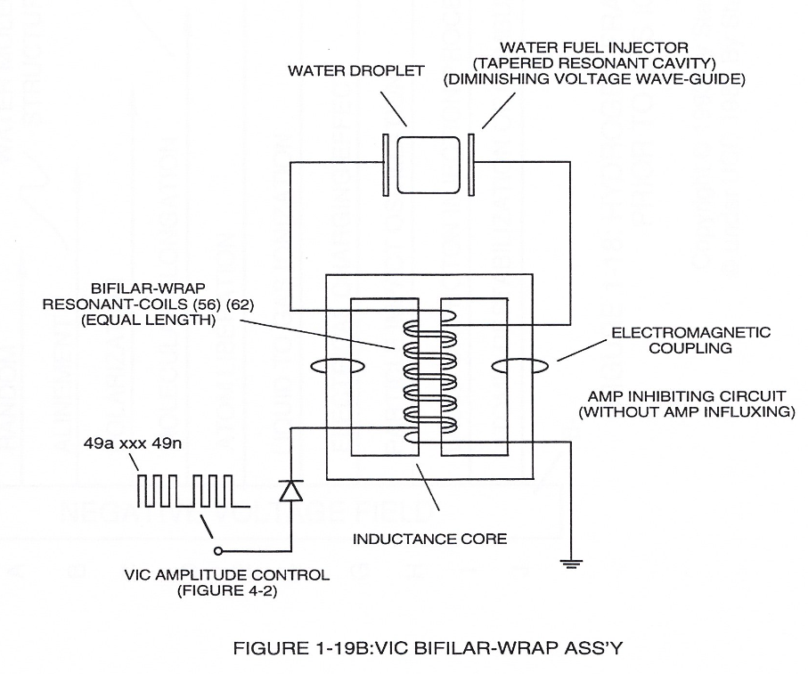
... forming a capacitor (E7 / E8) in series with Resonant Charging Chokes (56/57) placed on opposite sides of Resonant Cavity Zone (35) as to Figure (7) and (8) . . . forming a Resonant Pulsing Circuit (110) of Figure (7) with step-up **Pulsing Transformer** (33/36), as shown in (220) of Figure (18).
Adjusting Pulse-train (210a xxx 210n) in such a way as to allow pulse off-time (T2) to be synchronized with collapsing and re-formation of electromagnetic field coupling across pulsing transformer (52/53) to produce unipolar pulse frequency (T1a xxx T1n), as illustrated in (220) of Figure (18) as to Figure (17).
Pulse on-time (T1) having a predetermined **constant voltage level** (xxx VL xxx) is adjusted to maximize transference of electromagnetic energy to **Secondary Coil** (53) during pulsing operations.
The resultant and newly formed **gated** **Resonant Pulse-train** (T1 + T2a xxx T1 + T2n) (58) voltage amplitude (Vo xxx Vn) is, now, attenuated by **Sequential Voltage Amplitude Control Circuit** (59) once step up **Secondary Coil** (53) produces a higher voltage level (xxxVL) above incoming **pulse-train** (210) since **Secondary Coil** (53) has a greater number of turns of wire.
| [](https://stanslegacy.com/uploads/images/gallery/2024-03/ENk0b7D7uh9mDVXX-image-1711236926123-35-23.png) | [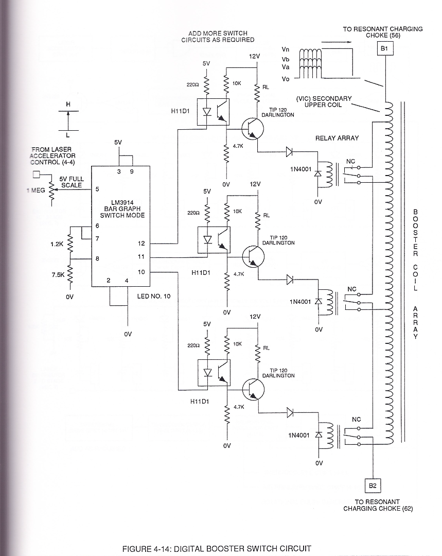](https://stanslegacy.com/uploads/images/gallery/2024-03/2AJ8bEqLZFOJQtAM-image-1711238092887-54-49.png)
|
**Sequential Switch Circuit** (59) simply switches in and out **Booster Pickup Coils** (61a xxx 61n) in series electrical hookup with **Secondary Coil** (53) output to elevate voltage intensity across Resonant Charging Chokes (56/57).
Forming Resonant Charging Chokes (56/57) by using Stainless Steel Electro-Inductance wire-material (430F / T304 or equivalent) which, when electrically pulsed transmits voltage intensity while restricting amp flow during Resonant Pulsing operations. Together, the resistive valve of Stainless Steel wire-coil (56/57) and its inductance generated electromagnetic field (62) of Figure (19) opposes the movement of electrons since the dielectric valve of wire-coils (56/57) inhibits electron exchange while the generated inductance field (62) locks onto the electromagnetic field of the electrons ...generated coil inductance field (62) being greater in electromagnetic... \[ends abruptly...\]
| [](https://stanslegacy.com/uploads/images/gallery/2024-03/ItHbfV0yw5rt3wzS-image-1711238896182-08-12.png)
| [](https://stanslegacy.com/uploads/images/gallery/2024-03/9fhLQE7R6ZHcUQyz-image-1711238904577-08-22.png) |
#### The Following Page 1-7 was not available
The "**Plus Factor**" is that induce **external** **electromagnetic field** (63/64) across **Resonant coil-Tap** (67) increases voltage intensity (*voltage potential*) still further rather than diminishes peak voltage potential due to resistive valve of the stainless steel wire.
In other words, the inductance and capacitance values of **stainless steel induction coil** (56/57) bypasses voltage drop across its resistive load (ohmic valve of wire).
This induced voltage phenomenon encourages and therefore prevents resonant **pulse frequency** (58) from being impaired or altered while being electrically transmitted to **Resonant Cavity** (180) of Figure (14) via electrical tabs (71) and (72) of Figure (14).
[](https://stanslegacy.com/uploads/images/gallery/2024-03/lEKSdZZG5WiUvmUW-image-1711235079510-04-35.png)