Voltage amplitude level VL of **Pulse-wave** (58) is predetermined (*20,000 V.D.C. typically)* to start and cause **Electrical Polarization Process** (160) at a relative rapid rate of gas production at segmental point (85a) when voltage point (VL xx Va) is reached.
As voltage intensity increases (VL x Va x Vb) onward segmental point (85b), **Energy Pumping Action** (520) of Figure (4-3) ([WFC Memo 424](https://stanslegacy.com/books/the-birth-of-new-technology/chapter/wfc-424-atomic-energy-balance-of-water "WFC 424 - Atomic Energy Balance of Water")) as to (280) of Figure (34) ([WFC Memo 422 DA](https://stanslegacy.com/books/the-birth-of-new-technology/chapter/wfc-422da-wfc-hydrogen-gas-management-system "WFC 422DA - WFC Hydrogen Gas Management System")) is activated to peak performance levels.| (520) of Figure (4-3) [](https://stanslegacy.com/uploads/images/gallery/2024-03/gQbpGVKKKqmEbEYT-image-1711236158134-22-35.png) | (280) of Figure (34) [](https://stanslegacy.com/uploads/images/gallery/2024-03/HYSxIlsAQa2ancBF-image-1711236265839-24-23.png) |
At segmental point (85c) voltage intensity (VL x Va x Vb x Vc) is increased sufficiently enough to propagate **Gas Ionization Process** (230) of Figure (3-30) ([WFC Memo 422 DA](https://stanslegacy.com/books/the-birth-of-new-technology/chapter/wfc-422da-wfc-hydrogen-gas-management-system "WFC 422DA - WFC Hydrogen Gas Management System")).
[](https://stanslegacy.com/uploads/images/gallery/2024-03/pe6afqhEDgTyKAXl-image-1711236372677-26-10.png) At termination point (85), voltage intensity (VL x Va x Vb x Vc x Vn) is, now, increased to the point to cause **Gas Ignition** as **Combustible Gas Atoms** (76, 77a - 77b) which are, then, expelled from **Gas Nozzle Port** (87) of Figure (14) under dynamic pressure to allow **thermal gas expansion** (16) ... releasing thermal explosive energy (gtnt) beyond and away from **Resonant Cavity Chamber** (180), as illustrated in Figure (14). [](https://stanslegacy.com/uploads/images/gallery/2024-03/lEKSdZZG5WiUvmUW-image-1711235079510-04-35.png) To prevent pre-ignition of gases traveling toward **Exit-Port** (87), **Resonant Cavity** (35) open space (open resonant cavity) parallel dimension between positive voltage surface (82) and negative voltage surface (83) is small enough (typically .010 or so) to function as a **Quenching Circuit**, as illustrated in Figure (24SD) (missing image) ([WFC Memo 420](https://stanslegacy.com/books/the-birth-of-new-technology/chapter/wfc-420-hydrogen-fracturing-process "WFC 420 - Hydrogen Fracturing Process")). To increase energy levels (16a xxx 16L = 16n) of **Hydrogen Fracturing Process** (100) as to (390), even further, simply switch-on additional Booster Coils (61a x 61L - 61n) in sequential order to increase voltage intensity (VL ~ Vn ~ Vm) to higher magnitude of "**Electrical Force**" (Vma xxx Vmn) which is due to the inductance/capacitance values of each succeeding coil-structure (61a x 61n) forming **Booster coil-Assembly** (250), as illustrated in (240) of Figure (20).| [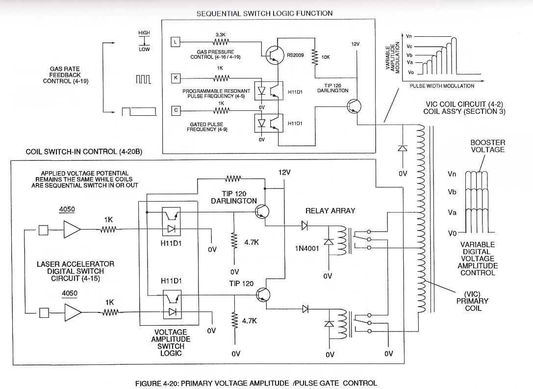](https://stanslegacy.com/uploads/images/gallery/2024-03/ENk0b7D7uh9mDVXX-image-1711236926123-35-23.png) | [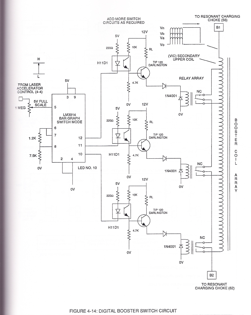](https://stanslegacy.com/uploads/images/gallery/2024-03/2AJ8bEqLZFOJQtAM-image-1711238092887-54-49.png) |
This resultant "**Shunting Effect**", now, allows voltage intensity (Vma = Vmn) to be placed across **Resonant Cavity Zone** (35) to not only compensate for water impurity that might alter the operational parameters of **Hydrogen Fracturing Process** (100) as to (390) but, also, provide "Instant" "Power-Boost" when needed.
| [](https://stanslegacy.com/uploads/images/gallery/2024-03/lEKSdZZG5WiUvmUW-image-1711235079510-04-35.png) | [](https://stanslegacy.com/uploads/images/gallery/2024-03/Qk1Jl0AL2SdmIEMn-image-1711237351260.png) |
The established "Power Boost" energy level (16a xxx 16n) is changeable, however, by, simply, electrically moving or displacing (back and forth movement) **Core-Slug** (73) to another stop-location (72)... adjusting energy-level (16a xxx) on demand.
In alternate form, **Core-Slug** (73) is replaced by a series of **Choke Coils** (77a xxx 77n) arranged in such a way as to increase voltage Intensity (Voltage Pulse Amplitude) (VL ~ Vn xxx) digitally by sequentially switching-on / switching -off Choke Coils (77a xxx 77n) to allow applied Voltage Intensity (VL ~ Vn xxx) to be placed across **Voltage Expander Coils** (78a xxx 78n) in direct relationship to electrically energized shunt-coil (76).
For example, as adjacent **Shunt-Coil** (76b) is switch-on while, simultaneously, **Choke Coil** (76a) is switch-off by **Electronic Switch Circuit** (79), Voltage Intensity (VL ~ Vn xxx) is increased due to inductance / capacitance of **Voltage Expander Coil** (78a) which is, now, added to **Electrical Circuit** (250) by electrical pathway (82a) since **electromagnetic coupling field** (76b) prevents electron flow to cause open circuit (82b)... (missing content) thereby establishing **Voltage Level Logic Function** (260) which is electronically transferable in sequential order (260a xxx 260n) by **Laser Acceleration Control Circuit** (4-4) of (220) of Figure (18). [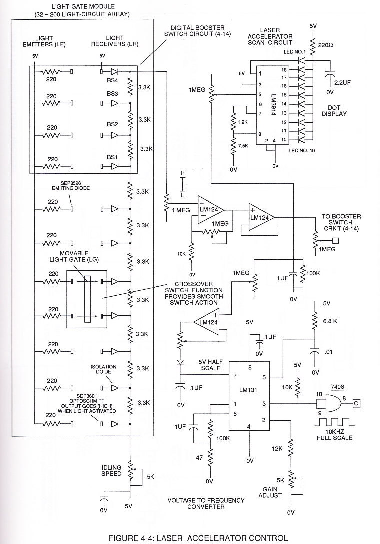](https://stanslegacy.com/uploads/images/gallery/2024-03/Xfkuluj5Fro9DYEl-image-1711238220068-56-57.png) thereby, attenuating voltage amplitude (voltage intensity) beyond **Secondary Coil** (53) **voltage levels** (71), as illustrated in (220) of Figure (18).Attenuating variable voltage amplitude (72a xxx 72n) in conjunction with incoming **gated pulse-train** (210a xxx 210n), now, expands **gated pulse width** (76a xxx 76n) as voltage amplitudes (Vo xxx Vn) increases, forming step up voltage wave Form (77) of Figure (17).
[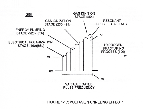](https://stanslegacy.com/uploads/images/gallery/2024-03/EmNtWjdZJcIuRmXm-image-1711238704911-05-02.png) This newly formed synchronized and repetitive dual expanding voltage wave form (77a xxx 77n) is further enhanced by "**Funneling Effect**" (260)... maximizing voltage dynamic across **Resonant Cavity** (35) always subjecting and exerting increase "**Electrical-Stress**" (SS'-RR' / TT'-UU') of opposite polarity across **Hydrogen Fracturing Process** (100 / 390) to the point of gas ignition. [](https://stanslegacy.com/uploads/images/gallery/2024-03/Qk1Jl0AL2SdmIEMn-image-1711237351260.png)