# 8-6 - VIC Voltage Sync-Pulse Circuit
**Voltage Sync-Pulse Gated Frequency** (583/602a xxx 583/602n) (603/604a xxx 603/604n) of Figure (8-1) as to (605/606a xxx 605/606n) (607/608a xxx 607/608n) (609/611a xxx 609/611n) of Figure (8-2)
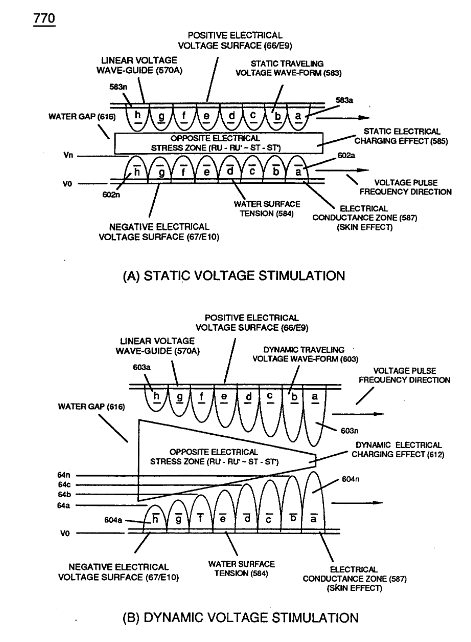
... all, forming **Voltage Pulse Burst Wave** (619) as to **Unipolar Pulse-Train** (780A), **Crossover Unipolar Pulse-Train** (780B), and **Clipped Unipolar Pulse Train** (780C) as to **Traveling Voltage Wave-Action** (770) of Figure (8-1) of opposite voltage polarity (+/-) of equal Voltage-Pulse Amplitudes (+Vpp/- Vpp) are zero reference to electrical ground state (0V) by placing **Amp Inhibitor Circuit** (860) (Amp Inhibiting Coil 617, Blocking Diode 618, and **Magnetic Induction Core** 619) between electrical ground (0V) and **Center Tap** of **Dual Bifilar Secondary Pickup Coils** (616A/B) of **VIC Matrix Circuit** (690) of Figure (7-8) as to **VIC Impedance Network Circuit** (620) of Figure (7-1) , as illustrated in (840) of Figure (8-10).
| [](https://stanslegacy.com/uploads/images/gallery/2023-12/DFvYW7H0AkLEYkFv-image-1702322742624.png)
| [](https://stanslegacy.com/uploads/images/gallery/2023-12/BA8yXHMaqNPV3DWk-image-1702322775259.png) |
By doing so, **Balance Phasing** of opposite voltage intensity (+Vpp / - Vpp) is accomplished without experiencing current influxing caused by differential variances where Negative Voltage Peak Potential (-Vpp) is less than Positive **Voltage Peak Potential (+Vpp)** or Vise Versa ... allowing Inductor **Resonant Choke Coils Electromagnetic Fields Intensity** (+Z2 / -Z3) to be, in turn, free of Electromagnetic variances of intensity (Z2 - Z3).
This non-voltage shift (**Balanced Phasing of opposite Voltage Potential**) helps prevents atom displacement during "**Snapping-Action**" by which "**Resonant Electrical Stress**" of opposite electrical polarity (RU/RU' - ST/ST') is applied equally across Water Molecule (s) (85) to propagate either **Static** (585) or **Dynamic** (612) **Electrical Charging Effect** (s) at elevated **Voltage Peak Potential** (s).
**[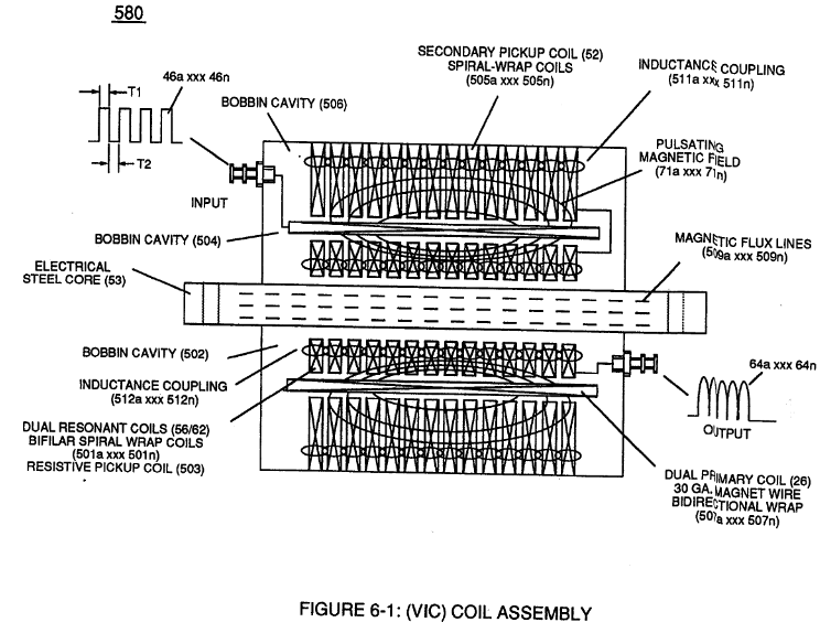](https://stanslegacy.com/uploads/images/gallery/2023-12/axyMmFebag8VQyKq-image-1702323131155.png)Amp Inhibiting Coil-Assembly** (617) is made up of magnetic inductance Stainless Steel 430FR wire material wrapped around a closed-loop Induction **Magnetic Core** (619) which is a separate coil-unit (860) apart from **VIC Coil Assembly** (580) of Figure (6-1).
Blocking Diode (618) functions as an "**Electrical Isolator**" that prevents electrical discharge of **Dual Secondary Coil** (616A / B) during applied Pulsing Operations (49a xxx 49n).
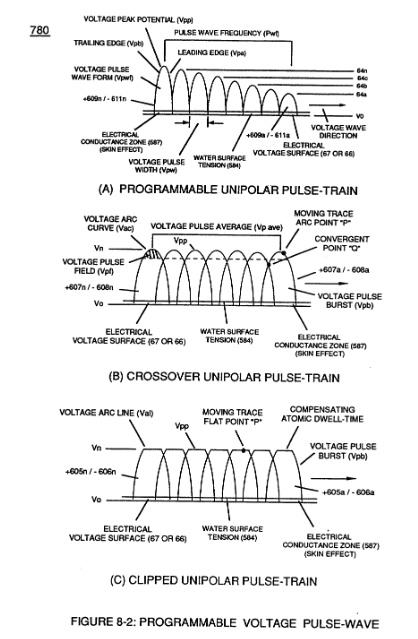
To ensure and maintain **Capacitance Charging Effect** (650) of Figure (7-4) across Water-Gap (Cp) of (7-8) during applied pulsing operations (49a xxx 49n), **Crossover Voltage Wave-Form** (780B) as to (780C) of Figure (8-2) is generally utilized by not allowing **Convergent Point "Q"** of Figure (780B) to reach **Electrical Ground Point** (0V) when each Unipolar Voltage Pulse (Vpp) is electrical energized in phase-distance relationship to cause the **trailing edge** (Vpb) of the **first Voltage-Pulse** (Vppl) to meet the **uprising leading** edge (Vpa) of the **second Voltage Pulse Wave** (Vpp2) at a distance above ground state (OV) determined by the Space-movement of the reforming **Voltage Peak Wave** (Vppa xxx Vppn) within Voltage Pulse Width (TI), as illustrated in **Rotary Crossover Voltage Sync-Pulse Circuit** (850) of Figure (8-11) where each VIC Pickup Coils (52A-52B -52C) are axially spaced 120· apart to cause **Convergent Point "Q"** to be located 1/3 the height of **Voltage Amplitude Peak Level** (Vpp), as an example.