| Figure (3-13) [](https://stanslegacy.com/uploads/images/gallery/2023-12/kaBCr5103gLcMT1t-image-1703194915396.png) | Figure (3-14) [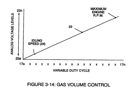](https://stanslegacy.com/uploads/images/gallery/2023-12/prG7V9Hd24ooi89W-image-1703195335274.png) |
The resultant and varied **voltage level** (22a xx) varies smoothly over a continuous range of **voltage valves** (22a xxx 22n) *rather than in discrete steps*, as illustrated in linear graph (23) of Figure (3-14).
In terms of functional-ability and purpose, **analog circuit** (40) of Figure (3-5) provides a variable (controlled) **voltage output** (23) in direct relationship to light gate (9) displacement which, in turns, sets up and controls **Resonant Action** (160) of Figure (3-23) that produces **Fuel Gases** on demand.
**[](https://stanslegacy.com/uploads/images/gallery/2023-12/prG7V9Hd24ooi89W-image-1703195335274.png)Analog circuit** (40) also calibrates both **engine idling speed** (22ax) and **maximum engine R.P.M.** (22a xxx 22n) by adjusting and maintaining a predetermined or given **low** (24) and **high** voltage levels respectively, as further illustrated in Figure (3-14).**Voltage valves** or **levels** (22a xxx 22n) simply controls the applied voltage potential across **Resonant Cavity Assembly** (120) of Figure (3-22) through **voltage amplitude control circuit** (50) of Figure (3-5) which is is electrically linked to **primary coil** (26) of Figure (3-22) of **Voltage Intensifier Circuit** (60) of Figure (3-5).
| Figure (3-22) [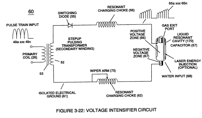](https://stanslegacy.com/uploads/images/gallery/2023-12/8ATrN3YcXfGXz0Kt-image-1703196300438.png) | Figure (3-5) [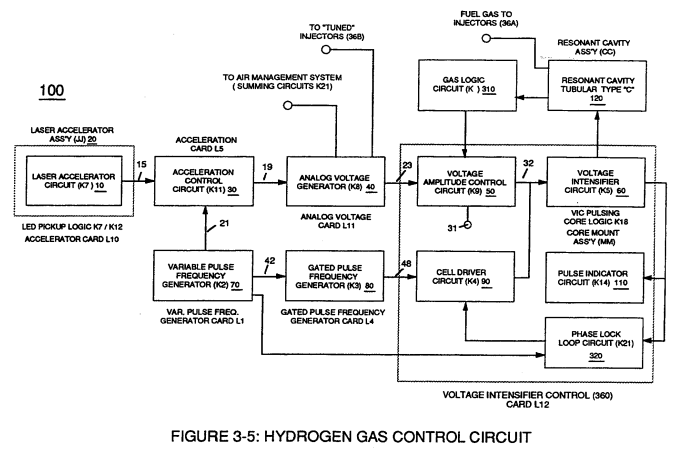](https://stanslegacy.com/uploads/images/gallery/2023-12/d5x6lw5jRAJT48i1-image-1703195613050.png) |