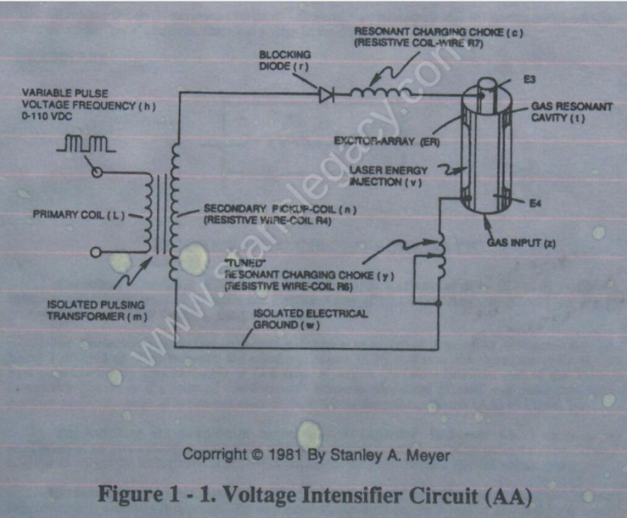
Voltage amplitude or voltage potential is increased when **secondary coil** (n) is wrapped with more turns of wire.
**Isolated electrical ground** (w) prevents electron flow from input circuit ground. ##### **BLOCKING DIODE** **Blocking Diode** (f) prevents electrical “shorting” to **secondary coil** (n) during pulse-off time since the diode “only” conducts electrical energy in the direction of the schematic arrow. --- **LC CIRCUIT** [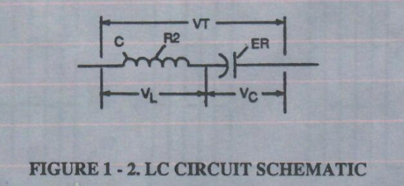](https://stanslegacy.com/uploads/images/gallery/2024-10/bz2ed0WefL8PK2ax-image-1729909194850.png)**Figure 1-2. LC Circuit Schematic****Resonant Charging Choke** (c) in series with **Excitor-array** (E3/E4) forms an **inductor-capacitor circuit** (LC) since the **Excitor-Array** (ER) of **Gas Resonant Cavity** (t) acts or performs as a capacitor during pulsing operations.
[](https://stanslegacy.com/uploads/images/gallery/2024-10/KHbfbIn48c46IpBu-image-1729909060083.png)The **Dielectric Properties** (*insulator to the flow of amps*) of **Argon Gas** (*dielectric constant being 1.000545 @ 23°C*) between the **electrical plates** (E3/E4) forms the **capacitor** (ER) of **Gas Resonant Cavity** (t). Gas Molecule or Gas atom of **Argon** (Ar) now becomes part of the Voltage Intensifier Circuit in the form of “resistance” between electrical ground and pulse-frequency positive-potential... helping to prevent electron flow within the **pulsing circuit** (AA) of Figure 1-1. The **Inductor** (c) takes on-or becomes a **Modulator Inductor** which steps up an oscillation of an given charging frequency when the effective capacitance of an pulse-forming network in order to charge the **voltage zones** (E3/E4) to an higher potential beyond applied voltage input. The **Inductance** (c) and **Capacitance** (ER of t) properties of the LC circuit is therefore “tuned” to resonate at a certain frequency.The Resonant frequency can be raised or lowered by changing the inductance and/or the capacitance values.
The established resonant frequency is, of course, independent of voltage amplitude, as illustrated in Figure 9BB.The value of the **Inductor** (c), the value of the **capacitor** (ER of t), and the pulse-frequency of the voltage being applied across the LC circuit determines the impedance of the LC circuit.