# Electrical Crossover Switching Circuit To reduce the number of **Voltage Intensifier VIC-Circuit** to the use of only one **VIC Coil Assembly** (1003) while encouraging the utilization of using a **Voltage Repelling Force** (W - W') and/or (TT'), **Electrical Crossover Circuit** (1060) of Figure (11-7) is, now, electrically placed between **VIC Coil Assembly** (1003) and both **Differential Voltage Wave-Guilds** (1030A / 1030B), as so illustrated in (1050) of Figure (11-7). [![image-1702703181359.06.17.png](https://stanslegacy.com/uploads/images/gallery/2023-12/scaled-1680-/drpReUoIHEUG3WYO-image-1702703181359-06-17.png)](https://stanslegacy.com/uploads/images/gallery/2023-12/drpReUoIHEUG3WYO-image-1702703181359-06-17.png)

The **Electrical Crossover Switching Circuit** (1060) singularly places either a **Positive Voltage Potential** (1014) across both **Voltage Zones** (E18/E14) and/or a **Negative Voltage Potential** across **Voltage Zones** (E17/E16) or vise versa.

In doing so, **Electrical Repelling Forces** (T-T') and (W-W'), now, exerts a "**Pushing Effect**" onto the already deflecting water molecules (1017/1018) since like electrical forces repel or push away from one another in a strictly physical manner. In terms of operational parameters, **Electrical Attraction Force** (S-S' / R-R') and **Repelling Forces** (T-T' / W-W') can be **applied simultaneously** or **applied in a time sequence of events** as **Electrical Crossover Switch Circuit** (1060) reverses the voltage polarity from one **Differential Voltage Wave-Guild** (1040B) to another and completely separate **Differential Voltage Wave-Guild** (1040A) of similar or like configuration
**Differential Voltage Wave-Guild** (1040A) [![image-1702703139186.05.36.png](https://stanslegacy.com/uploads/images/gallery/2023-12/scaled-1680-/rnbV8J5BtkPBnkGc-image-1702703139186-05-36.png)
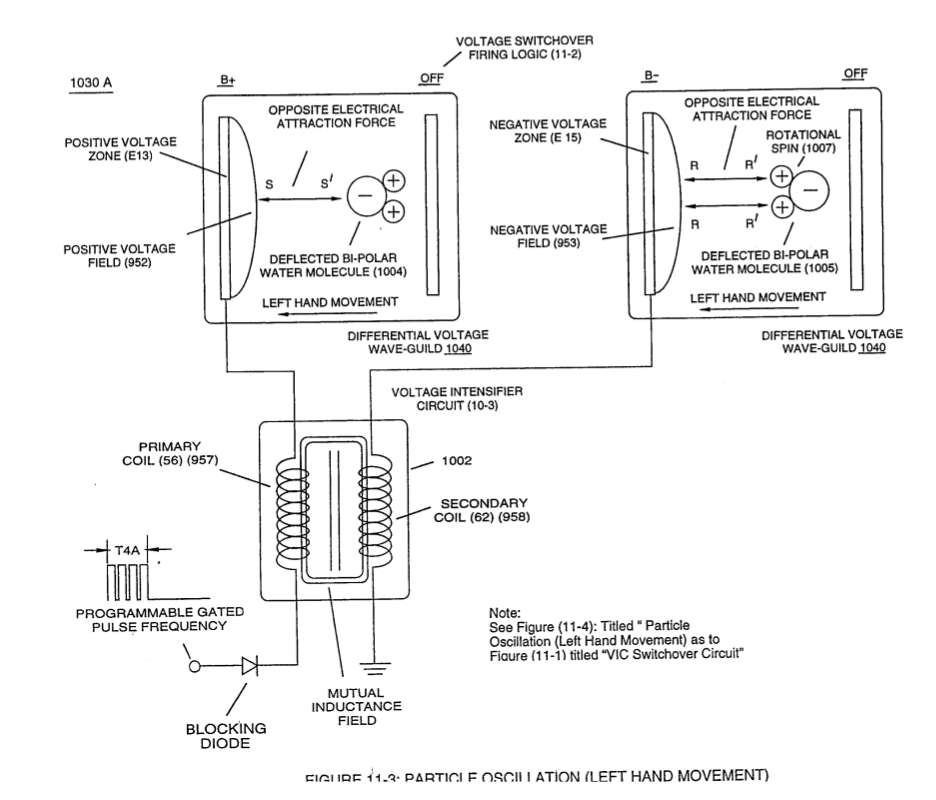
](https://stanslegacy.com/uploads/images/gallery/2023-12/rnbV8J5BtkPBnkGc-image-1702703139186-05-36.png) **Differential Voltage Wave-Guild** (1040B) [![image-1702703150322.05.48.png](https://stanslegacy.com/uploads/images/gallery/2023-12/scaled-1680-/5XYdnHS3orXJUN29-image-1702703150322-05-48.png)
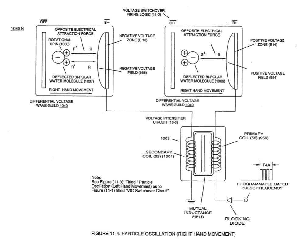
](https://stanslegacy.com/uploads/images/gallery/2023-12/5XYdnHS3orXJUN29-image-1702703150322-05-48.png)
[![image-1702703181359.06.17.png](https://stanslegacy.com/uploads/images/gallery/2023-12/scaled-1680-/drpReUoIHEUG3WYO-image-1702703181359-06-17.png)](https://stanslegacy.com/uploads/images/gallery/2023-12/drpReUoIHEUG3WYO-image-1702703181359-06-17.png)... performing **Voltage Switchover Logic Functions** (B+/B+ / 1030B - B-/B- / 1030A Switchover B-/B- / 1030B - B+/B+ / 1030A) of Figure (11-7) during each and every sequential voltage pulsing cycle (T4A - T4B - T4A - T4B and so on). When (B+/B+ - B-/B- / 1030B) switch function is activated, switch terminals (T1/T2 - T3/T4) are closed. Switch position (T1/T4 - T3/T2) reverses voltage polarity once switch function (T1/T2 - T3/T4) goes to close position after **Switch Logic Function** (1013) becomes an open circuit

... and then vice versa and so on in an repetitive format

... causing "**Particle Oscillation**" as a "**Energy Generator**" by way of "**Physical Stress**" undergoing pulsating "**Electrical Stress**" whenever **pulse switching cycles** (1060) is electrically activated by incoming **trigger pulse frequency** (1019/T4a xxx 1019/T4n), as so illustrated in (1050) of Figure (11-7). [![image-1702703660347.14.18.png](https://stanslegacy.com/uploads/images/gallery/2023-12/scaled-1680-/AZNAM1FWocGf3iEl-image-1702703660347-14-18.png)
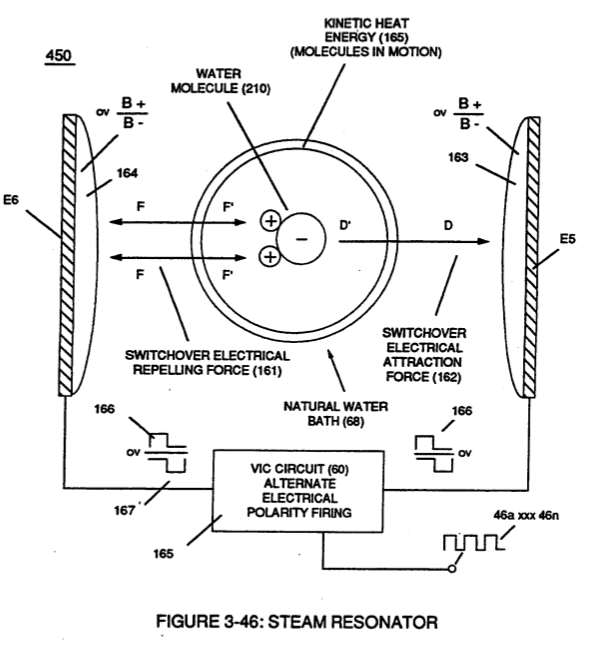
](https://stanslegacy.com/uploads/images/gallery/2023-12/AZNAM1FWocGf3iEl-image-1702703660347-14-18.png)

Oscillating the bipolar water molecule by way of **opposite voltage fields** without amp influxing to heat water on demand, hereby, defines the "Mode of Operability" of the **WFC Steam Resonator**.