.... causing **mutual inductance** (μ1) (*see equations Eq 28 thru Eq 30*) to transform **Distributed Capacitance** (Cda xxx Cdn) of Figure (7-3) of each **inductance coils** (52 - 56 - 62) into a coherent **Voltage Potential** (Yo •..• Vn) equaling the sum of **Voltage Potential** (Vp) developed across each **Pickup Coils** (VpT + Vp1 + Vp2)
| **Distributed Capacitance** (Cda xxx Cdn) of Figure (7-3) [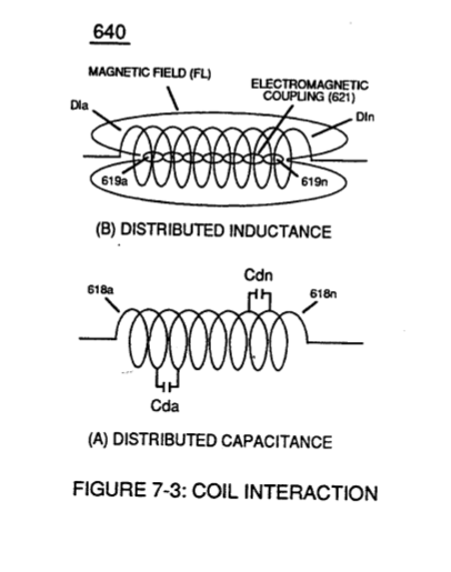](https://stanslegacy.com/uploads/images/gallery/2023-12/LlSOAj47IlZrQIQX-image-1702696921764-21-58.png)[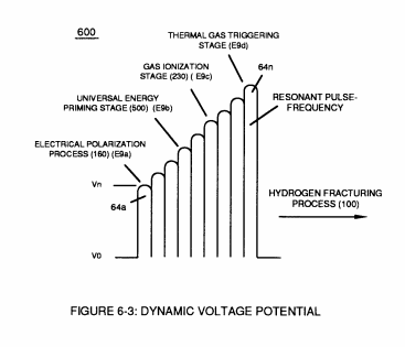](https://stanslegacy.com/uploads/images/gallery/2023-12/LnZPOrM8WkzklnDw-image-1702523261641.png) | equations Eq 28 thru Eq 30
Where, (M) is the **mutual inductance** expressed in the same units as (La), (La) is the total inductance of **Primary coil** (26) and **Secondary coil** (52) with fields aiding. [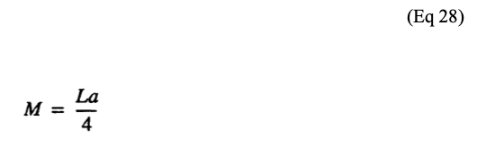](https://stanslegacy.com/uploads/images/gallery/2023-12/orOnPIsU3RdG7LrS-image-1702697017447-23-35.png)**Coupling Inductance** (Rp) between the **Primary coil** (26) and **Secondary Coil** (52) is further extrapolated in the following equation: Where, (Lt) is the **total inductance**, (L1) and L2) are the **inductance** of each individual **transformer coils** (26)(52), (M) is the **mutual inductance** of each **transformer coil** (26/52) being in parallel relationship with fields aiding. [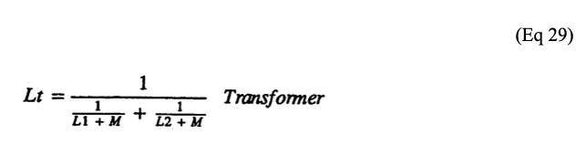](https://stanslegacy.com/uploads/images/gallery/2023-12/T3328JE66oBu2knt-image-1702697029338-23-46.png)**Coupling Inductance** (Rp1) and (Rp2) in (690) of Figure (7-8) is further expressed in the following equation: Where, (Lt cc) is the total inductance of **Choke Coils** (FL1 - FL2), (L1) and (L2) are the **inductance** of each individual **choke coil** (56)(62) in series with **Secondary Coil** (52) **Electrical Voltage Potential** (700) of Figure (7-9) and being exposed to the same **Voltage Transformer** (26 - 53 - 52) **magnetic field** (Rp) with aiding fields, (M) is the **mutual inductance** of **choke coils** (L1/L2) since **Transformer Magnetic Field** (Rp) is the **excitation External Magnetic Field** (Rp1/Rp2) by way of **Unipolar Pulsing Core** (53). [](https://stanslegacy.com/uploads/images/gallery/2023-12/eVVovbgNmXNPgC3a-image-1702697038796-23-56.png) |
... producing **Dynamic Voltage Potential** (600) of Figure (6-3) during repetitive pulsing (49a xxx 49n - T3 - 49a xxx 49n)
... setting up and performing pulsating **Opposite Electrical Attraction Force** (SS' ~ 617 ~ RR' - T3 - SS' ~ 617 - RR') of Figure (7-4) as to **Voltage Dynamics** (220) of Figure (3-29)| **Opposite Electrical Attraction Force** (SS' ~ 617 ~ RR' - T3 - SS' ~ 617 - RR') of Figure (7-4) [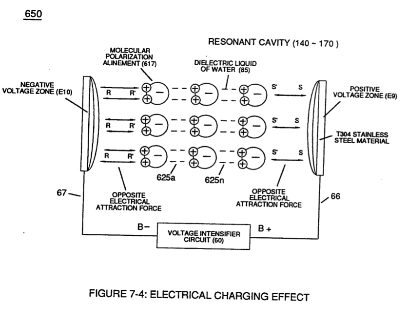](https://stanslegacy.com/uploads/images/gallery/2023-12/30kdftr7xeAN9f0p-image-1702697128032-25-25.png) | **Voltage Dynamics** (220) of Figure (3-29) [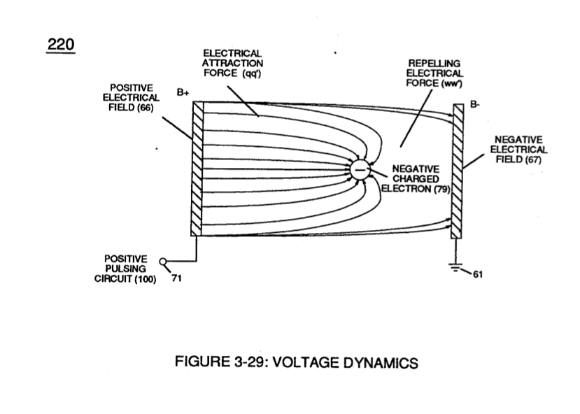](https://stanslegacy.com/uploads/images/gallery/2023-12/61XrnbO4fpkdykfp-image-1702697168227-26-06.png) |
| **Hydrogen Fracturing Process** (90) of Figure (5-5) [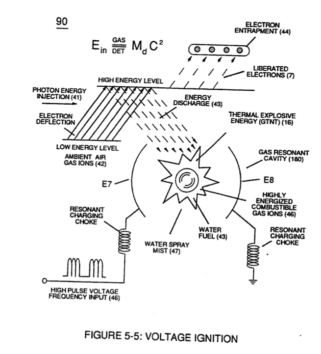](https://stanslegacy.com/uploads/images/gallery/2023-12/P3Y0jSKB2UWLLZWY-image-1702697249097-27-25.png) | (100) of Figure (4-8) [](https://stanslegacy.com/uploads/images/gallery/2023-12/0nCgQtWc7OEumvhA-image-1702697290149-28-07.png) |
| **Taper Resonant Cavity (590) of Figure (6-2)** [](https://stanslegacy.com/uploads/images/gallery/2023-12/iDN6sNT4uVrN1k82-image-1702697335129-28-52.png) | (70) of Figure (4-5) [](https://stanslegacy.com/uploads/images/gallery/2023-12/iQtzw2H4BR15Xg4c-image-1702697308683-28-25.png) |
... allowing, **Voltage Bounce Phenomenon** (700) of Figure (7-9) to be preformed.
| (700) of Figure (7-9) [](https://stanslegacy.com/uploads/images/gallery/2023-12/UY23IAmhCvdRkbPE-image-1702696671415-17-49.png) |
| (52) of Figure (7-8) [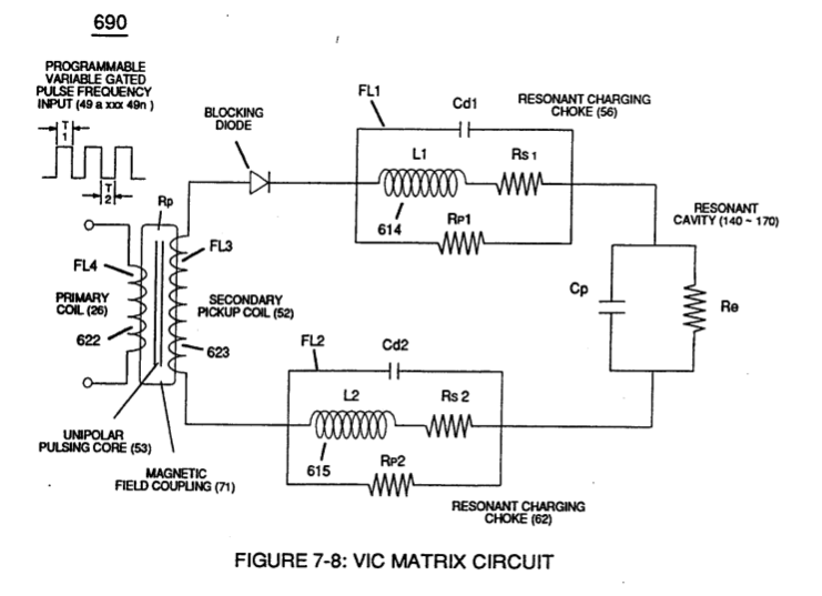](https://stanslegacy.com/uploads/images/gallery/2023-12/yzS6lTm0vWvVpwsS-image-1702696629185-17-03.png) |
Collectively, the resultant **positive electrical charged copper ions** (642a xxx 642n) added together produces **Positive Voltage Potential** (629) being electrically applied to **choke-coil** (56);
whereas, the "Liberated" **negative electrical charged electrons** (641a xxx 641n) added together provides **Negative Voltage Potential** (631) to the opposite end of **Secondary Wire** (52) being electrically connected to **choke coil** (62).
Once **Secondary Coil**-winding (52) is de-energized by the removal (collapsing magnetic field during pulse off-time T2 of external **Magnetic Field** (71), the **dislodged electrons** (641a xx 641n) return to **positive charged copper ions** (642a xx 642n)... terminating and switching off opposite voltage potential (629 - 631) when positive electrical state of the **copper atoms** changes back to net electrical charge of zero.
Sustaining and maintaining the resultant induced **Voltage Potential** (Vo - Vn) without "**Electron Discharged**" (inhibiting electron flow) through **Choke Coil** (62) while, at the same time, inhibiting (preventing) any additional or other electrons from entering into **Secondary copper wire-zone** (52) by way of **Choke Coil** (56) is herein called "**Electron Bounce Phenomenon**" (EbP), as illustrated in (700) of Figure (7-9).
| (700) of Figure (7-9) [](https://stanslegacy.com/uploads/images/gallery/2023-12/UY23IAmhCvdRkbPE-image-1702696671415-17-49.png) |
... causing "**electron clustering**" (641a xxx 641n) to take place within **Copper Wire Zone** (52) during pulse on- time (T1)
... inhibiting "electron flow" to maintain opposite voltage potential (66/E9 \_ 67/E10) across **Resonant Water Gap** (616) during the process of converting water-fuel (85) into instant thermal explosive energy (gtnt) ... therefore, producing a **physical force-yield** (Fy) during gas-ignition (70) of Figure (4-5) which is directly related to the liquid volume of water (85) per injection cycle and applied **Resonant Voltage Intensity** (Yo -Vn), as illustrated in (590) of Figure (6-2) as to (90) of Figure (5-5).| **physical force-yield** (Fy) during gas-ignition (70) of Figure (4-5) [](https://stanslegacy.com/uploads/images/gallery/2023-12/iQtzw2H4BR15Xg4c-image-1702697308683-28-25.png) | (590) of Figure (6-2) [](https://stanslegacy.com/uploads/images/gallery/2023-12/iDN6sNT4uVrN1k82-image-1702697335129-28-52.png) |
| **Traveling Electrical Voltage Wave**-forms (730a - b - c) of Figure (7-12) [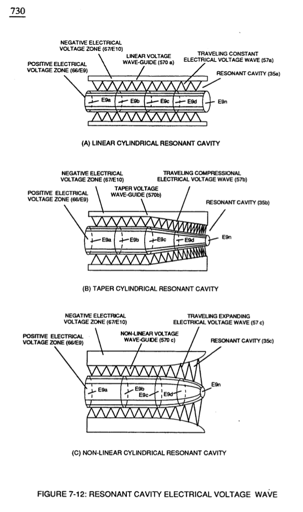](https://stanslegacy.com/uploads/images/gallery/2023-12/apuQHdvTLUsbYOQ2-image-1702698044180-40-41.png) | **Voltage Graph** (750) of Figure (7-14) [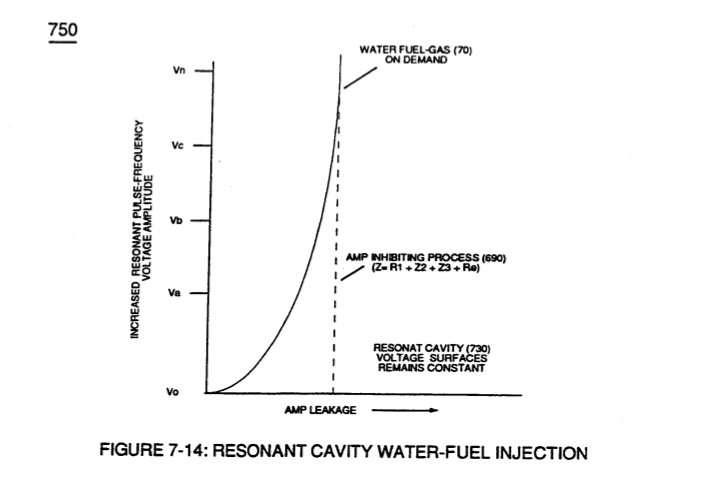](https://stanslegacy.com/uploads/images/gallery/2023-12/1jsle38mbqxsbN9r-image-1702698053508-40-51.png) |