| **Laser Accelerator Assembly** (20) of Figure (3-10) [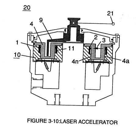](https://stanslegacy.com/uploads/images/gallery/2023-12/0bZIjzhQfoac5KO6-image-1703381224678.png) | **SDP8611 Optoschmitt light receiver** (2) of Figure (3-9) [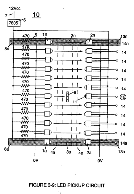](https://stanslegacy.com/uploads/images/gallery/2023-12/eqE5Dz27qkVqIGiU-image-1703374881884.png) |
The peak **wavelength** (3) of Figure (3-9) being transmitted from the infrared emitting diode (led) (1) to the **Optoschmitt receiver** (2) is typically (935 nm) and allows the **Optoschmitt** (2) clock frequency (the speed by which the Optoschmitt changes logic state) to be (100 kHz).
**Optical lens** (4) of Figure (310) redirects and focuses the **transmitted light source** (3) of Figure (3-9) (traveling infrared light waves) to the **Optoschmitt** (2) by passing the light source through a series of **concentric lenses** (4a xxx 4n) of Figure (3-10) which become progressively smaller from the **outer peripheral lens surface** (4a) to the **inner lens surface** (4n). [](https://stanslegacy.com/uploads/images/gallery/2023-12/0bZIjzhQfoac5KO6-image-1703381224678.png)The **spatially concentric lenses** (4a xxx 4n) of Figure (3-10) causes the beam angle of the light source to trigger the **Optoschmitt** (2) beyond the minimum irradiance that is needed to switch the Optoschmitt from **quiescent state** (high logic state I B+ ) to **on-state** (output changing to zero volts).The **Derate linearly** of light intensity is approximately 1.25mWj degree C above 25 degree C at a spatial distance of .500 inches between the **two infrared devices** (1)(2) of Figure (3-9) as to Figure (3-10).
**Transmitted light source** (3) is turned-on when a electrical power source of 5 volts is applied to the **led** (1) through **dropping resister** (5) by way of **voltage regulator** (6) connected to the car **electrical system** (7). Together, the **matched infrared devices** (1)(2) with **optical lens** (4) forms **optical circuit** (8) of Figure (3-9).Grouping additional **optical circuits** (8a xxx 8n) in an inline or linear arrangement, now, forms **Led Pickup Circuit** (10) of Figure (3-9), as shown in Figure assembly (20) of Figure (3-10).
| **Led Pickup Circuit** (10) of Figure (3-9) [](https://stanslegacy.com/uploads/images/gallery/2023-12/eqE5Dz27qkVqIGiU-image-1703374881884.png) | Figure assembly (20) of Figure (3-10) [](https://stanslegacy.com/uploads/images/gallery/2023-12/0bZIjzhQfoac5KO6-image-1703381224678.png) |
Advancing **light-gate** (9) still further performs the same opposite (alternate) logic-state switching in a sequential manner until the advancing **light-gate** (9) reaches the **last optical circuit** (8n).
Reversing the movement of **light gate** (9) performs the same high to low logic switch-function but in reverse sequential order. Reversing the direction of the **light-gate** (9) once again reinstates the original sequential switching order, as illustrated in Figure (3-7) and Figure (3-9).Longevity and reliability of component life is typically 100,000 hours since led pickup circuit (10) of figure (3-9) utilizes no mechanical contacts to perform the sequential logic switch function.
**[](https://stanslegacy.com/uploads/images/gallery/2023-12/0bZIjzhQfoac5KO6-image-1703381224678.png)Light-gate** (9) integrated with **led pickup circuit** (10) make up **Laser Accelerator assembly** (20), as shown in Figure (3-10). **Light-gate** (9) of Figure (3-10) is mechanically linked to the car acceleration pedal by way of **cabling hookup** (22). Opposite placement of the **matched infrared devices** (1)(2) prevents bogus or false triggering of "low" **logic state** (12) during **light-gate displacement** (9a xxx 9n) of Figure (6)(7) and (8). If light emitting diodes (led) (la xxx In) of figure (8) are electrically disconnected from D.C. power supply (6), then **Led Pickup Circuit** (10) outputs are switch to "low" logic state (l2a xxx 12n) which disallows "low" **logic state signal** (12), resulting in a "shut-down" condition to **Hydrogen Gas Control Circuit** (200) of Figure (3-1). [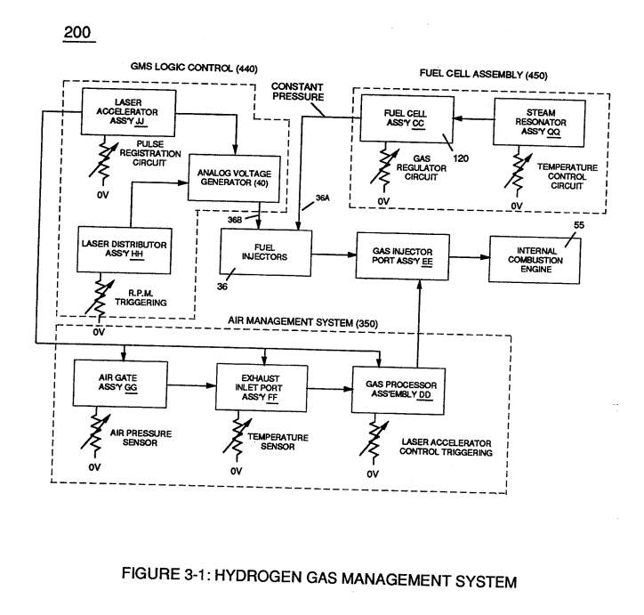](https://stanslegacy.com/uploads/images/gallery/2023-12/2npurKubUvEXMU5s-image-1703381503607.png) Disconnection of **power supply** (6) to **Optoschmitt array** (2a xxx 2n) of Figure (3-9) results in a similar "shut down" condition to **control circuit** (200), as further shown in Figure (3-1).This "shut-down" or "Switch-off" condition helps provide a fail-safe operable **Fuel Cell** (120) of Figure (3-20) by negating acceleration beyond driver's control.