| Figure (1-2) [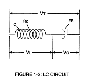](https://stanslegacy.com/uploads/images/gallery/2023-12/VzsK8hdVflGHQSyd-image-1703011673363.png) | Figure (1-1) [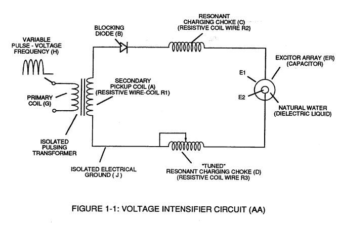](https://stanslegacy.com/uploads/images/gallery/2023-12/qhtqz9LzDjg4722f-image-1703011664617.png) |
... helping to prevent electron flow within the **pulsing circuit** (AA) of Figure 1-1.
[](https://stanslegacy.com/uploads/images/gallery/2023-12/qhtqz9LzDjg4722f-image-1703011664617.png) The **Inductor** (C) takes on or becomes an **Modulator Inductor** which steps up an oscillation of an given charging frequency with the effective capacitance of an pulse-forming network in order to charge the **voltage zones** (E1/E2) to an higher potential beyond applied voltage input. The **Inductance** (C) and **Capacitance** (ER) properties of the LC circuit is therefore "**tuned**" to resonance at a certain frequency.The Resonant Frequency can be raised or lowered by changing the inductance and/or the capacitance values.
The established **resonant frequency** is, of course, independent of voltage amplitude, as illustrated in Figure (1-3) as to Figure (1-4).
| Figure (1-3) [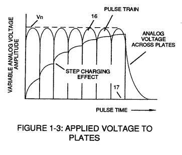](https://stanslegacy.com/uploads/images/gallery/2023-12/KS1IdCNzwsPJRslu-image-1703011682305.png) | Figure (1-4) [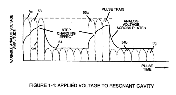](https://stanslegacy.com/uploads/images/gallery/2023-12/BVSJKDz1yh7YR7m9-image-1703011690241.png) |
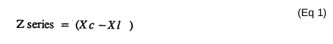
The impedance of an inductor and a capacitor in series, Z series is given by (Eq 1)
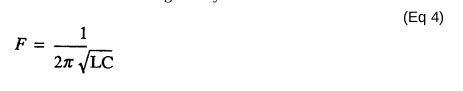
[](https://stanslegacy.com/uploads/images/gallery/2023-12/5kijCBV9DAnEaHJ7-image-1703012652433.png) Where: [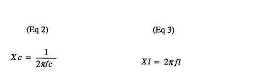](https://stanslegacy.com/uploads/images/gallery/2023-12/WGRmcuSIYoItCgHP-image-1703012669666.png)The Resonant Frequency (F) of an LC circuit in series is given by (Eq 4)
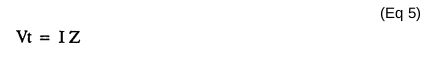
[](https://stanslegacy.com/uploads/images/gallery/2023-12/OG0MPPsrNVExMFqI-image-1703012692611.png)Ohm's Law for LC circuit in series is given by:
[](https://stanslegacy.com/uploads/images/gallery/2023-12/YlXMelnpzpt0EBZg-image-1703012708035.png)