At frequency close to resonance, the voltage across the individual components is higher than the applied voltage (H),
and, at **resonant frequency**, the voltage VT across both the **inductor** and the **capacitor** are *theoretically infinite*.
However, **physical constraints** of components and **circuit interaction** prevents the voltage from reaching infinity.
The voltage (VL) across the inductor (C) is given by the equation (Eq 6) [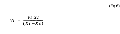](https://stanslegacy.com/uploads/images/gallery/2023-12/CZZWea4p0NaEqwRU-image-1703012863032.png) The voltage (VC) across the capacitor is given by (Eq 7) [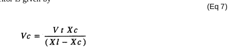](https://stanslegacy.com/uploads/images/gallery/2023-12/6egjXbId58fGa3UB-image-1703012889070.png) During **resonant interaction**, the incoming unipolar **pulse-train** (H) of Figure (1-1) as to Figure (1-5) produces a **step-charging voltage-effect** across **Excitor-Array** (ER), as illustrated in Figure (1-3) and Figure (1-4).| Figure (1-1) [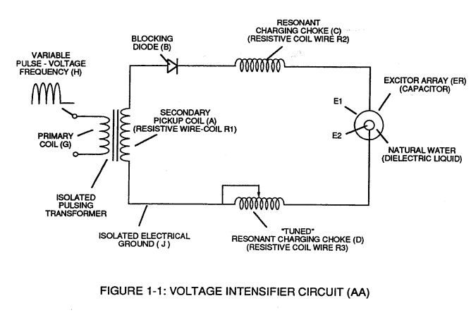](https://stanslegacy.com/uploads/images/gallery/2023-12/qhtqz9LzDjg4722f-image-1703011664617.png) | Figure (1-5) [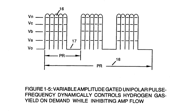](https://stanslegacy.com/uploads/images/gallery/2023-12/l7jnV5JDH3YDsfqc-image-1703011705003.png) |
| Figure (1-3) [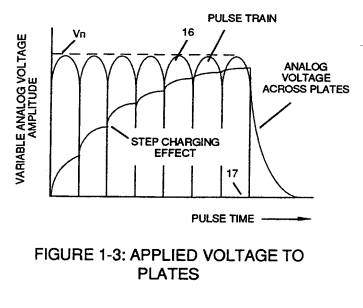](https://stanslegacy.com/uploads/images/gallery/2023-12/KS1IdCNzwsPJRslu-image-1703011682305.png) | Figure (1-4) [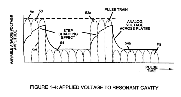](https://stanslegacy.com/uploads/images/gallery/2023-12/BVSJKDz1yh7YR7m9-image-1703011690241.png) |
Voltage intensity increases from zero '**ground-state**' to a **high positive voltage potential** in an progressive function.
Once the voltage-pulse is terminated or **switched-off**, voltage potential returns to "**ground-state**" or near ground-state, to start the voltage deflection process over again.Voltage intensity or level across **Excitor-Array** (ER) can ***exceed 20,000 volts*** due to circuit (AA) interaction and is directly related to **pulse-train** (H) variable amplitude input.