# Quenching Nozzle

Additional Quenching Circuits arranged in a Disc-shape configuration forms a "Quenching Nozzle" when attached to an "Quenching Tube", as illustrated in Figure (2-4) as to Figure (2-6).

Figure (2-3) [![image-1702961652974.54.10.png](https://stanslegacy.com/uploads/images/gallery/2023-12/scaled-1680-/vHikAM9oiGf9RNxB-image-1702961652974-54-10.png)
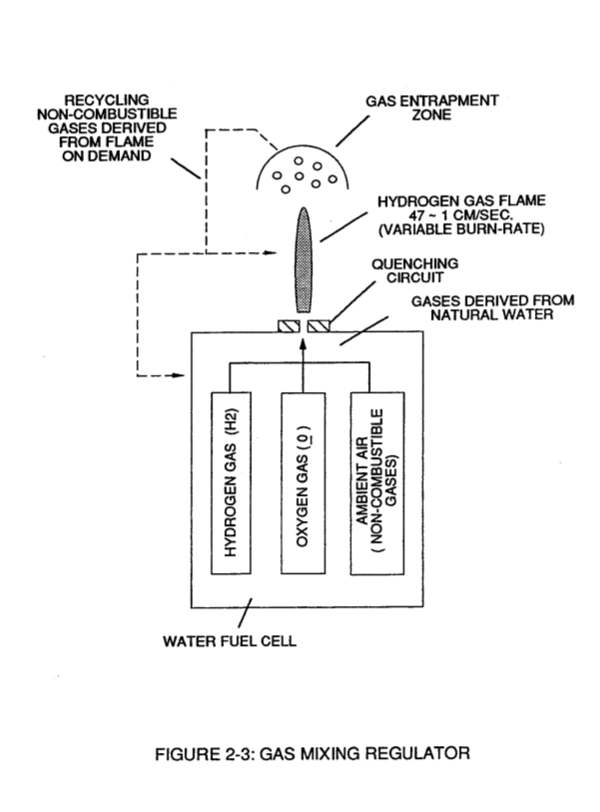
](https://stanslegacy.com/uploads/images/gallery/2023-12/vHikAM9oiGf9RNxB-image-1702961652974-54-10.png) Figure (2-6) [![image-1702961676853.54.34.png](https://stanslegacy.com/uploads/images/gallery/2023-12/scaled-1680-/7UGJBw4kZB7ddVvy-image-1702961676853-54-34.png)
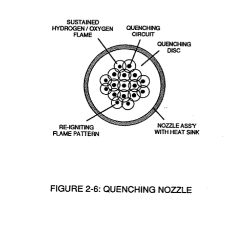
](https://stanslegacy.com/uploads/images/gallery/2023-12/7UGJBw4kZB7ddVvy-image-1702961676853-54-34.png)
The **Multi Gas-Port Disc** compensates for increased **Gas-Velocity** while "preventing" spark-ignition of the **Fuel-Cell** gases. The overlapping **Flame-Pattern** re-ignites the expelling hydrogen gas-mixture (B/D) should **Flame-Out** occur. Ceramic material is used to form the "**Quenching Disc**" to "prevent" hole-size enlargement due to gas-oxidation. The non-combustible gases (D) keeps the **Ceramic Material** "cool-to-the-touch" by projecting the **Gas-Flame** beyond and away from the disc-surface ... the **Quenching Disc** remains "cool" even if the Gas-Flame Temperature exceeds the melting-point of the disc-material.