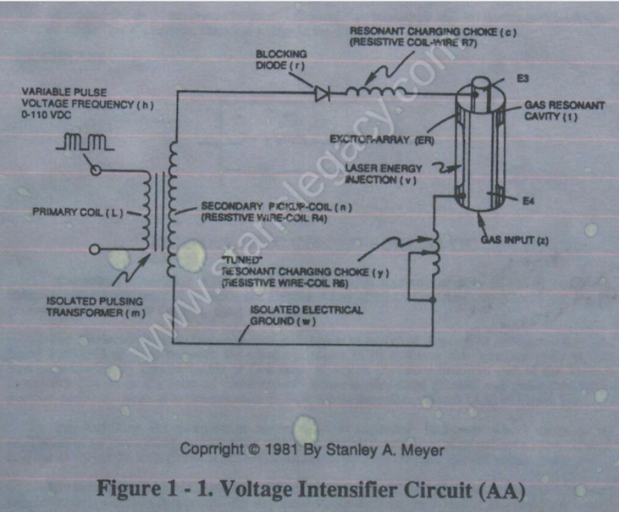
# RLC CIRCUIT

The **voltage** (<span class="katex"><span class="katex-mathml">V<sub>C</sub></span><span aria-hidden="true" class="katex-html"><span class="base"><span class="mord"><span class="msupsub"><span class="vlist-t vlist-t2"><span class="vlist-r"><span class="vlist-s">​</span></span></span></span></span></span></span></span>) across the capacitor is given by:

[![image-1729956608556.png](https://stanslegacy.com/uploads/images/gallery/2024-10/scaled-1680-/cO76K1Io59yaGKdl-image-1729956608556.png)](https://stanslegacy.com/uploads/images/gallery/2024-10/cO76K1Io59yaGKdl-image-1729956608556.png)

During resonant interaction, the incoming **unipolar pulse-train** (h) of Figure (1-1) as to Figure (9B) produces an step-charging voltage-effect across **Excitor-Array** (ER of t), as illustrated in Figure progressive function.

<table border="1" id="bkmrk-figure-9b" style="border-collapse: collapse; width: 100%;"><tbody><tr><td class="align-center" style="width: 45.9821%;">![image-1729909060083.png](https://stanslegacy.com/uploads/images/gallery/2024-10/scaled-1680-/KHbfbIn48c46IpBu-image-1729909060083.png)Figure 1-1</td><td style="width: 54.0179%;">[![image-1729955474738.png](https://stanslegacy.com/uploads/images/gallery/2024-10/scaled-1680-/jnFTXU8GBiPIjwpf-image-1729955474738.png)
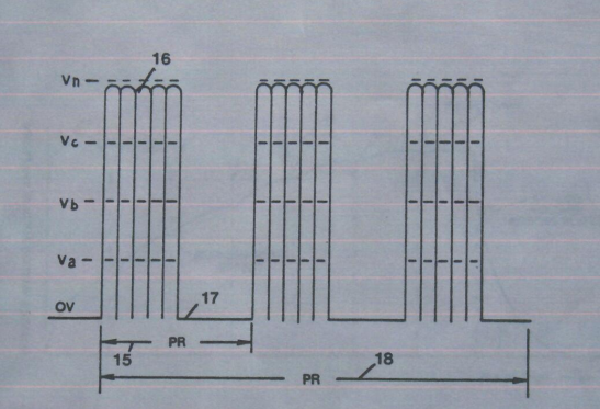
](https://stanslegacy.com/uploads/images/gallery/2024-10/jnFTXU8GBiPIjwpf-image-1729955474738.png)

Figure 9B

</td></tr></tbody></table>

Once the voltage-pulse is terminated or shut-off, voltage potential returns to an "ground-state" or near ground-state to start the voltage deflection process over again.

<p class="callout danger">Voltage intensity or level across **Excitor-Array** (*ER of t*) can exceed 20,000 volts due to **circuit** (AA) interaction and is <span style="text-decoration: underline;">directly related</span> to **pulse-train** (h) variable amplitude input.</p>

#### RLC CIRCUIT

**Inductor (c)** is made of or composed of **resistive wire** (R7) to further restrict D.C. current flow beyond **inductance reaction** (XL), and is given by

[![image-1729957184564.png](https://stanslegacy.com/uploads/images/gallery/2024-10/scaled-1680-/tMbmcRV4nVm5Pmqf-image-1729957184564.png)
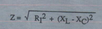
](https://stanslegacy.com/uploads/images/gallery/2024-10/tMbmcRV4nVm5Pmqf-image-1729957184564.png)

#### Dual-inline RLC NETWORK

Variable **inductor-coil** (y), similar to **inductor** (c) connected to **opposite polarity voltage zone** (E4) further inhibits electron movement or deflection within the Voltage Intensifier Circuit.

<p class="callout info">Moveable wiper arm fine “tunes” "**Resonant Action"** during pulsing operations.</p>

**Inductor** (y) in relationship to **inductor** (c) electrically balances the opposite voltage electrical potential across voltage zones (E3/E4).

#### VIC RESISTANCE

Since **pickup coil** (n) is also composed of or made of **resistive wire-coil** (R4), then, total circuit resistance is given by

[![image-1729957065211.png](https://stanslegacy.com/uploads/images/gallery/2024-10/scaled-1680-/0VNxGIFmANBN7u7A-image-1729957065211.png)
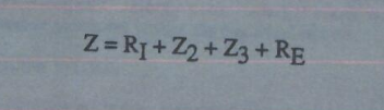
](https://stanslegacy.com/uploads/images/gallery/2024-10/0VNxGIFmANBN7u7A-image-1729957065211.png)

Where, <span class="katex"><span class="katex-mathml">R<sub>E</sub></span><span aria-hidden="true" class="katex-html"><span class="base"><span class="mord"><span class="msupsub"><span class="vlist-t vlist-t2"><span class="vlist-r"><span class="vlist-s">​</span></span></span></span></span></span></span></span> is the dielectric constant of **Argon** (Ar).