# Transformer Action
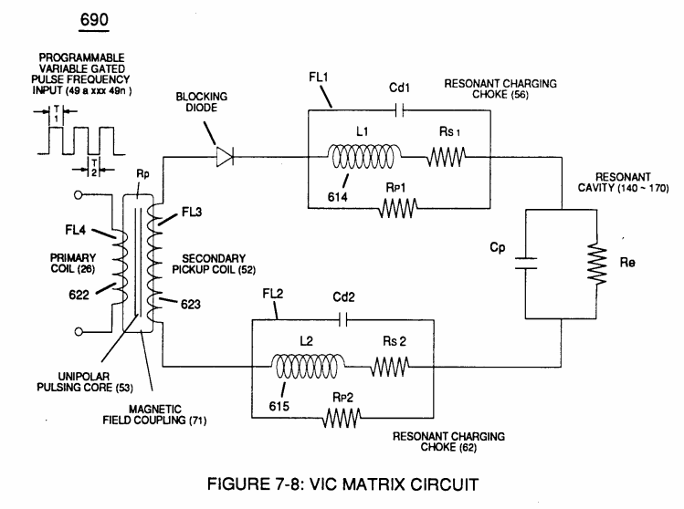
**Inductance Core** (53) of Figure (6-1) composed of "**Grain Oriented**" Electrical Steel laminations step up applied **Voltage** (49) when **Magnetic Field Coupling** (71) of Figure (7-8) cross over to **Secondary Pickup Coil**-winding (52) which has more turns of wire than **Primary Coil-** winding (26) by way of "**Eddy**" currents that induce magnetic flux lines of forces (71a xxx 71n) emanating away from magnetic core material (53) and caused by **Primary Coil** (26) being electrically energized during pulsing operations (T1a xx T1n), as illustrated in (690) of Figure (7-8).
**Magnetic Induction** (71a - 71n) is determined by **Inductance Permeability** (μL) of core material (53) along with VIC circuit geometry ability to step up **Voltage Potential** (Vo - Vn) by way of "**Transformer Action**", and is expressed in the following equations:
[](https://stanslegacy.com/uploads/images/gallery/2023-12/XSHM5TpNJbvKWdwg-image-1702446091555.png)
**Where**,
[](https://stanslegacy.com/uploads/images/gallery/2023-12/nQymCnRuuu9kwxZK-image-1702523026667.png)(Ep) is voltage induced in Primary Coil (26),
(Es) is Voltage induced in Secondary Coil (52),
(Np) is the number of turns of wire that make up **Primary Coil-Wrap** (504) of Figure (6-1),
(Ns) is the **number of turns** of wire that make up **Secondary Coil-Wrap** (505) of Figure (6-1),
(Is) is the established current flow (**under load**) in **Secondary Coil-Winding** (52) ,
(Ip) is the amount of current flow in the **Primary Coil-Winding** (26) when electrically "energized" during pulsing operations (49a xxx 49n - T3 - 49a xxx 49a).
The turns ratio of the **VIC Transformer** (26/52) is determined by the following equation:
[](https://stanslegacy.com/uploads/images/gallery/2023-12/0FfSa2XjWgyWvDtp-image-1702446102303.png)
**Where**,
(Ns) is the number of turns of wire for each bobbin cavity (505) of Figure (6-1) as to (710) of Figure (7-10) that are electrically connected in series arrangement (505a xxx 505n) to form **Secondary** **Coil-Wrap** (52),
(Np) is the number of turns of the **Primary Coil** (26) wire-wrapped about spool cavity (504)
[](https://stanslegacy.com/uploads/images/gallery/2023-12/lQrzUXSnbY5rtQb2-image-1702595344873.png)... each bobbin cavity adhering to equation (Eq 20), as illustrated in (710) of Figure (7-10).
The **impedance ratio** of VIC transformer is determined by:
[](https://stanslegacy.com/uploads/images/gallery/2023-12/d2LspWrLSsIZZ8i0-image-1702446118191.png)
**Where**,
(1'2) is the sum of the magnetic field strength (FL4) of the **primary coil** (26) and the **induced magnetic field** (FL3) of the **Secondary Pickup Coil** (52) during each pulse cycle (T1) in direct relationship to repetitive pulse cycling (T1a xxx T1n) and both magnetic fields (FL3/FL4) interacting, and is expressed in the following equation:
[](https://stanslegacy.com/uploads/images/gallery/2023-12/2BG3s0gDGp33Yygq-image-1702446130639.png)
**Where**,
(M) is the mutual inductance expressed in the same units .as (La),
(La) is the total inductance of **Primary coil** (26) and Secondary coil (52) with fields aiding **Coupling Inductance** (Rp) between the **Primary coil** (26) and **Secondary Coil** (52) is further extrapolated in the following equation:
[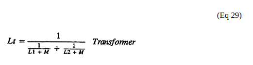](https://stanslegacy.com/uploads/images/gallery/2023-12/cT0wusDcHXsvGdp5-image-1702446153461.png)
**Where**,
(Lt) is the total inductance,
(L1) and L2) are the inductances of each individual transformer coils (26)(52),
(M) is the mutual inductance of each transformer coil (26/52) being in parallel relationship with fields aiding **Coupling Inductance** (Rp1) and (Rp2) in (690) of Figure (7-8) is further expressed in the following equation:
[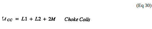](https://stanslegacy.com/uploads/images/gallery/2023-12/Eyi5pwuUvYxixdvm-image-1702446178855.png)
**Where**,
(Lt cc) is the total inductance of **Choke Coils** (FL1 - FL2),
(L1) and (L2) are the inductances of each individual choke coil (56)(62) in series with **Secondary Coil** (52) **Electrical Voltage**
**Potential** (700) of Figure (7-9) and being exposed to the same **Voltage Transformer** (26 - 53 - 52) magnetic field (Rp) with aiding fields,
(M) is the mutual inductance of choke coils (L1/L2) since **Transformer Magnetic Field** (Rp) is the excitation **External Magnetic Field** (Rp1/Rp2) by way of **Unipolar Pulsing Core** (53).
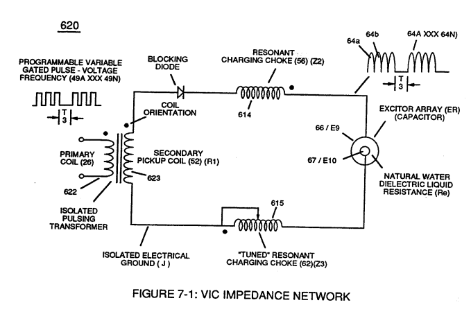
**VIC Coil Assembly** (580) of Figure (6-1) as to (690) of Figure (7-8) in reference to **Schematic Circuit** (620) of Figure (7-1) is constructed in such a way as to rotate and position **Inductor Coils** (26 - 52 - 56 - 62) to be of the same electromagnetic polarity orientation, indicator mark (e)
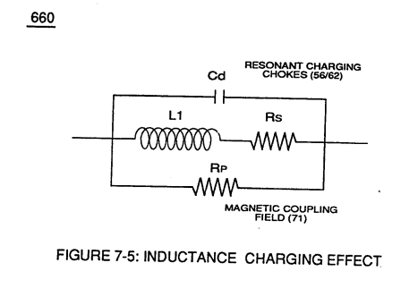
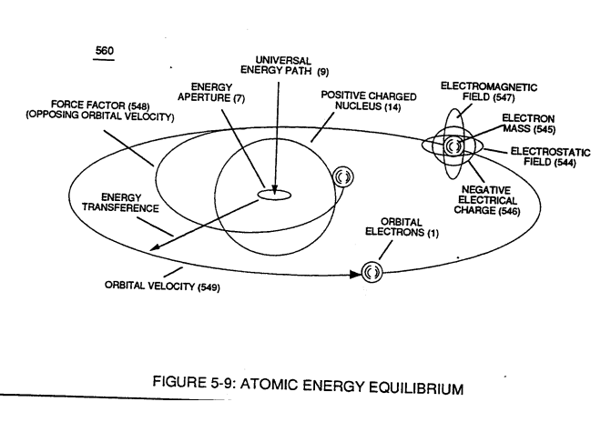
... thus, allowing **Inductance Fields** (FL1 - FL2 - FL3 - FL4) to be aiding one another during the same sequence of pulse-time (T1) ... thereby, allowing **Inductance Charging Effect** (660) of Figure (7-5) and **Resonant Voltage Effect** (670) of Figure (7-6) to interact with the dielectric properties of water (Re) to cause and inhibit electron flow (IF) since "electrons" magnetic field (547) of Figure (5-9) locks onto the electromagnetic fields of each energized choke coils (FL1/FL2) during **Voltage Excitation** (Vo -Vn) which, now, brings on and allows "**Electron Bounce Phenomenon**" (700) of Figure (7-9) to take place.
| **Inductance Charging Effect** (660) of Figure (7-5)
[](https://stanslegacy.com/uploads/images/gallery/2023-12/OJ4oQWHq5REb8uVE-image-1702595636154.png)
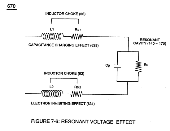
| **Resonant Voltage Effect** (670) of Figure (7-6)
[](https://stanslegacy.com/uploads/images/gallery/2023-12/F8SiHklu1rTCr0kf-image-1702595646541.png)
|
| (547) of Figure (5-9)
[](https://stanslegacy.com/uploads/images/gallery/2023-12/VTmtI7b0eETTHgBj-image-1702595664580.png)
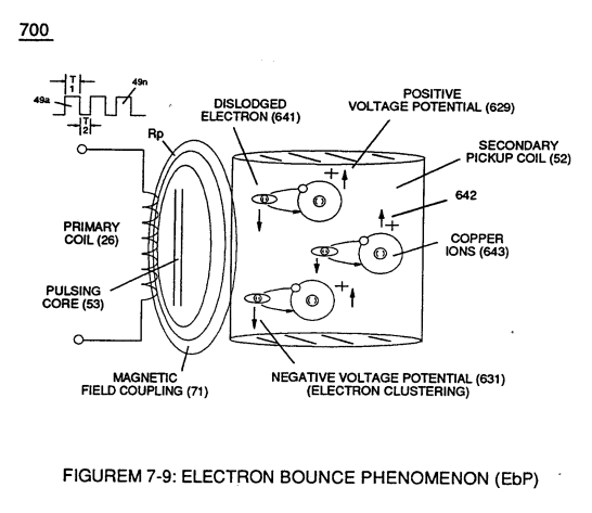
| **(700) of Figure (7-9)**
[](https://stanslegacy.com/uploads/images/gallery/2023-12/SIOmTh50yR29ICJg-image-1702595681532.png)
|
(See Appendix B Note 1)
> **Note 1**) The **Electron Inhibiting Effect** (631) of Figure (7-6) to cause "**Electron Clustering**" (Grouping/collecting negative charged particles at a given point) (700) of Figure (7-9) to produce ''**Negative Voltage Potential**" ( B- ) at one side of **Water Gap** (Cp) of Figure (7-8) is accomplished by low electrical power input (Tab 38) when **Choke-Coil** (62) of Figure (7-1) magnetic field (FL2) (690) of Figure (7-8) during pulse on-time (49) impede "**Electron-Flow**" since electron mass is composed of electromagnetic matter which interacts with magnetic field strength (FL2).
>
> **Capacitance Charging Effect** (628) prevents amp influxing away from **Water Gap** (Cp) in a similar manner
>
> ... producing "**Electrical Stress**" (SS' - RR') (B+/B-) across **Water Gap** (Cp) since *both* **Choke-Coils** (56/62) conduct voltage potential (*Negative or Positive*) during pulsing operations.
| **Electron Inhibiting Effect** (631) of Figure (7-6)
[](https://stanslegacy.com/uploads/images/gallery/2023-12/FWz40QLyPOJwJefG-image-1702595701485.png)
| "**Electron Clustering**" (Grouping/collecting negative charged particles at a given point) (700) of Figure (7-9)
[](https://stanslegacy.com/uploads/images/gallery/2023-12/SIOmTh50yR29ICJg-image-1702595681532.png)
|
| **''Negative Voltage Potential"** ( B- ) at one side of Water Gap (Cp) of Figure (7-8) & magnetic field (FL2) (690) of Figure (7-8)
[](https://stanslegacy.com/uploads/images/gallery/2023-12/buC0CBJSdthSkou3-image-1702593978530.png)
| **Choke-Coil** (62) of Figure (7-1)
[](https://stanslegacy.com/uploads/images/gallery/2023-12/ZpW3wOEzH7FjjjUD-image-1702595741313.png)
|