| Figure (3-5) [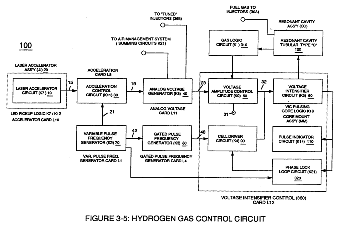](https://stanslegacy.com/uploads/images/gallery/2023-12/d5x6lw5jRAJT48i1-image-1703195613050.png) | Figure (3-16) [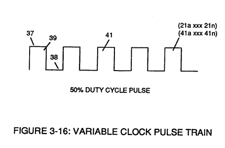](https://stanslegacy.com/uploads/images/gallery/2023-12/9eo48JVGQNzatQ86-image-1703198042496.png) |