| Figure (3-21) [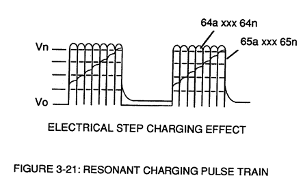](https://stanslegacy.com/uploads/images/gallery/2023-12/uie7yJbd501dcf86-image-1703197617452.png) | Figure (3-22) [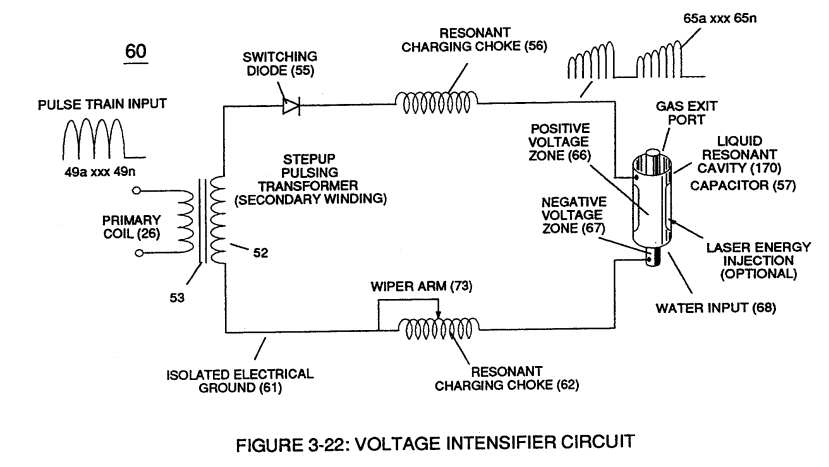](https://stanslegacy.com/uploads/images/gallery/2023-12/QHMK3ysi5cLB805A-image-1703197630289.png) |
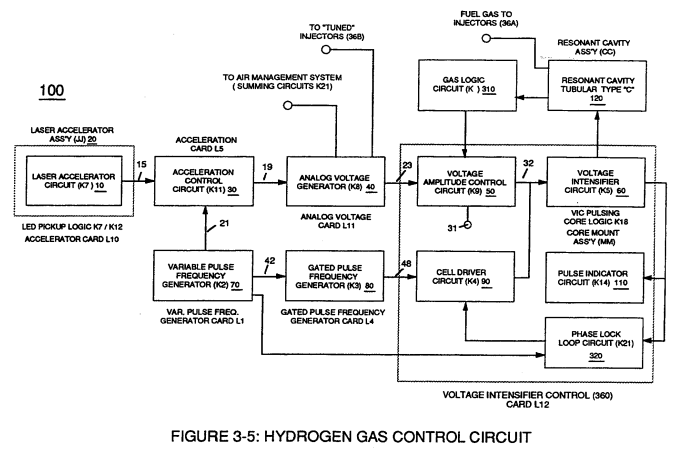
**Regulator stage** (27) of **circuit** (50) converts **battery voltage potential** (29) of Figure (3-6) via **electrical terminal** (31) of Figure (3-5) as to Figure (3-6) into a **analog voltage signal** (32) of Figure (3-15) which corresponds to but is **electrically isolated** (*crossover voltage from two separate power supplies*) from incoming **gas volume signal** (23) of Figure (3-14), as shown in Figure (35).
**Variable voltage range** (32a xxx 32n) from **one** (1) up to **twelve** (12) volts (regulating battery voltage) is applied across **primary coil** (26) of **Voltage Intensifier Circuit** (60) of Figure (3-21). Second **regulator stage** (28) simply acts and function as a **gas regulator** (33) by preventing **Fuel Gas** production beyond a predetermined **gas pressure level** (34) of Figure (3-15) during **Fuel Cell** operations and, as such, maintains constant gas pressure to **Fuel Injectors** (36) of Figure (3-1) regardless of engine performance (R.P.M. response).If for example, **Fuel Gas** production is greater than demand, then, **analog signal** (32) is reduced to proper **voltage level** (35) (voltage level directly determines gas pressure via **Resonant Action**) required to maintain **gas pressure** (34).
Conversely, **analog signal** (32) is always allowed to exceed **voltage level** (35) during **injection** (36) of Figure (3-1) until **gas-point** (34) is reached.In cases where **linear voltage** (32) drops (descending value) below **gas-point** (35) then **gas regulator stage** (28) increases **voltage amplitude** (32a xxx 32n) (analog voltage) to **voltage point** (35).
If **gas pressure** (34a xx) should exceed **gas point** (35) during injector off-time, **gas pressure release valve** (75) of Figure (3-24) (**gas venting** 37 of Figure 3-15) expels **Fuel gases** (88) until **gas point** (34) is either reached or a delay timing circuit activates **Safety Control Circuit** (14) of Figure (3-6) which, in turns, switches off or disconnects **applied electrical power** (28) to **Fuel Cell electrical system** (400) of Figure (3-6).| Figure (3-15) [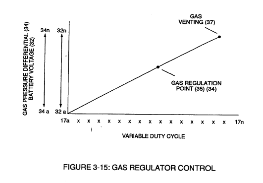](https://stanslegacy.com/uploads/images/gallery/2023-12/q8NhrnLpRbNYf6ta-image-1703197371585.png) | Figure (3-6) [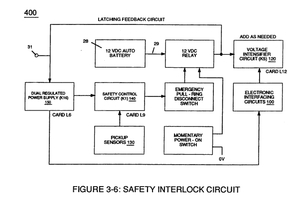](https://stanslegacy.com/uploads/images/gallery/2023-12/svIAaiYbAQpJY3rv-image-1703197390102.png) |
| Figure (3-1) [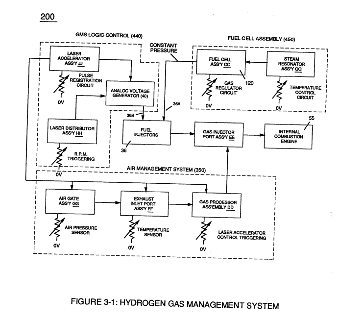](https://stanslegacy.com/uploads/images/gallery/2023-12/QW9gvbrkDyzcsRDF-image-1703197200823.png) | Figure (3-24) [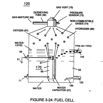](https://stanslegacy.com/uploads/images/gallery/2023-12/1WXhsCSuTnngaFfo-image-1703197217269.png) |
In terms of operability, **Laser Accelerator Assembly** (20) of Figure (3-5) is, now, attenuating **battery voltage potential** (32a xxx 32n) which is electrically connected to **Voltage Intensifier Circuit** (60) of Figure (3-5).
[](https://stanslegacy.com/uploads/images/gallery/2023-12/d5x6lw5jRAJT48i1-image-1703195613050.png)