| Figure (3-15) [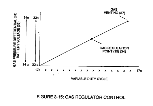](https://stanslegacy.com/uploads/images/gallery/2023-12/q8NhrnLpRbNYf6ta-image-1703197371585.png) | Figure (3-18) [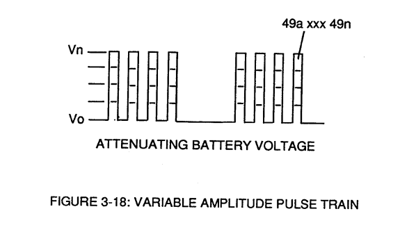](https://stanslegacy.com/uploads/images/gallery/2023-12/perOMBdYqG5zfDB2-image-1703200544967.png) |
| Figure (3-19) [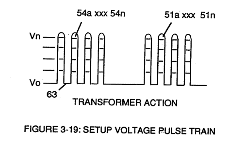](https://stanslegacy.com/uploads/images/gallery/2023-12/ojTv41ralWh4qvQC-image-1703203837958.png) | Figure (3-22) [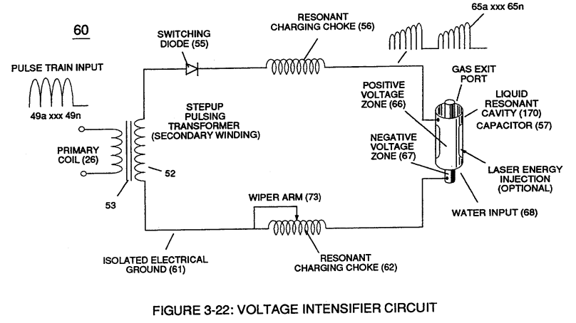](https://stanslegacy.com/uploads/images/gallery/2023-12/K7QoIRjYjGqOS8C3-image-1703201617139.png) |
**Analog voltage signal** (32a xxx 32n) of Figure (3-15) allows **pulse train** (51a xxx 51n) **voltage amplitude** (V0 xxx Vn) of Figure (3-19) to vary from **one** up to **twelve** volts *(battery supply 28 of Figure 3-6* by attenuating **Laser Accelerator circuit** (10) of Figure (3-5) via **Hydrogen Gas Control Circuit** (100).
| Figure (3-15) [](https://stanslegacy.com/uploads/images/gallery/2023-12/q8NhrnLpRbNYf6ta-image-1703197371585.png) | Figure (3-5) [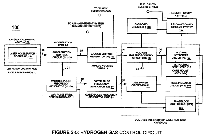](https://stanslegacy.com/uploads/images/gallery/2023-12/d5x6lw5jRAJT48i1-image-1703195613050.png) |
**Variable pulse frequency generator** (70) of Figure (3-5) varies and adjusts **pulse frequency** (63) *(50% duty cycle pulse)* while **gated pulse frequency generator** (80) of Figure (3-5) varies and adjusts **pulse width** (54a xxx 54n).
These controlled and variable pulse features are, now, translated to **Resonant Charging pulse train** (65a xxx 65n) of Figure (3-21) via **Unipolar pulse train** (64a xxx 64n) of Figure (3-20) during **Resonant Action** (160) of Figure (3-26) when signal coupling is applied across **Resonant Cavity** (170) of Figure (3-24) via **positive voltage zone** (66).| Figure (3-21) [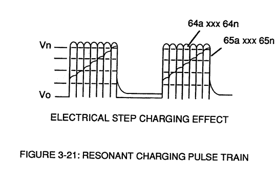](https://stanslegacy.com/uploads/images/gallery/2023-12/qZcJcpsQWujxY3uB-image-1703202650133.png) | Figure (3-20) [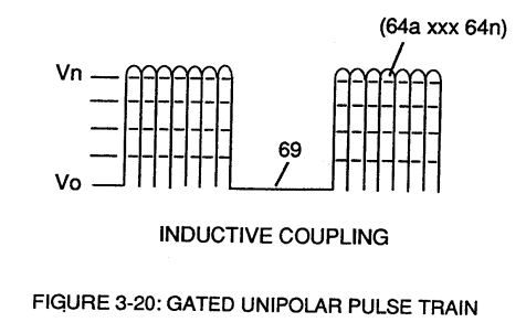](https://stanslegacy.com/uploads/images/gallery/2023-12/1uHRCvzqaVhAKGH6-image-1703204498070.png) |
| Figure (3-26) [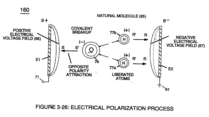](https://stanslegacy.com/uploads/images/gallery/2023-12/JEtePO4SKkPGZWRI-image-1703203395676.png) | Figure (3-24) [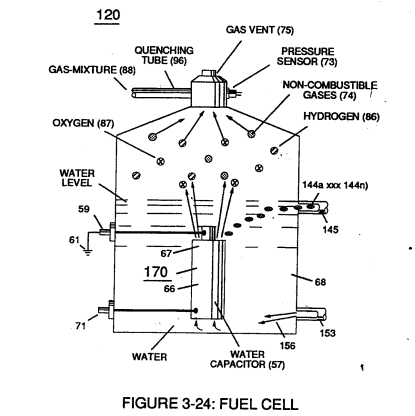](https://stanslegacy.com/uploads/images/gallery/2023-12/SfsY9Ms8MRP5eM0o-image-1703197304479.png) |
**Negative electrical voltage potential** (61) of **pulse wave** (65a xxx 65n) of Figure (3-21) is simultaneously applied to **negative voltage zone** (67) via **Resonant Charging Choke** (62) of Figure (3-22) which is electrically linked to opposite end of **Primary Coil** (26).
The resultant **signal coupling** ( 65a xx 65n ) of Figure (3-21) is accomplished since **primary coil** (26), **pulsing core** (53), **secondary coil** (52), **switching diode** (55), **resonant charging choke** (56), **resonant cavity assembly** (170), **natural water** (68), and **variable resonant charging choke** (62) forms **Voltage Intensifier Circuit** (60) of Figure (3-22), as illustrated in Figure (3-22) as to Figure (3-23).
| Figure (3-22) [](https://stanslegacy.com/uploads/images/gallery/2023-12/K7QoIRjYjGqOS8C3-image-1703201617139.png) | Figure (3-23) [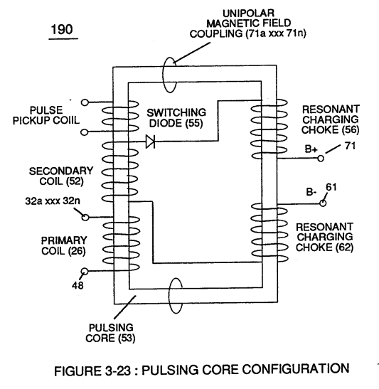](https://stanslegacy.com/uploads/images/gallery/2023-12/Tus1Xr1U62DJCsDx-image-1703201534713.png) |
**Negative electrical ground** (61) of **voltage Intensifier circuit** (60) of Figure (3-22) is electrically isolated from **primary electrical ground** (48) of Figure (3-22).
**Pulsing transformer** (26/52) of Figure (3-22) steps up voltage amplitude or **voltage potential** (Vo xxx Vn) of Figure (3-19) during pulsing operations. **Primary coil** (26) is electrically isolated (*no electrical connection between primary 26 and secondary coil)* to form **Voltage Intensifier Circuit** (60) of Figure (3-22). Voltage amplitude or **voltage potential** (Vo xxx Vn) is increased when **secondary coil** (52) is wrapped with more turns of wire.**Isolated electrical ground** (61) prevents electron flow from **input circuit ground** (48).
**[](https://stanslegacy.com/uploads/images/gallery/2023-12/K7QoIRjYjGqOS8C3-image-1703201617139.png)Switching diode** (55) of Figure (3-22) not only acts as a blocking diode by preventing electrical "**shorting**" to **secondary coil** (52) during **pulse off-time** (69) of Figure (3-20) since **diode** (55) "only" conducts electrical energy in the direction of schematic arrow; but, also, and at the same time functions as an **electronic switch** which opens **electrical circuit** (60) during **pulse off-time** ...allowing magnetic fields of both **inductor coils** (56/57) to collapse ... forming **pulse train** (64a xxx 64n).**Resonant charging choke** (56) in series with **Excitor-Array** (160) of Figure (25) forms an **inductor-capacitor circuit** (180) of Figure (3-28) since **Excitor-Array** (66/67) acts and performs as a capacitor (*dielectric liquid between opposite electrical plates*) during pulsing operations.
[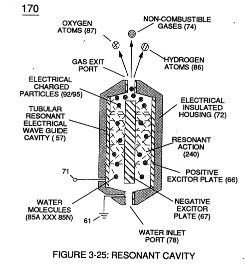](https://stanslegacy.com/uploads/images/gallery/2023-12/jmc1Z2WkjHNbWiZ6-image-1703201429384.png)The **dielectric properties** (*insulator to the flow of amps*) of **natural water** (68) of Figure (3-28) as to Figure (3-26) > *(dielectric constant of water being 78.54 @ 20C in 1-atm pressure)* between **electrical plates** (66/67) forms **capacitor** (57), as illustrated in (170) of Figure (3-25).| Figure (3-26) [](https://stanslegacy.com/uploads/images/gallery/2023-12/JEtePO4SKkPGZWRI-image-1703203395676.png) | Figure (3-28) [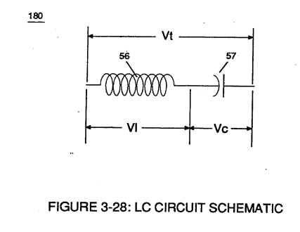](https://stanslegacy.com/uploads/images/gallery/2023-12/8IJsOVAmLG4LJk6U-image-1703203073889.png) |
Water now becomes part of **Voltage Intensifier circuit** in the form of "**resistance**" between **electrical ground** (67) and **pulse-frequency positive potential** (66) ... helping to prevent electron flow within **pulsing circuit** (60) of Figure (3-22).
**Inductor** (56) and **capacitor** (57) properties of LC circuit (180) is therefore "**tuned**" to resonate at a given frequency. **Resonant frequency** (63) of Figure (3-19) can be raised or lowered by changing the **inductance** (56) and/or **capacitance** (57) **valves**.The established **resonant frequency** is, of course, independent of voltage amplitude, as illustrated in Figure (3-21) as to Figure (3-18).
| Figure (3-21) [](https://stanslegacy.com/uploads/images/gallery/2023-12/qZcJcpsQWujxY3uB-image-1703202650133.png) | Figure (3-18) [](https://stanslegacy.com/uploads/images/gallery/2023-12/perOMBdYqG5zfDB2-image-1703200544967.png) |
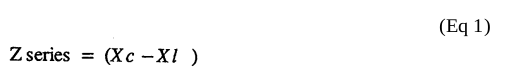
The impedance of **inductor** (56) and **capacitor** (57) in series, Z series is given by (Eq 1)
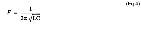
[](https://stanslegacy.com/uploads/images/gallery/2023-12/6bTQI1dpHoy0l7Xk-image-1703202839633.png)where **Resonant frequency** (63) of LC circuit in series is given by (Eq 4)
[](https://stanslegacy.com/uploads/images/gallery/2023-12/m9WaOO0dqMhRUide-image-1703202762309.png)Ohm's law of LC circuit (180) of Figure (3-28) in series is given by (Eq 5)
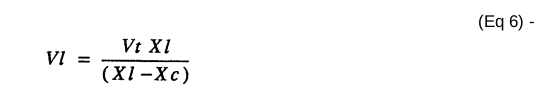
[](https://stanslegacy.com/uploads/images/gallery/2023-12/yGrIzleU35BEaBbL-image-1703202777342.png)The voltage across **inductor** (56) or **capacitor** (57) is greater than **applied voltage** (49) of Figure (3-18).
| Figure (3-18) [](https://stanslegacy.com/uploads/images/gallery/2023-12/perOMBdYqG5zfDB2-image-1703200544967.png) |
At frequency close to resonance, the voltage across the individual components is higher than **applied voltage** (49), and, at resonant frequency, the **voltage** (Vt) of Figure (3-28) across both **inductor** and the **capacitor** are *theoretically infinite*.
However, **physical constraints** of components and circuit interaction prevents the voltage from reaching infinity.
The **voltage** (VI) across **inductor** (56) is given by equation (Eq 6)
[](https://stanslegacy.com/uploads/images/gallery/2023-12/0S6vXBrg4ZRYjrkH-image-1703202464751.png)**Voltage** (Vc) of Figure (3-28) across the **capacitor** is given by (Eq 7)
[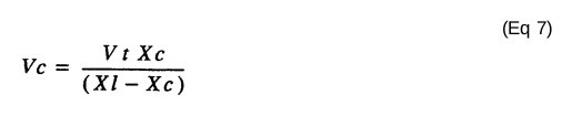](https://stanslegacy.com/uploads/images/gallery/2023-12/o65BVW3T4uncBvSv-image-1703202477600.png) During resonant interaction, the **incoming unipolar pulse train** (64a xxx 64n) of Figure (320) as to Figure (3-21) produces a **step charging voltage effect** across **excitor-array** (66/67) (57) as so illustrated in Figure (3-21).| Figure (3-21) [](https://stanslegacy.com/uploads/images/gallery/2023-12/qZcJcpsQWujxY3uB-image-1703202650133.png) |
**Voltage intensity** increases from **zero** "**ground-state**" to a **high positive voltage potential** in an progressive function.
Once **voltage-pulse** (64) is terminated or switch-off, **voltage potential** returns to "**ground-state**" (61) or near ground-state *(**diode** 55 maintains voltage charged across capacitor 57)* to start the voltage deflection process over again as pulse train (64a xxx 64n) continues to be duplicated.
"Voltage intensity or level across **excitor array** (57) can *exceed 20,000 volts* due to **circuit** (60) interaction and is directly related to **pulse train** (64a xxx 64n) **variable amplitude** input.
**Inductor** (56) is made of or composed of **resistive wire** to further restrict D.C. current flow beyond **inductance reaction** (Xl), and, is given by (Eq 8) [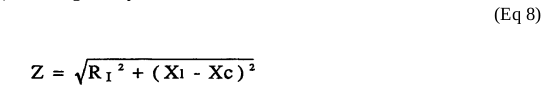](https://stanslegacy.com/uploads/images/gallery/2023-12/d2Puqn7VvWKdh4XB-image-1703202206972.png) **[](https://stanslegacy.com/uploads/images/gallery/2023-12/K7QoIRjYjGqOS8C3-image-1703201617139.png)Variable inductor-coil** (62) of Figure (3-22), similar to **inductor** (56) connected to **opposite polarity voltage zone** (67) further inhibits electron movement or **deflection** within **voltage intensifier circuit** (60).**Movable wiper arm** (73) of Figure (3-22) fine "tunes" "**resonant action**" during pulsing operations.
**Inductor** (62) in relationship to **inductor** (56) electrically balances the **opposite electrical potential** across **voltage zone (**66/67).
Since **pickup coil** (52) is also composed of or made of **resistive wire-coil**, then, **total circuit resistance** is given by (Eq 9)
[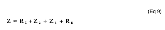](https://stanslegacy.com/uploads/images/gallery/2023-12/Ckks49Ih0Dt6GhuX-image-1703201978946.png)where, RE is the **dielectric constant** of natural water.
Ohm's law as to **applied electrical power**, which is (Eq 10)
[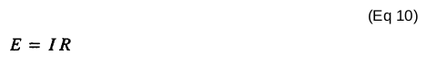](https://stanslegacy.com/uploads/images/gallery/2023-12/1AudiDYWkp7BubDT-image-1703201955646.png) where, (Eq 11) [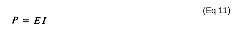](https://stanslegacy.com/uploads/images/gallery/2023-12/lLpTWNFW6aGZp7eV-image-1703201934685.png) Whereby,**electrical power** (P) is an linear relationship between two variables, **voltage** (E) and **amps** (I).
[](https://stanslegacy.com/uploads/images/gallery/2023-12/Tus1Xr1U62DJCsDx-image-1703201534713.png)Amp restriction *beyond* "**resonant action**" occurs when **unipolar magnetic field coupling** (71) of Figure (3-23) is allowed to simultaneously drop (*pulsating magnetic field*) across **both** **resonant charging chokes** (56/62) during pulsing operations since **electron mass** is an **electromagnetic entity** which is **subject to inductor fields** (56/62) produced by **pulsating magnetic field** (71a xxx 71n) of Figure (3-23).**Amp leakage** (*electron coupling to water*) **to water bath** (68) of Figure (3-24) is further prevented by encapsulating **resonant cavity** (57) in **delrin material** (72) of Figure (3-25) which is an electrical insulator to high voltage.
| Figure (3-24) [](https://stanslegacy.com/uploads/images/gallery/2023-12/1WXhsCSuTnngaFfo-image-1703197217269.png) | Figure (3-25) [](https://stanslegacy.com/uploads/images/gallery/2023-12/jmc1Z2WkjHNbWiZ6-image-1703201429384.png) |
**Delrin material** (72) **insulator value** remains intact since insulation material (72) is resilient to water absorption.
Inherently, then, **pulsing core** (53) of Figure (3-23) aids amp restriction while **voltage intensifier circuit** (190) is being "**tuned**" (*adjusting pulse train 49a xxx 49n pulse-frequency 63 via pulse frequency generator 70 of figure 3-5*) to match the resonant frequency properties of **water bath** (68) of Figure (3-22), as illustrated in **Fuel Cell** (120) of Figure (3-24).| Figure (3-22) [](https://stanslegacy.com/uploads/images/gallery/2023-12/K7QoIRjYjGqOS8C3-image-1703201617139.png) | Figure (3-23) [](https://stanslegacy.com/uploads/images/gallery/2023-12/Tus1Xr1U62DJCsDx-image-1703201534713.png) |
| Figure (3-22) [](https://stanslegacy.com/uploads/images/gallery/2023-12/K7QoIRjYjGqOS8C3-image-1703201617139.png) | Figure (3-27) [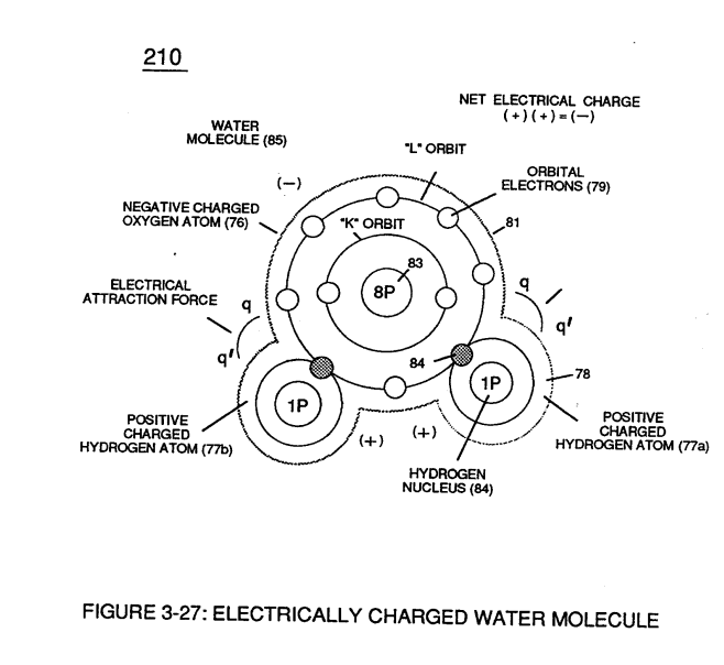](https://stanslegacy.com/uploads/images/gallery/2023-12/X69aZJeEKE3sC7yr-image-1703201640663.png) |