# Water Fuel Injection System - Page 2
To ensure proper energy-flame projection and subsequent energy-flame stability, **constant displacement** **water pump** (170) causes and allows **ionized ambient air gases** (46), **noncombustible gases** (45), and **water** (47) to be displaced under static pressure up to and beyond 125 lbs psi, respectively.
**[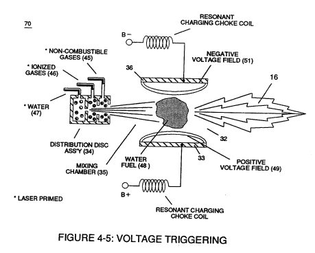](https://stanslegacy.com/uploads/images/gallery/2023-12/uX9zLfvLDlmTuhBw-image-1703044341327.png)Energy-Flame** density is enhanced and sustained by causing **ionized gases** (46a xxx 46n) of **spray port** (42) to be deflected into **liquid spray path** (41), together **water mist** (47) and **ionized air gas** (46) are, now, directed toward and deflected through non-combustible **gas spray path** (43)
... producing uniformed **water-fuel mixture** (48), as illustrated in Figure (4-5).
**Energy-Flame** temperature is regulated by controlling the volume flow-rate of each **fluid-mediums** (47 / 45 / 46) in direct relationship to **applied voltage intensity** (33 / 36), as further illustrated in Figure (4-2) as to Figure (4-5).
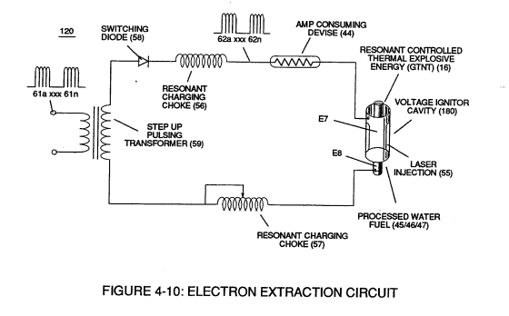
To elevate **Energy-flame-temperature** still further, simply increase **fluid-displacement** (46/47) while maintaining or reducing the volume flow rate of **non-combustible gases** (45) during an increase of **applied voltage amplitude** (V0 xxx Vo) of Figure (4-2) as to **Voltage Intensifier Circuit** (110) of Figure (4-9) and **Electron Extraction Circuit** (120) of Figure (4-10).
To lower **Energy-flame** temperature simply increase the amount of **non-combustible gases** (45a xxx) or reduced the **fluid flow rate** (45 / 46 / 47) uniformly while lowering **pulse voltage amplitude** (xxx V0).
To establish a predetermined or given **Energy-flame** temperature adjust **fluid-medium** (45 / 46 / 47) and applied **voltage amplitude** (V0 xxx) independent of each other to obtain the desired results.
[](https://stanslegacy.com/uploads/images/gallery/2023-12/uX9zLfvLDlmTuhBw-image-1703044341327.png)The resultant **energy-flame** pattern is further maintained by allowing the ignited, compressed, and moving gases (29) of Figure (4-5) to be projected to, pass through and beyond **nozzle-port** (32) under pressure due to gas expansion caused by thermal gas ignition.
[](https://stanslegacy.com/uploads/images/gallery/2023-12/X6GbSuaxjtJ9yQyr-image-1703045172819.png)
**Voltage Igniter Stage** (180) of Figure (4-5) as to **Voltage Intensifier Circuit** (110) Figure (4-9) as to **Extraction Circuit** (10) of Figure (4-10) performs several functions simultaneously to initiate and trigger thermal explosive energy-yield (gtnt) (16) beyond normal gas burning levels:
**Water droplets** (28a xxx 28n) escaping from **spray-mist** (47) and exposed to high intensity voltage fields of opposite polarity 33/36) are stimulated to undergo **Electrical Polarization Process** (160) of Figure (3-26)
... which not only separates and splits the unlike atoms of the water molecule but also causes the unlike atoms (hydrogen atoms 77a /77b and oxygen atom 76) to experience **electron ejection** (230) of Figure (3-30) as to (71) of Figure (4-10) since **voltage intensifier circuit** (110) of Figure (4-9) inhibits and prevents electron flow to enter into **gas ignition process** (180), as further illustrated in Figure (4-8).