Author does not accept and liabilities/responsibilities for those individuals who chose to build the below cell. This information on this site is for educational purposes only.
Cavity shown on Chris Bake's YouTube channel: [10 Cell Tubular Resonant Cavity](https://stanslegacy.com/attachments/94)
Single cavity with entry/flow holes at bottom. Accepts 3/4" (19.05mm) and 1/2" (12.7mm) stainless steel tubes. Nuts recessed are sized for 10-32" stainless steel nuts, and 10-32" stainless steel (18-8) set screws. Top accepts 1/2" long 10-32 set screws, bottom accepts 5/8" long 10-32 set screws. Holes are sized for 10-32 tap to thread if desired. 3D filament is regular PLA. Should only need 1 spool of filament, as all prints were done at 50% infill.
Supplier Site: [10-32 SS Nuts](https://stanslegacy.com/attachments/69) , [1/2" 10-32 SS set screw](https://stanslegacy.com/attachments/70) , [5/ 10-32 SS set screw](https://stanslegacy.com/attachments/71) , [1/2" OD, 0.065" Wall, 0.375" T-304 SS Tube](https://stanslegacy.com/attachments/72) , [3/4", 0.035" wall, 0.68" ID T-304 SS Tube](https://stanslegacy.com/attachments/85) , [T-304 SS connecting wire](https://stanslegacy.com/attachments/86) , [PLA White 1Kg Spool](https://stanslegacy.com/attachments/87)
[hex resonant cavity with flow holes .stl](https://stanslegacy.com/attachments/68) [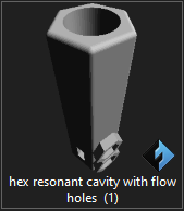](https://stanslegacy.com/uploads/images/gallery/2022-10/FgVmE4XrKZZQeDMI-image-1667233965315.png)Base plate that accepts 10 of the single resonant cavities above. The cavities outer body will need to be filed a little to provide press fit into the below plate. Holes on the outer edge are for 6-32" tap if so desired to prevent resonant cavity from coming out if loose fitting happens.
[WFC base plate v1 v0.stl](https://stanslegacy.com/attachments/74) [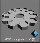](https://stanslegacy.com/uploads/images/gallery/2022-10/ZZbO7Ukfmjiq52DL-image-1667233980842.png) Depending on the vessel diameter used, the base plate may need to be reduced in OD. I accomplished this with a bench grinder and sandpaper. Needle nose pliers are helpful in tightening connections. A 10-32 tap was run through holes that set screws go into. Connect two in series at a time for easier construction/wiring. The OD diameter of the base was intended for the 5.75" ID acrylic tube I used. However, any clear vessel or bucket can be used for testing. Nothing specific for the base being 5.75" OD. The 3/4" SS tubing needs cut to a length of 3.00" 10 qty total needed (total length of 30.00" minus blade width for 10 cuts, approximately 5/8", need 31" total)As of 12/01/2022 above supplier has 36" length for $21.71
The 1/2" SS tubing needs cut to a length of 3.50" 10 qty total needed ( total length of 35.00" minus blade width for 10 cuts, approximately 5/8", to 36" total)As of 12/01/2022 above supplier has 36" length for $37.34
Many methods for cutting can be used, whichever is available to the builder.As of 12/01/2022, PLA filament is $20.00
20 qty, 10-32 SS nuts ($0.08/ea)= $1.60
10 qty, 10-32 x 1/2" SS set screws ($0.17/ea) = $1.70
10 qty, 10-32 x 5/8" SS set screws ($0.20/ea) = $2.00
As of 12/01/2022 above supplier has SS wire for $7.99
With the itemized list above, the cost to print/assemble this cell is approximately: $92.34
# Variable Pulse Frequency Generator (K2) Component Interface PlatePlate for mounting 4 rotary switches (3/8" diameter threads), 1 precision 10-turn potentiometer (3/8" diameter threads), and 1 5mm LED.
[Variable Pulse Freq Gen Component front plate v3.stl](https://stanslegacy.com/attachments/75) [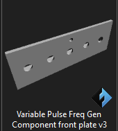](https://stanslegacy.com/uploads/images/gallery/2022-10/nObSV8maKaQkOFSg-image-1667234047538.png) # VIC 5 coil [meyer\_bobbin\_ends.stl](https://stanslegacy.com/attachments/76) [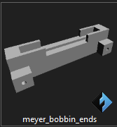](https://stanslegacy.com/uploads/images/gallery/2022-10/b5tX4SVHTNlqn7Jw-image-1667234172378.png) # Coil Winder For VIC5End cap for holding VIC5 bobbin. Bottom has hexagonal recess for 5/16" nylon lock nut. Best method is to lay flat, line up nut flat edges and lightly tap with hammer flush into recess. This avoids glue being needed.
[VIC5 winder end caps .stl](https://stanslegacy.com/attachments/84) [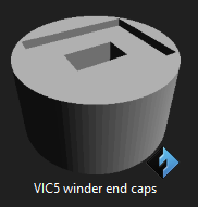](https://stanslegacy.com/uploads/images/gallery/2022-12/dvHlaD9yyNGOonSh-image-1669865145881.png) # Hydrogen Gas Gun - 3D STLsAs of 5-2-23, the below STLs are currently being printed and tested. It is recommended until verification of the parts is completed, that the content herein should be for information only.
Estate photographs were used in conjunction with a pair of calipers. Screen was adjusted until a common reference point was ascertained. The reference point used was the known dimensions of the LED PCB width, being 1.00". Length was determined by laying out the number of 5mm LEDs (16-qty) in a PCB CAD software. The distance from the first to the last was exactly 4.00". When the screw terminal via holes are added, the board length becomes 4.75" long. This is what decided the length of the acrylic body. [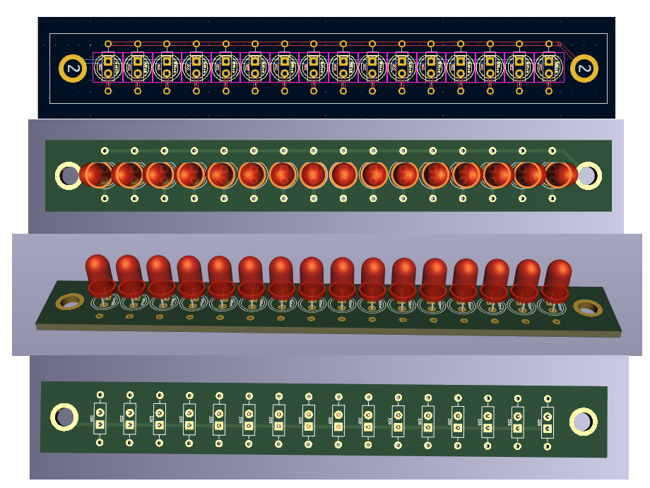](https://stanslegacy.com/uploads/images/gallery/2023-05/5hO4cEjYSEvp94ae-image-1683112814433.png) ##### **ACRYLIC PHOTON INJECTION BODY:** [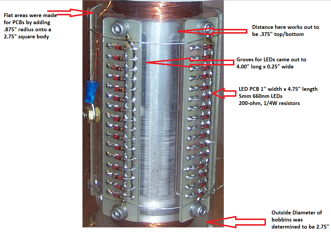](https://stanslegacy.com/uploads/images/gallery/2023-05/dt6CnFme4dbtURi3-image-1683114156367.png) Acrylic "photon injection" diameter: 2.75" (note that flat spots were intentionally done on the 3D prints to allow for LED PCBs. It was found that a square of equal sides, 2.75" with .875" radius on each corner produced the desired outer diameter and provided 1" wide flat surfaces for PCB mounting). A 0.375" depth was chosen based off dimensions of 5mm LEDs for the grooved portion. **ACRYLIC BOBBINS:** Top and bottom bobbin end appear to have some type of mounting holes that appear to line up with holes on the end caps. These were determined to the closest approximate of 2.125" on centers. This was included in STL designs. [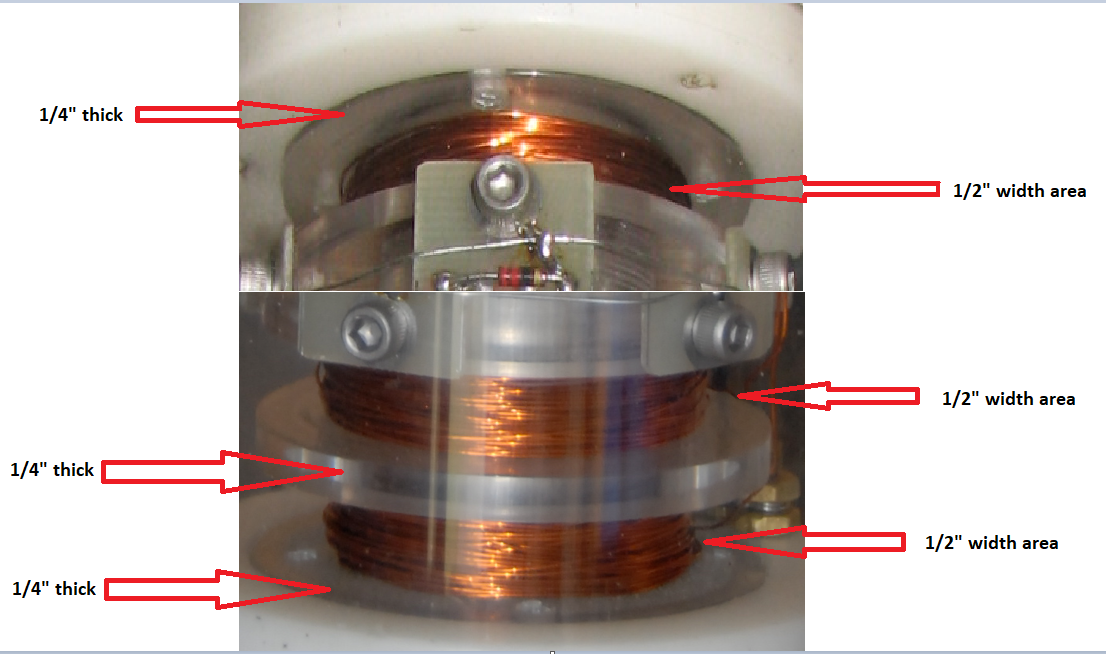](https://stanslegacy.com/uploads/images/gallery/2023-05/t9JMxcSec2cpN8lw-image-1683114551899.png) ##### **REPLICATION BREAKDOWN:** The photo injection body is meant to be printed in PLA/PETG as this shouldn't be required to be clear, as only in inner chamber has light pulsed. There are two pieces. One top and one bottom. There was intentionally a shorter section on the bottom (1a) and a longer section on the top (1b). This is functioning as a keying to avoid mistakes in assembly. These two section need to be glued at their center junction. The larger diameter seen is for a acrylic resin cast from a mast mold. [HGG Body Bottom Half.stl](https://stanslegacy.com/attachments/153) [HGG Body Top Half.stl](https://stanslegacy.com/attachments/154) [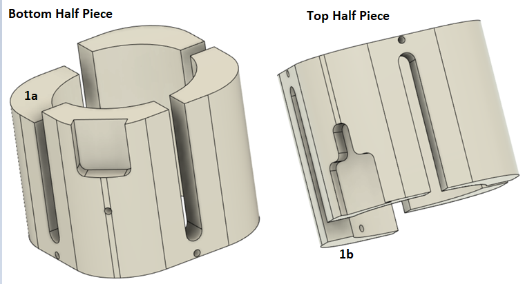](https://stanslegacy.com/uploads/images/gallery/2023-05/hKCsJOFo4zX53Zny-image-1683133833626.png) [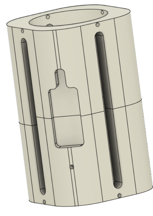](https://stanslegacy.com/uploads/images/gallery/2023-05/rRSw81rz5WNjzM6s-image-1683134547215.png) ##### **ACRYLIC LENS:** Having solid piece of acrylic machined is costly and difficult to source for only one piece. These hurdles inspired the idea of 3D printing a mold template. There is a hole provided for tapping a 10-32 screw connection into outer electrode. Once cured, the lens is inserted coaxially to the inner/outer electrode. For best results, the silicone mold and acrylic resin should be placed inside vacuum chamber to remove air bubbles during curing. Gluing is not intended for this piece. Inner Diameter: 1.025" Outer Diameter: 1.980" Length is 4.50" [Acrylic Lens Mold Piece.stl](https://stanslegacy.com/attachments/128) [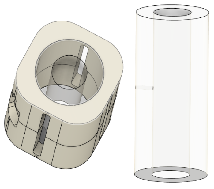](https://stanslegacy.com/uploads/images/gallery/2023-05/TN8q8Bc0LFc1nTSm-image-1683136809693.png) ##### **PHOTON BODY END PLATES:** In order to secure the acrylic lens, and provide a gluing surface for coil bobbins, two "end caps" are to be glued into place on each end of the body. This brings the total length to 4.75". [HGG .065\_ Body Ends.stl](https://stanslegacy.com/attachments/152) [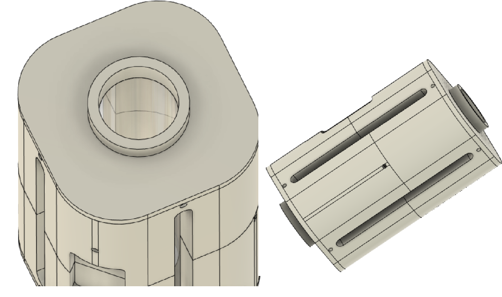](https://stanslegacy.com/uploads/images/gallery/2023-05/z8yXetay6eWkLmmu-image-1683137340118.png) ##### **OUTER ELECTRODE:** Outer electrode is T-304 stainless steel tube. 7.00" in length, 1.00" outside diameter, 0.94" inside diameter, 0.030" wall. Grooves are cut at 90 degree displacements, measuring 4.00" long. [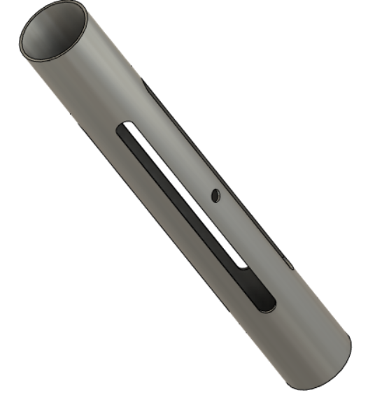](https://stanslegacy.com/uploads/images/gallery/2023-05/7TcjYMjoswHkTs2P-image-1683137730695.png) ##### **OUTER ELECTRODE STENCIL:** Being that the machining required to cut grooves in the tubing is costly, for only one piece, an stencil to go over the body for marking grooves was made. The intention was to cut the grooves with Dremel cutting wheel. [LED Groove Bottom.stl](https://stanslegacy.com/attachments/155) [LED Groove Top.stl](https://stanslegacy.com/attachments/156) ##### **INNER ELECTRODE:** [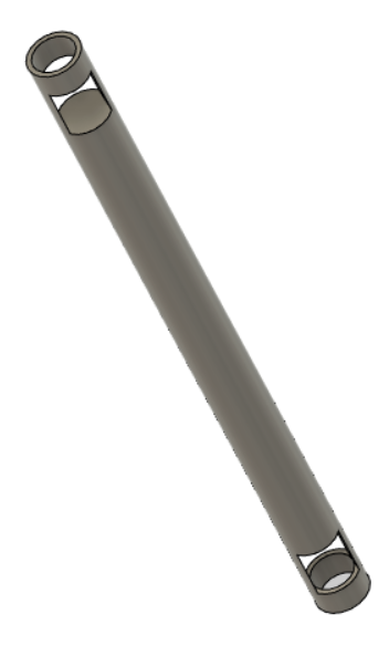](https://stanslegacy.com/uploads/images/gallery/2023-05/kcl6beSiVBpkUhwp-image-1683137995144.png) ##### **BODY TOP END BOBBIN HALF PIECE:** Glue the 0.25" thick bobbin to the top via the 1.30" surface. This will complete the top bobbin for coil. [HGG bobbin half piece .25 thick.stl](https://stanslegacy.com/attachments/129) [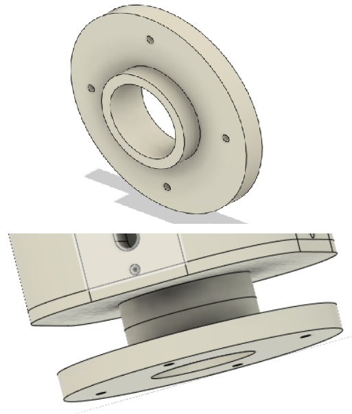](https://stanslegacy.com/uploads/images/gallery/2023-05/Q5N18wmFlUQYSe3p-image-1683138359258.png) ##### **BODY BOTTOM BOBBIN HALF PIECE:** At the bottom of the body, glue a .125" thick bobbin half piece to the corresponding 1.30" diameter surface. [HGG Bobbin half piece .125 thick.stl](https://stanslegacy.com/attachments/130) [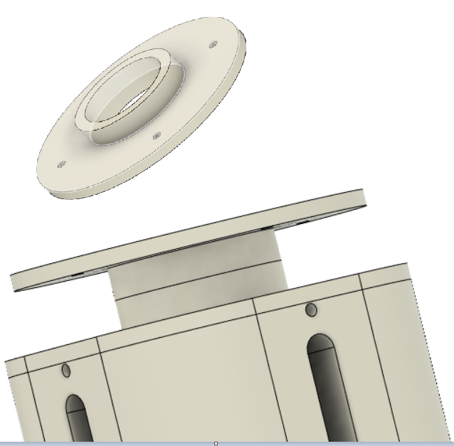](https://stanslegacy.com/uploads/images/gallery/2023-05/cMSiZvM4EFLYAPX5-image-1683138713688.png) Next, glue another .125" thick bobbin half piece to the 2.75" surface. [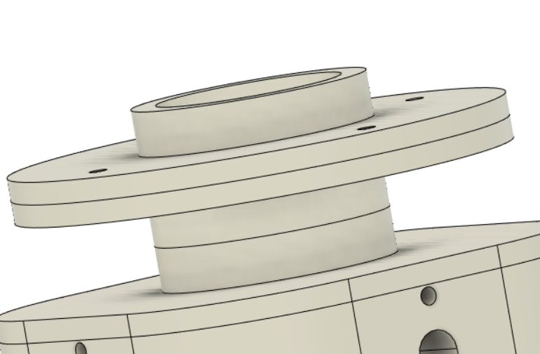](https://stanslegacy.com/uploads/images/gallery/2023-05/ITGT0MfV8D4LfgRo-image-1683138832988.png) Next, glue last .25" bobbin half piece the 1.30" surface. [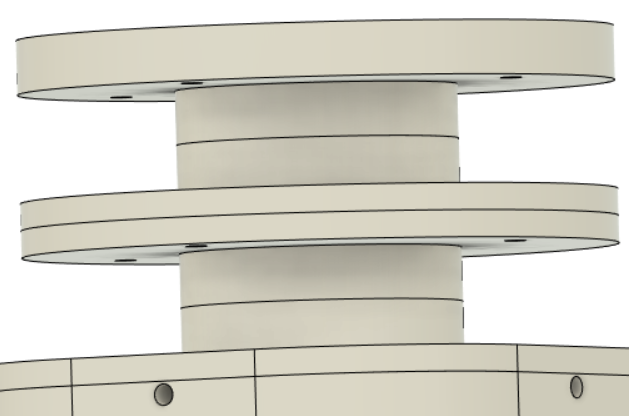](https://stanslegacy.com/uploads/images/gallery/2023-05/iUs2fYMx1ui1OR05-image-1683138915613.png) ##### **COMPLETE ASSEMBLY:** Following the steps above will yield a completed assembly. [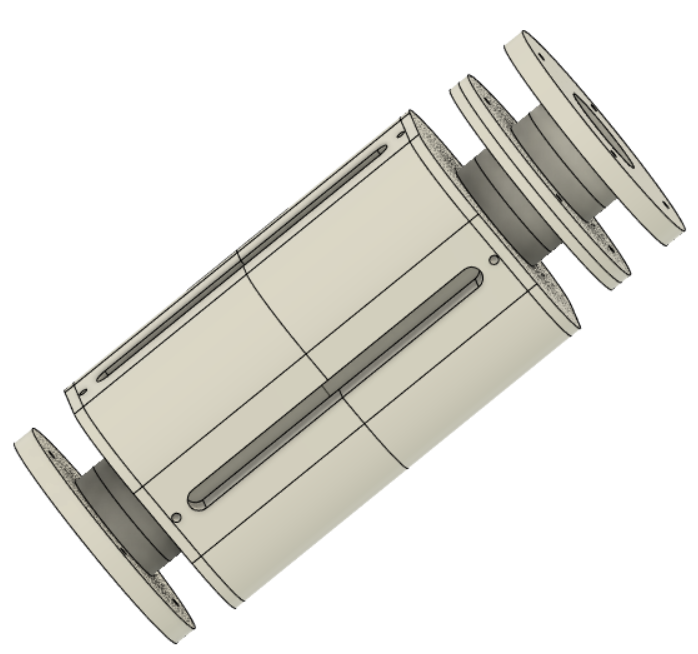](https://stanslegacy.com/uploads/images/gallery/2023-05/RYhKgsxXgOA2txbd-image-1683138960688.png) ##### **INSERT OUTER ELECTRODE:** Press fit in the 1" outer electrode, aligning the grooves in the tube with the grooves in the plastic body. [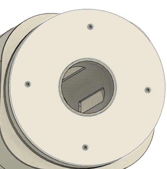](https://stanslegacy.com/uploads/images/gallery/2023-05/nwbs8r4k22RhVX9d-image-1683139818187.png) ##### **BOTTOM END CAP:** The bottom end cap has recessions on the bottom to receive wiring. Terminals are 8-32" brass screws. Inner electrode should be press fitted like shown. [Bottom End Cap.stl](https://stanslegacy.com/attachments/148) [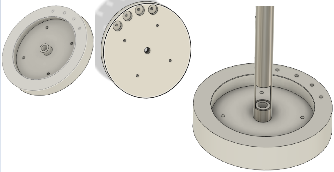](https://stanslegacy.com/uploads/images/gallery/2023-05/mGKOLvjaBtLscvBO-image-1683140505338.png) Insert the inner electrode so it is coaxial to the inside of the outer electrode. [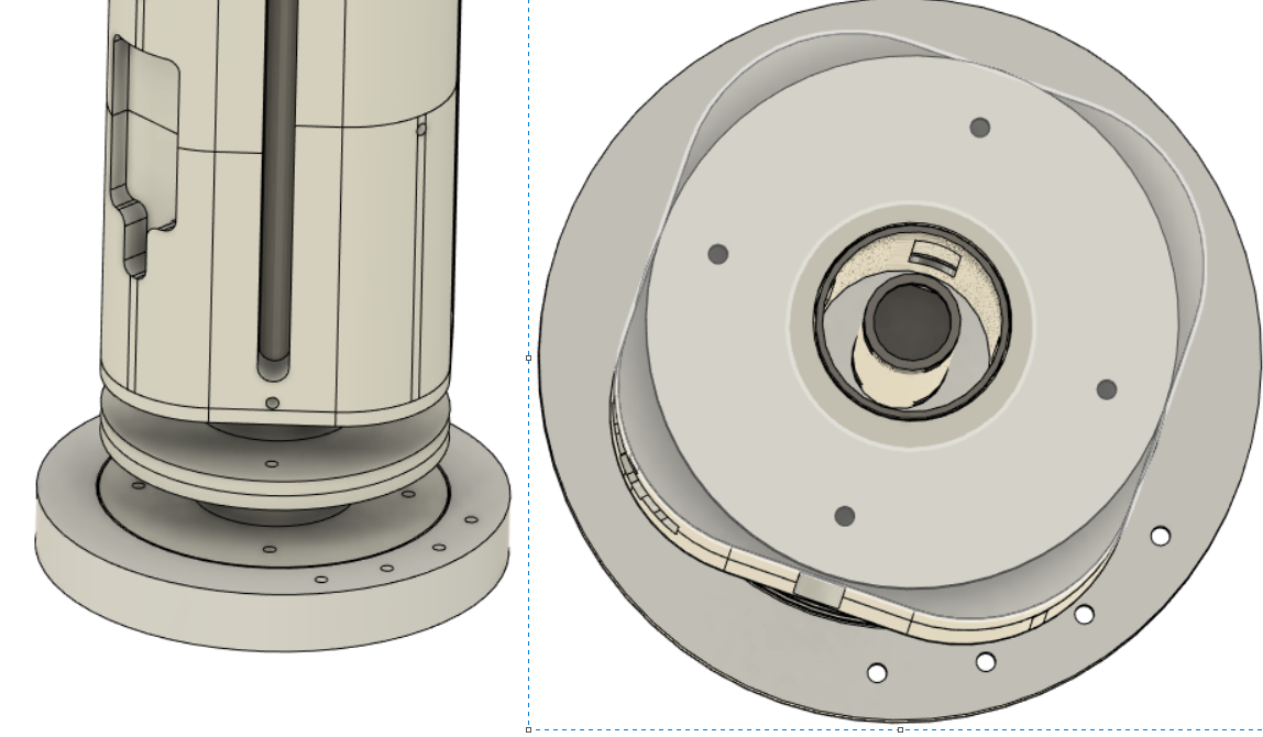](https://stanslegacy.com/uploads/images/gallery/2023-05/p89aCJJHwatWS9uV-image-1683140731878.png) ##### **TOP END CAP:** Repeat the same step for top end cap that was done for the bottom be inserting inner electrode into middle support. [Top End Cap.stl](https://stanslegacy.com/attachments/147) [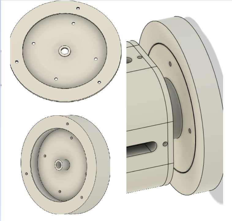](https://stanslegacy.com/uploads/images/gallery/2023-05/nKgfIUy64i4QThBj-image-1683141261497.png) ##### **INSTALLING TOP/BOTTOM CAPS:** Top cap goes on top of the "top end cap". [HGG Top Cap.stl](https://stanslegacy.com/attachments/145) [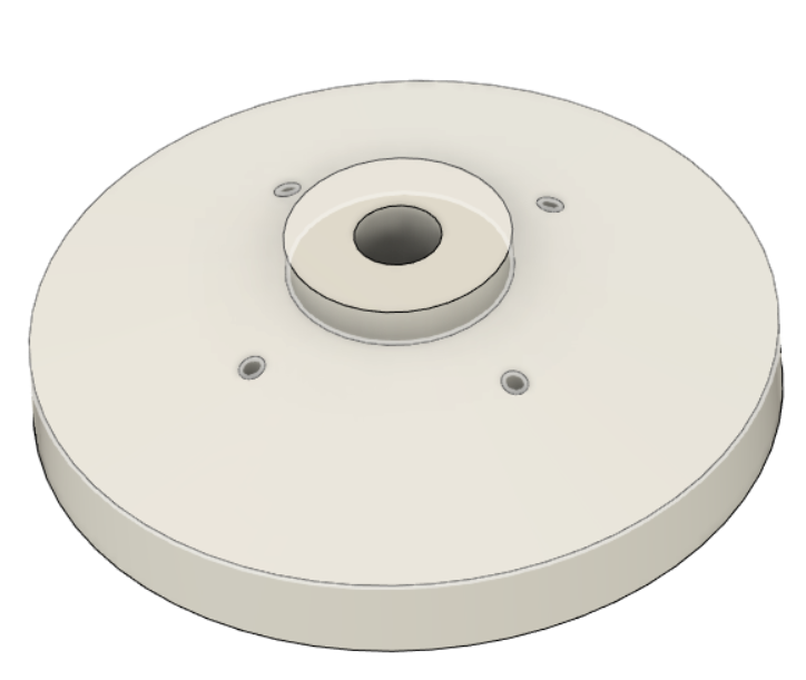](https://stanslegacy.com/uploads/images/gallery/2023-05/8rNZWmLMBJJ7Aq3W-image-1683147505745.png) Bottom cap goes onto the bottom end cap. 2.125" holes line up for securing through "bottom end cap" and bottom 0.25" wall coil bobbin. When installing this one, make sure the four holes on the side match the four holes on the inside. [HGG Bottom Cap.stl](https://stanslegacy.com/attachments/146) [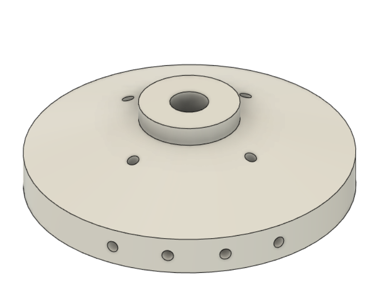](https://stanslegacy.com/uploads/images/gallery/2023-05/f6Ep7RWN1KDtJqAN-image-1683147623703.png) ##### **COMPLETE UNIT:** This is what the entire unit should look like once completed. [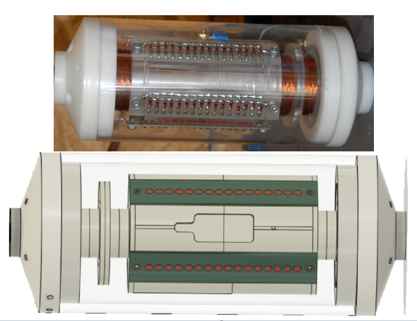](https://stanslegacy.com/uploads/images/gallery/2023-05/nYhTdJu869nwtNaA-image-1683147984723.png) ##### **ORIGINAL HYDROGEN GAS GUN:** [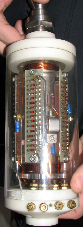](https://stanslegacy.com/uploads/images/gallery/2023-05/gLpHs9iVg7iLBOev-image-1683148133440.png) # Gas Processor - 3D STLsAs of 5-18-23, STLs are being printed to test assembly. At this time, until this banner is removed, please do not attempt printing. Verification is needed before others waste time and resources for parts that don't go together. Thank you.
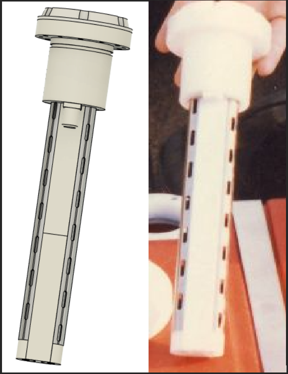
##### **RETAINING CAP:** (100% Fill: 65G) , (50% Fill: 45G) [Retaining Cap.stl](https://stanslegacy.com/attachments/164) [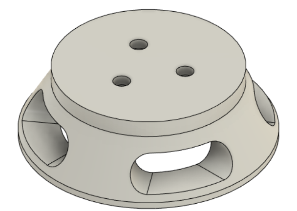](https://stanslegacy.com/uploads/images/gallery/2023-05/xn02dVCL1c4EAxh4-image-1684418669595.png) ##### ##### **UPPER INTAKE:** (100% Fill: 29G) , (50% Fill: 23G) [Upper Intake.stl](https://stanslegacy.com/attachments/165) [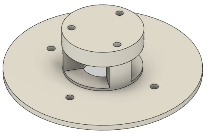](https://stanslegacy.com/uploads/images/gallery/2023-05/83dqmpQsvTAKlHQf-image-1684419208483.png) ##### **BOTTOM PIECE OF UPPER INTAKE:** (100% Fill: 2G) , (50% Fill: 2G) [Bottom Piece To Upper Intake.stl](https://stanslegacy.com/attachments/158) [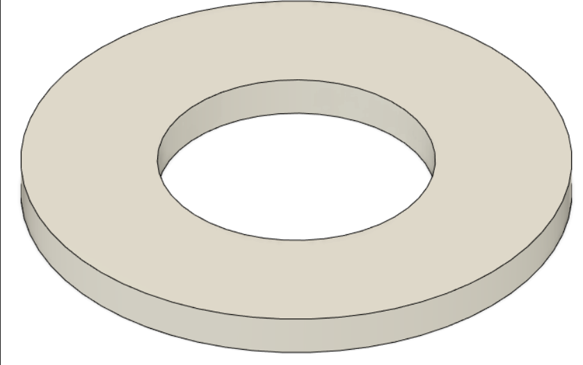](https://stanslegacy.com/uploads/images/gallery/2023-05/fUam7aH745qq8t67-image-1684419239051.png) ##### **TOP O-RING** (100% Fill: 44G) , (50% Fill: 29G) [Top O-Ring Plate.stl](https://stanslegacy.com/attachments/159) [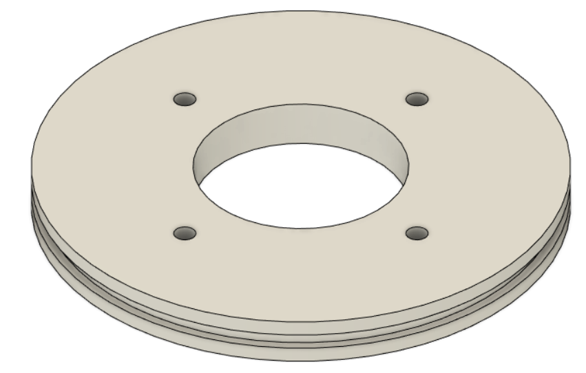](https://stanslegacy.com/uploads/images/gallery/2023-05/IUGKvl4uW1Fi8sR4-image-1684419288435.png) ##### **LED BODY:** (100% Fill: 206G) , (50% Fill: 120G) [LED Body.stl](https://stanslegacy.com/attachments/161) [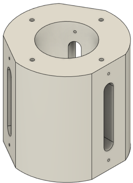](https://stanslegacy.com/uploads/images/gallery/2023-05/6QfFa1zPZESddmwN-image-1684419313028.png) ##### **OPTICAL LENS:** (100% Fill: 58G) , (50% Fill: 37G) [Optical Lens.stl](https://stanslegacy.com/attachments/163) [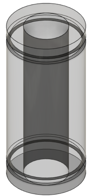](https://stanslegacy.com/uploads/images/gallery/2023-05/rQYrlKyeLSW1z4PH-image-1684419366500.png) ##### **OUTER** **ELECTRODE DIMENSIONS:** ##### **OUTER ELECTRODE LED GROOVE STENCIL:** (100% Fill: 6G) , (50% Fill: 6G) [Outer Electrode Stencil .stl](https://stanslegacy.com/attachments/160) [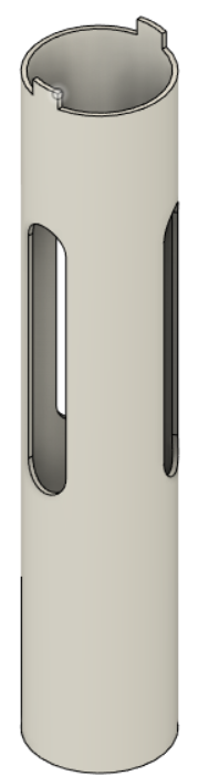](https://stanslegacy.com/uploads/images/gallery/2023-05/nfPGQr3evEYkLG9S-image-1684419404720.png) ##### **INNER ELECTRODE DIMENSIONS:** ##### **BOTTOM O-RING & BLOCK PLATE:** (100% Fill: 68G) , (50% Fill: 43G) [Bottom O-Ring & Block Plate.stl](https://stanslegacy.com/attachments/167) [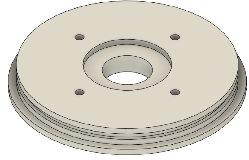](https://stanslegacy.com/uploads/images/gallery/2023-05/dBMXs6ocA7ao16IP-image-1684419429550.png) ##### **BOTTOM BLOCK:** (100% Fill: 265G) , (50% Fill: 152G) [Bottom Block.stl](https://stanslegacy.com/attachments/166) [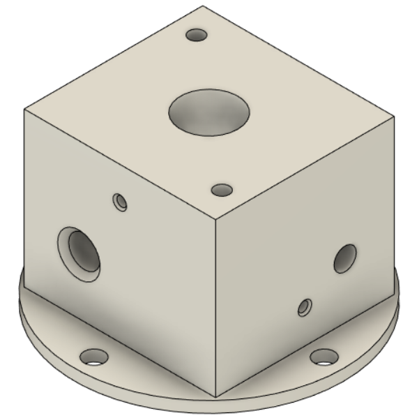](https://stanslegacy.com/uploads/images/gallery/2023-05/zDTgfs1SfHpfQZKN-image-1684419457544.png) ##### **LED COVER:** (100% Fill: 90G) , (50% Fill: 71G) [LED Cover.stl](https://stanslegacy.com/attachments/162) [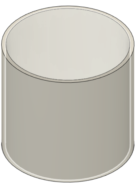](https://stanslegacy.com/uploads/images/gallery/2023-05/jytV43XDQKuHr31p-image-1684419483003.png) ##### **TOTAL ASSEMBLY:** [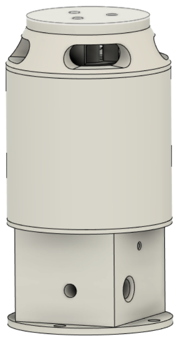](https://stanslegacy.com/uploads/images/gallery/2023-05/Ru8DGkR8lCdxZ62V-image-1684419543522.png) # Photon Injected Resonant Cavity - 3D STLs Stan had a "triple stack" which was composed of three individual resonant cavities stacked on top one another. These were large and made of machined Delrin. At the top of each was a circular PCB composed of 5mm 660nm LEDs. 660nm LEDs were seen throughout Meyer's technology. In an effort to miniaturize, and ease investigations for such, I have designed a version that uses the tube dimensions of the small resonant cavities. ##### **FINISHED ASSEMBLY:** Body of the unit. Received 4 LED PCBs at a 90 degree displacement around the periphery. Internal has an acrylic "lens", 0.75" outer electrode, and 0.50" inner electrode coaxially placed relative to one another. Two 1/4" holes are 180 degrees displaced relative to one another for mounting via nylon all thread rod. Hole for connections to the internal tubes are provided (on seen here for 0.75") on the side. Also, using a new method, at the bottom of the body for the inner electrode (see at bottom). [Photon Injected Resonant Cavity Body.stl](https://stanslegacy.com/attachments/151) [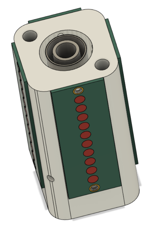](https://stanslegacy.com/uploads/images/gallery/2023-05/0e1pcv5g6mopso3Y-image-1683129828547.png) ##### **INNER ELECTRODE:** 1/2" (0.500") outside diameter. 3.50" long. T-304 stainless steel tube. 0.060" wall. [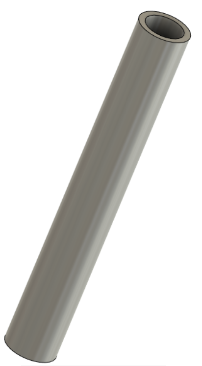](https://stanslegacy.com/uploads/images/gallery/2023-05/O0k3C07barNJhTmR-image-1683132423329.png) ##### **OUTER ELECTRODE:** 3/4" (0.75") outside diameter. 3.00" long. T-304 stainless steel. 0.035" wall. Machining these slots can become pricey. Therefor, a stencil that slides over the electrode can be used to manually mark the area for the grooves and cut them out in an alternative fashion. [Tube LED Groove Stencil.stl](https://stanslegacy.com/attachments/149) [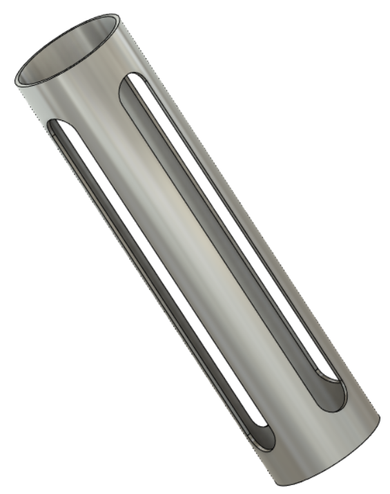](https://stanslegacy.com/uploads/images/gallery/2023-05/lhULktGYPuYZggwe-image-1683132512340.png) ##### **ACRYLIC LENS:** Acrylic lens is made from casting resin. This below would be finished product. Included is the hole for connecting to 3/4" electrode from outside. STL would be template for making a master mold. [Acrylic Lens For Mold.stl](https://stanslegacy.com/attachments/150) [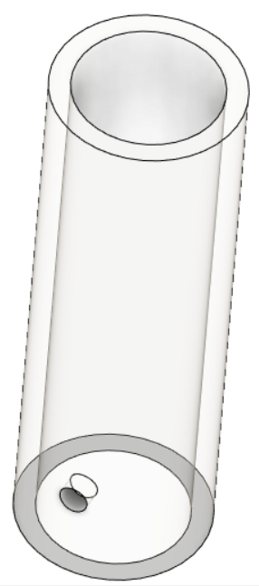](https://stanslegacy.com/uploads/images/gallery/2023-05/eN7okK754gHYm8JO-image-1683132610658.png) ##### **LED PCB:** Representation of a PCB manufactured. Composed of 10 660nm - 5mm LEDs. [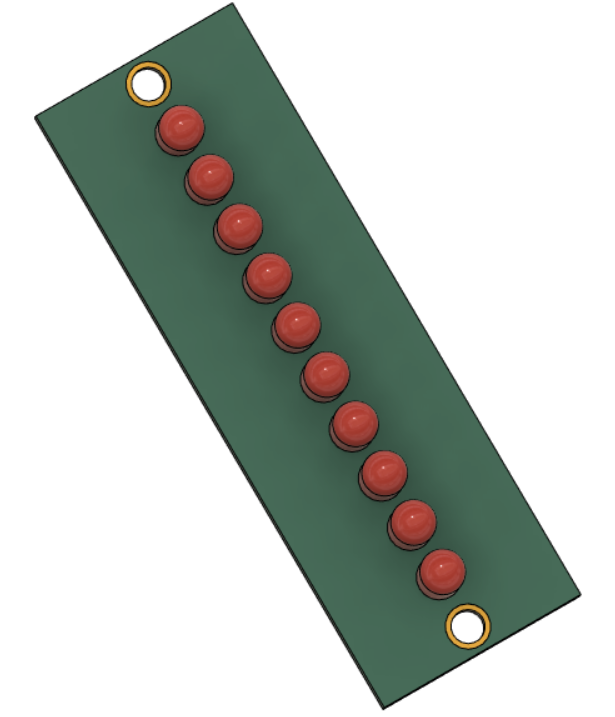](https://stanslegacy.com/uploads/images/gallery/2023-05/qyqHCSK1OyAV041w-image-1683132648744.png) ##### **TOP VIEW:** [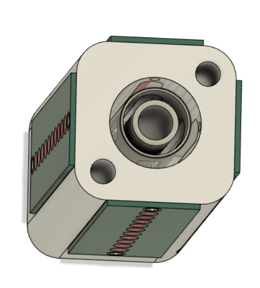](https://stanslegacy.com/uploads/images/gallery/2023-05/o7l1gRjKtS2K90A3-image-1683132261549.png) # Steam Resonator - 3D STLsAs of 5-3-23 the STLs shown in here are being printed to build a plastic model. At this point, please only consider the following as informational and do not print until all parts are verified to be correct.
[](https://stanslegacy.com/uploads/images/gallery/2023-05/0SBdYEyLocLaZlwo-image-1683164414839.png) ##### **TOP CAP:** Top cap is as the name implies. Screw holes are located around the periphery for mounting inside a water tank. Two holes for electrical connections can be seen near the center. [Steam Resonator Top Cap.stl](https://stanslegacy.com/attachments/135) [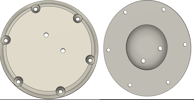](https://stanslegacy.com/uploads/images/gallery/2023-05/hPH6glNoES3WZWq6-image-1683161472325.png) ##### **ORING:** This piece is to be glued to the top cap to accept a sealing O-ring. The STL is for two half pieces that need to be glued together. [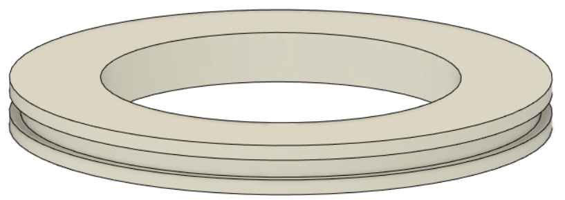](https://stanslegacy.com/uploads/images/gallery/2023-05/b2WpoTfO9qI1q3En-image-1683161501952.png) ##### **S/R MOUNT BASE:** The S/R block is the area that the coaxial orientated electrodes are recession into. This allows electrical connection at the top. [Steam Resonator SR Mount Base.stl](https://stanslegacy.com/attachments/136) [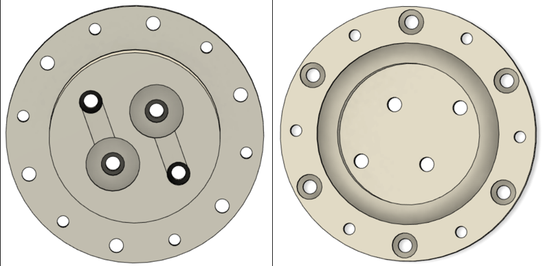](https://stanslegacy.com/uploads/images/gallery/2023-05/NAIIIdmpStmxFHhV-image-1683161258014.png) ##### **OUTER ELECTRODE:** Outer electrode is T-304 stainless steel tube. 0.625" outside diameter. 0.049" wall. 0.527" inside diameter. 7.725" long. Since machining slots could be difficult and costly, a stencil was made (two half pieces for easier printing) that slides over a .625" diameter tube for marking and manual machining. Stencil STLs are listed below. Stencil: [RESONATOR MILLING STENCIL TOP SECTION.stl](https://stanslegacy.com/attachments/140) , [RESONATOR MILLING STENCIL BOTTOM SECTION.stl](https://stanslegacy.com/attachments/139) [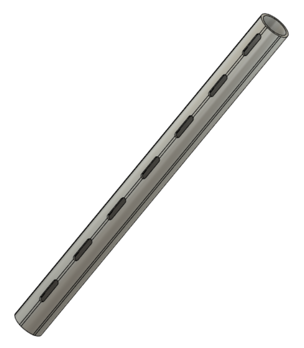](https://stanslegacy.com/uploads/images/gallery/2023-05/fNo2gH6zEnxZ2hBa-image-1683164451008.png) ##### **INNER ELECTRODE:** The inner electrode is T-304 stainless steel material. 0.25" outside diameter. 9.165" long. Machining will need to be done per the drawings. [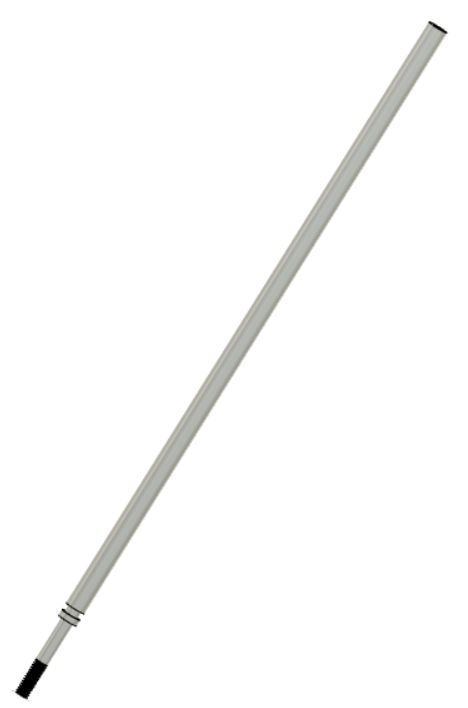](https://stanslegacy.com/uploads/images/gallery/2023-05/my4r1yKBdlpu11Iq-image-1683162046340.png) ##### **INSULATION BLOCK:** The insulative block is an insulation divide between the two outer electrodes. The overall length is 8.125". Square section is .150" tall. Given the length of the whole piece, STLs are half pieces that need glued together. [Insulative block 4.125\_ section .stl](https://stanslegacy.com/attachments/137) [Insulative block 4.00\_ section .stl](https://stanslegacy.com/attachments/138) [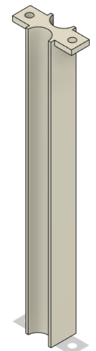](https://stanslegacy.com/uploads/images/gallery/2023-05/Xb8LxsaqLzCIlfHo-image-1683162228195.png) ##### **DELRIN NUT:** Delrin nut goes over the shorter threaded protrusion of the mounting pins through the insulative block [Steam Resonator Delrin Nut .stl](https://stanslegacy.com/attachments/143) ##### **MOUNT PIN:** ##### **END CAPS:** Delrin end caps that have a .300" recession for the inner electrode, and .100" protrusion for inserting into inner diameter of outer electrode. [END CAP REVISED .stl](https://stanslegacy.com/attachments/144) ##### **STEM PLATE:** ##### **ASSEMBLY:** **FIGURE 1:** Place the mounting pins into their respective recessions. The longer threaded portion goes up through the SR block. Shorter threaded ends go downwards through the insulative block's .150" square section. **FIGURE 2:** Insulative block is placed over the mounting pin's protrusions. [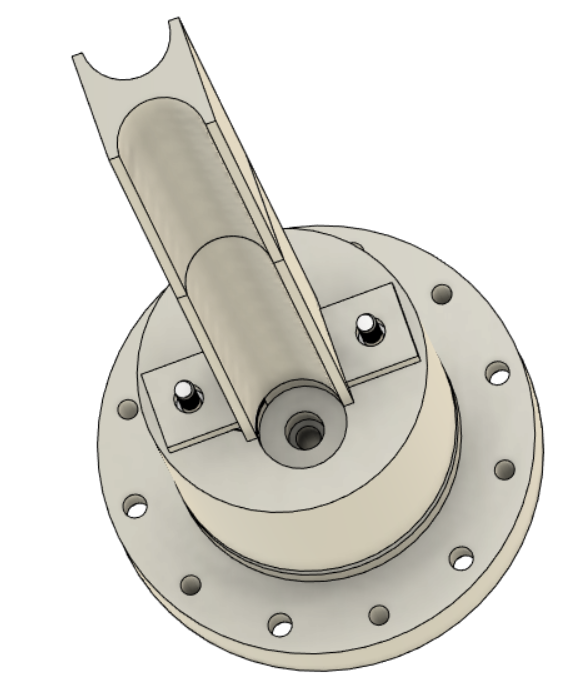](https://stanslegacy.com/uploads/images/gallery/2023-05/8X8RobtRktpMHKiS-image-1683163901973.png) **FIGURE 3:** Outer electrodes, with welded stem plates, are recessed into their corresponding holes (.200" recession into SR block). [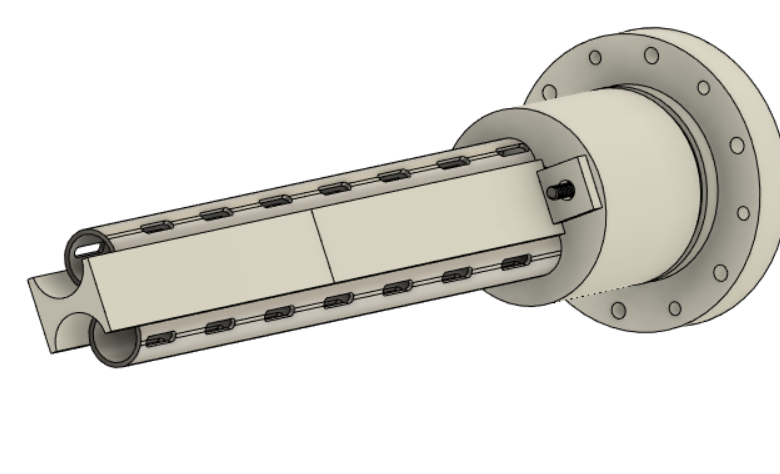](https://stanslegacy.com/uploads/images/gallery/2023-05/5G2DhAC6AZBXijpC-image-1683163947479.png) **FIGURE 4:** Place inner electrodes coaxially inside the outer electrodes. This is accomplished by recessing them into the SR block (.420" recession). [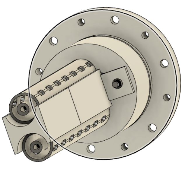](https://stanslegacy.com/uploads/images/gallery/2023-05/b0qugQ2tNqZaV6rc-image-1683164004577.png) **FIGURE 5:** End caps are placed onto the bottom. There is a .100" protrusion on the end caps that goes into the inner diameter of the .625" diameter tube. Through the bottom of these end caps, 6-32 stainless steel screws are secured. [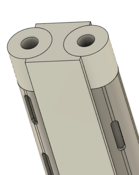](https://stanslegacy.com/uploads/images/gallery/2023-05/tuRdVlvsVfhb9PYp-image-1683163344758.png) **FIGURE 6:** Screw the delrin nuts (.500" outside diameter) onto the mounting pin threaded protrusions to secure the insulative block. [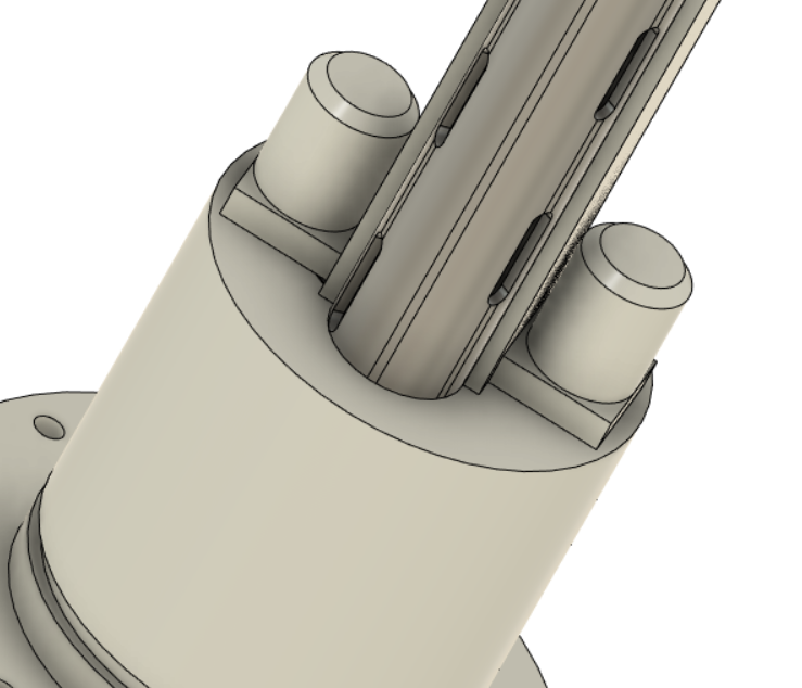](https://stanslegacy.com/uploads/images/gallery/2023-05/z6MvlvBLlrSHwMOW-image-1683164096249.png) **FIGURE 7:** Secure the O-ring support via glue to the underside of the top cover. [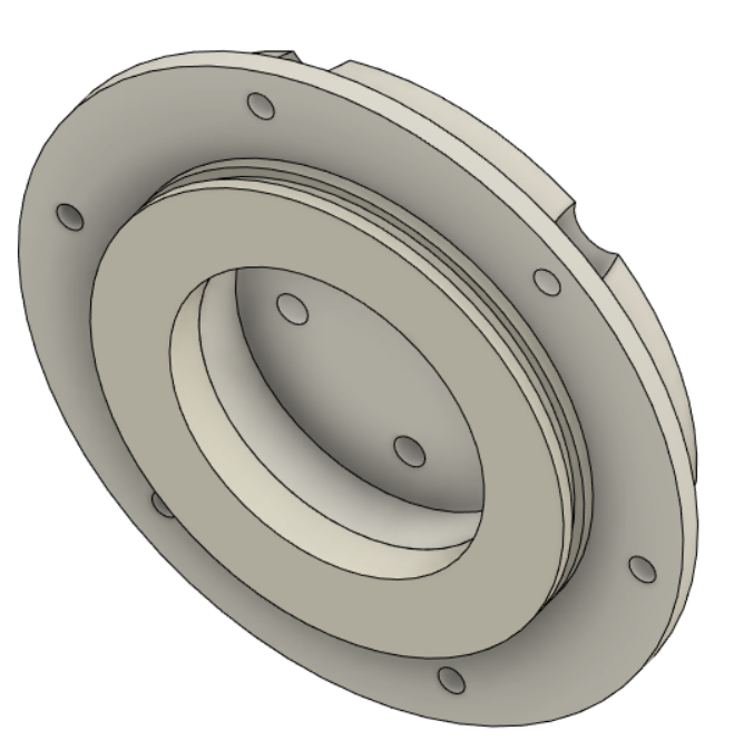](https://stanslegacy.com/uploads/images/gallery/2023-05/0GUEca2QRbiOC1Zr-image-1683164216496.png) **FIGURE 8:** Place top cap onto SR block. [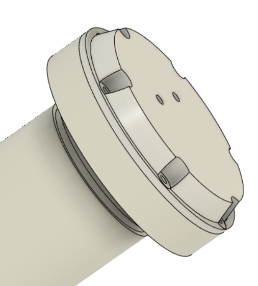](https://stanslegacy.com/uploads/images/gallery/2023-05/T7Rkjk0X3oetSOHJ-image-1683164275593.png) # Stan Meyer Machining Template STLs_5-22-2024Please be aware that new templates will be added when DIY machining techniques are tested. Check regularly until this banner is removed - indicating the below listed have been finalized and tested.
We understand that the machining of fluted inner electrodes for the Water Resonant Cavity, Gas Resonant Cavity and inner electrode for Gas Processor, etc. are cost prohibitive to many people. Current prices here in the USA for 1 - 4 inch fluted water resonant cavity was $50/each. Inspired to give fellow Stan Meyer researchers more economic options/methods, the below templates can be 3D printed and used for DIY machining. Main tools needed will be: 1.) Creality 3D printer, which you'll need to do other things related to Stan Meyer 2.) A Dremel rotary tool - with metal cutting wheel 3.) A bench vise 4.) A 1/2" chuck cordless drill #### 4inch Water Fuel Cell Resonant Cavity Inner Electrode Machining Template: [Water 4in Resonant Cavity Inner Electrode Template.stl](https://stanslegacy.com/attachments/253) #### 4inch Water Fuel Cell Resonant Cavity Inner Electrode Plastic Insert: ##### YouTube video: [4inch DIY Machining](https://stanslegacy.com/attachments/258) #### 7inch Gas Resonant Cavity (Hydrogen Gas Gun) Inner Electrode Machining Template: [HGG In Template.stl](https://stanslegacy.com/attachments/255) #### 7inch Gas Resonant Cavity (Hydrogen Gas Gun) Outer Electrode Machining Template: [V2\_HHG Outer Template.stl](https://stanslegacy.com/attachments/254) #### 5.5inch Gas Resonant Cavity Inner Electrode Plastic Insert: #### Gas Processor Inner Electrode Machining Template: [Gas Proc In Template.stl](https://stanslegacy.com/attachments/256) #### Gas Processor Outer Electrode Machining Template: [Gas Proc Outer Template.stl](https://stanslegacy.com/attachments/257)