US Patents
WFC Patents files in the United States
- Full Patent List
- Solar Heating System #3,970,070
- MultiStage Solar Storage System #4,265,224
- Light Guide Lens #4,275,950
- Light Guide Lens #4,275,950 - Illustrations
- Hydrogen Gas Injector System For Internal Combustion Engine #4,389,981
- Hydrogen Gas Burner #4,421,474
- StartUp ShutDown For A Hydrogen Gas Burner #4,465,455
- Gas Electrical Hydrogen Generator #4,613,304
- Electrical Pulse Generator #4,613,779
- Gas Generator Voltage Control Circuit #4,798,661
- Controlled Process For The Production Of Thermal Energy From Gases And Apparatus Useful Therefore #4,826,581
- Method For The Production Of A Fuel Gas #4,936,961
- Process & Apparatus For The Production Of Fuel Gas & The Enhanced Release Of Thermal Energy From Such Gas #5,149,407
- A Hydrogen Gas Fuel And Management System For An Internal Combustion Engine Utilizing Hydrogen Gas Fuel #5,293,857
Full Patent List
SMeyer-US3970070-Solar_Heating_System
SMeyer-US4265224-MultiStage_Solar_Storage_System
SMeyer-US4275950-Light_Guide_Lens
SMeyer-US4389981-Hydrogen_Gas_Injector_System_For_Internal_Combustion_Engine
SMeyer-US4421474-Hydrogen_Gas_Burner
SMeyer-US4465455-StartUp_ShutDown_For_A_Hydrogen_Gas_Burner
SMeyer-US4613304-Gas_Electrical_Hydrogen_Generator
SMeyer-US4613779-Electrical_Pulse_Generator
SMeyer-US4798661-Gas_Generator_Voltage_Control_Circuit
SMeyer-US4936961-Method_For_The_Production_Of_A_Fuel_Gas
Solar Heating System #3,970,070
United States Patent
Meyer et al.
Patent No: 3,970,070
Date: July 20, 1976[54] SOLAR HEATING SYSTEM
[76] Inventors: Stanley A. Meyer, 2931 Bryden Road; Stephen R. Gray, 2722 Allegheny Ave., both of Columbus, Ohio 43209[22] Filed: Sept. 3, 1975
[21] App. No.: 610,051
[52] U.S. Cl. ................................. 126/271; 350/96 B
[51] Int. Cl. ..................................... F24J 3/02
[58] Field of Search .................... 237/1 A; 126/270, 271; 350/96 B[56] References Cited
UNITED STATES PATENTS
1,951,403 Goddard .......... 126/271
1,969,839 Goddard .......... 126/271
2,213,894 Barry ............... 126/271
3,046,414 Sandness ........ 126/270
3,252,456 Bohn Jr. .......... 126/271
3,780,722 Swet .............. 126/270Primary Examiner — Kenneth W. Sprague
Attorney, Agent, or Firm — Cennamo Kremblas & Foster
[57] ABSTRACT
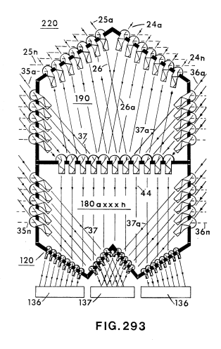
A solar heating system comprising a lens collector arrangement, an insulation area, and a storage section positioned in an enclosing structure, and an associated utilization means. The collector lens is an array of light guide lenses having internal high and low refractive surfaces. The array is contoured in a capping relationship over a focusing lens to provide an extremely high concentration of solar energy irrespective of the angle of the sun. The light guide lenses increase by several orders of magnitude the amount of solar energy striking the surface of the focusing lens. The focusing lens is a plurality of flat surface type of lenses stacked one over the other in spaced relationship and operable to concentrate the solar energy to a central region. Surrounding the perimeter of the plurality of focusing lenses in an array, in a "wall" configuration, of light guide lenses similar in construction to the aforesaid capping light guide lenses. The angle of the reflective surfaces of the capping lenses and the wall lenses is such as to receive and direct to the focusing lenses the maximum amount of radiation at all times of the day and season. The insulation area is positioned between the collector lens and the storage section to provide a convective barrier for the storage area without inhibiting the passage of solar radiation. The storage section is of a high absorptive material with an auxiliary conventional heat source.
SOLAR HEATING SYSTEM
CROSS REFERENCE
The "Light Guide Lens" of the co-pending application filed Sept. 3, 1975, by the same inventors herein and given Ser. No. 609,928, is that utilized in the present invention.
BACKGROUND
With the energy crisis created by the impact of the natural resources shortage, together with the anticipated depletion of the natural resources, a considerable amount of effort has been directed to other forms of energy. Although there are several other forms of energy, the emphasis has been placed on solar energy as the most logical heat source. Consequently, there are on the market many so-called solar furnaces.
These prior art devices generally comprise a focusing lens, a medium - either air or liquid - to be heated, in some instances a storage tank, and in other instances a reflective surface such as a mirror and/or a reflector.
Although these solar furnaces are operable and in certain instances commercially operable, they are not without their attendant disadvantages. Principally the problem area is a lack of a sufficient concentration system for the incident solar energy, directivity relative to the angle of the sun, and a storage system with a capacity to carry the system on cloudy days. The problem related to the concentration of the solar energy is with the lens and its reflecting surfaces and the response of the system to the low angles of the sun.
Further, the prior art systems generally utilize the solar radiation to heat either a liquid or air directly and then utilize the heated air or water for the intended purpose. Storage systems are much fewer and are of the indirect type, that is, the heated excess air or liquid is placed in a storage medium. These prior art storage systems are very simple in structure and somewhat crude. Very little advance in the art has been made with storage systems.
Although perhaps in some future period of time solar energy may be a complete substitute for other forms of energy, today solar energy, at best, is a supplement to or an alternate source of energy. Nonetheless, the failures of the prior art to recognize the practical usefulness of solar energy systems resulted in commercial systems that are extremely expensive but, yet, of only a minimal and questionable value.
SUMMARY OF INVENTION
The invention comprises in its most general aspects a unitary air/liquid tight cylindrical enclosure that houses a combination of components that are responsive sequentially to solar radiation. The system provides a heat source with a larger capacity and operable for an extended period of time over that of the prior art. Within the cylindrical enclosure, the components comprise in the order of operability a collector lens, an insulating area, and a storage section. Utilization means for effectively utilizing the heat generated is associated with the basic combination of apparatus.
The collector lens, the insulation area, and the storage section are serially joined together and housed in an air/liquid tight cylindrical (with appropriate vents) enclosure that is insulated against heat loss.
BRIEF DESCRIPTION OF DRAWINGS
FIG. 1 is an overall schematic plan view illustrating the preferred embodiment of the present invention.
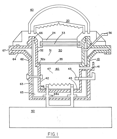
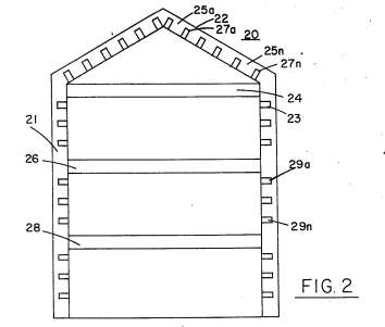
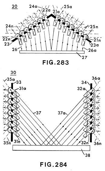
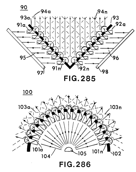
FIG. 2 illustrates a preferred lens arrangement shown generally as indicated herein for use of FIG. 1.
FIGS. 2A through 2F are various alternate embodiments of the light guide lens utilized in the present invention.
DETAILED DESCRIPTION OF DRAWINGS
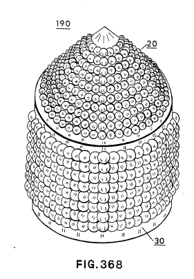
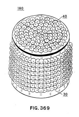
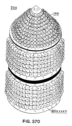
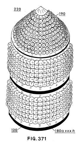
With particular reference now to FIG. 1, there is illustrated schematically a preferred embodiment of the present invention. It is most fundamental form of a solar heater comprises a housing enclosure 10, light energy concentrator 20, an insulation area 30, a heat storage section 40, and a utilization means 50.
In principle of operation, the concentration lens arrangement 20 is capable of directing a maximum amount of solar radiation to its focusing lens. The solar radiation is directed to focusing lens from all angles irrespective of the position of the sun overhead or on the horizon.
The focused solar radiation passes through an insulation barrier 30 to a thermal storage section 40. The insulation barrier 30 has a dual effect: to either inhibit the passing of thermal radiation (convective barrier). Once solar radiation is converted to thermal radiation the "heat" is stored in the thermal storage section 40, depleted by the energy demands from 50.
In actual operation the storage section 40 is the heat source. With a given capacity and the extremely efficient solar energy storage and retention, an extremely large amount of thermal energy heretofore not possible with other solar systems is obtained.
The solar heating system described above has an extremely broad and practical utilization range. However, it is not intended as "primary" energy supply but rather as a supplement to the conventional power sources.
The invention allows for continued heat storage and transfer from this stored energy and release at pre-determined times, for instance, on cloudy days or after sunset.
In the event that the storage section should exceed a certain predetermined thermal gradient (such as can occur during extended periods of "sunny" days) a heat sink arrangement is provided for the storage section to dissipate the excess energy. Additionally, a shelter arrangement and temperature-controlled unit in a conventional manner is provided for the heat storage.
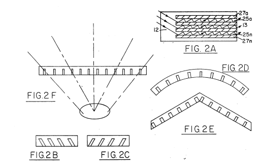 The solar energy lens 20 of FIG. 1 is shown more explicitly (again schematically) in FIGS. 2A, 2B, 2C, 2D, 2E, and 2F as alternate lens constructions which may be used. The basic method for utilizing the lenses of the preferred embodiment is to position them similar to prior art, such as in U.S. Ser. No. 609,928 filed Sept. 3, 1975.
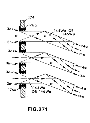
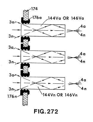
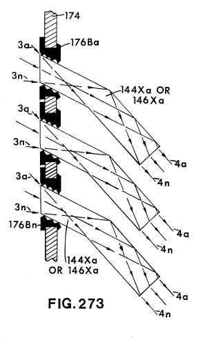
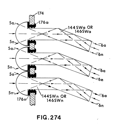
Basically, each light guide lens in this array comprises alternate high refractive (transparent) material such as glass or high refractive plastics.
The early lens 28 will receive the transmitted radiation from lens 26. Surrounding the lenses 24, 26, and 28 and the spacing therebetween is the light guide lens array 29. This lens 29, too, like the capping lens 22, is made up of high and low refractive (transparent and reflective) materials. Accordingly, in passing from lens 24 to 28, the solar radiation is confined to a shorter transition striking the reflective surfaces 29a such that the light guide lenses 22.1 direct the solar radiation to the surface of the focusing lens 24 and 28.
As indicated above, the angle of the solar radiation transmitted (passing to focusing lens 24) is dependent on the angle of the incident solar radiation, the wavelength of the solar radiation and the wavelength length of the guide (reflective surface). The light guide lens comprising the capping lens 22 are generally in the vertical or displaced from the vertical relative to the lens shown.
However, the light guides comprising the wall lens 28 are generally in both the horizontal and displaced from the horizontal relative to the angles of the sun. The primary direction of the wall light guides 22.1 in the vertical is displaced 90 degrees from the horizontal.
The light guides 26 and 28 are each arranged as flat surfaces with a high rate of absorption to solar radiation.
The primary function is to collect the solar radiation from the outermost edge and pass it inwardly, reflecting the solar radiation towards the central structure of the solar heating system.
The additional focusing lenses 26 and 28 in the preferred embodiment shown in FIG. 1 are similarly constructed to the capping lenses.
Referring again to the focusing of FIG. 1, the solar radiation focused by the focusing lens 24 is directed through the insulation area 30. The insulation area 30 is a sealed engagement with the insulator 33 comprising a pool of glass with insulating material such as salts 32. The purpose and function of the insulation area 30 is to prevent the heat energy from escaping during cloudy days or after sunset.
Particularly, the insulation area in the preferred embodiment is a liquid solution, such as a salt compound, and the heat converts the liquid solution into horizontal stratifications.
With the salt layer of the preferred embodiment, heat energy storage is maintained by the refractive material. The heat is allowed to accumulate over long periods of time during sunny days and released during cloudy days.
As indicated above, the solar radiation passes through a storage cavity filled with a liquid material or solution, such as salt. This material has a high rate of absorption to solar radiation. The stored heat is transferred for energy purposes during "off-peak" periods.
... given material having a high rate of absorption to the particular solar radiation that is desired. The lenses and salt pool provide the means for storing solar radiation.
Positioned in the lower region of the thermal storage section 40 is the heat collector and extraction assembly 47. The solar heating array 67 is conventional and may take other known forms. Connected to both sides of the collector plates 47 is the conductive thermal transfer means which is connected to heat exchanger means 50. Heat expulsion is induced by a heat utilization means 50 also conventional and commercially operable.
The solar heater of the present invention is intended as the primary heat source and may be utilized for the home or commercially. The size of the unit, although its relative size to other solar units is most small, would be increased depending on the market area to be heated. However, with the extremely efficient collector lens 28 in reality, it is only the storage area that need to be increased. Alternatively, individual units can be modularly stored, distributed throughout a given area.
It is appreciated, of course, that there may be periods of time when the sun doesn't "shine" and this may be especially disadvantageous in the winter months when the days are the shortest. Realistically, the time solar heater system of the present invention, although having a much greater and effective storage system, cannot be operated indefinitely during these "dark" periods of time when the temperature of the storage system drops below a predetermined standard. An auxiliary heat source can be connected to automatically operate, or the solar heater system itself can be cut off from energy.
The overall construction of the solar heater of the present invention is rugged, durable, and economical. The preferred embodiment was chosen to be cylindrical with a semi-flat top lens. The advantage of this configuration is that the system does not have to follow the sun. The lens is equally operative with the sun at any given angle.
It is recognized, however, that in certain climates, where it is desirable to move the solar energy for other purposes or the lenses require more exposure, more exotic glass or plastic dome lens applications may be constructed. The cover 61 of FIG. 6 can be replaced, if desired, with the lens 62 in the preferred embodiment, which can comprise metal coverings with a corrugated outer portion that supports the solar radiation system, and the lens has a cover frame that supports the lens.
It should be understood that other forms of lenses, including glass or synthetic plastic materials, can be employed for the focusing lens 28, depending on the specific climatic region. The angle, refractive index, and focal length of the various lenses can be adjusted accordingly to the sun's intensity.
It is to be noted that the present invention is illustrative only and that other modifications may be had therein without departing from the true spirit and scope of the invention.
What is claimed is:
-
A solar heater, comprising in combination:
- A collector lens positioned in the topmost region of said enclosure, and said collector lens comprising an array of light guide lenses of alternating high and low refractive material and focusing lens.
- A sealed enclosure positioned in the lowermost region of said enclosure for confining a thermal storage area of high capacity and solar radiant energy to thereby convert said solar radiant energy to thermal energy, with insulating means positioned within said enclosure intermediate of said lens and storage area, said insulating area further comprising a container with a liquid solution therein that prevents solar radiation and an isothermal convection barrier.
- And an enclosure further comprising a liquid and air seal to said lens, insulating area, and storage section, with utilization means for utilizing said thermal energy in said storage section.
-
The solar heater of claim 1 wherein said collector lens further comprises a plurality of spaced focusing lenses in a stacked relationship.
-
The solar heater of claim 2 where said focusing lenses each comprise a series of light guide prisms optically displaced from each other in various angles.
-
The solar heater of claim 3 wherein said focused prisms and wall lenses, with respect to the collector lens array and wall lens, will receive solar radiation directed inwardly and accumulated in a central focusing area to uniformly distribute said solar energy from the sun.
-
The solar heater of claim 4 wherein the primary direction of each set of light guides for said upper and lower lens sections is in the vertical with respect to the horizontal surface.
-
The solar heater of claim 4 wherein said focusing lens is circular, and the prisms are spaced circumferentially in an equal distribution.
-
The solar heater of claim 5 where said stacked focusing lenses are spaced apart by alternate regions of high refractive light guides, and at least one wall lens 28 is utilized in stacked and focused relationship to the focusing lenses 24.
-
The solar heater of claim 1 wherein said storage section further includes an auxiliary heat source thermally activated when the storage temperature exceeds a predetermined level.
Illustrations
|
|
|
MultiStage Solar Storage System #4,265,224
Light Guide Lens #4,275,950
Background
With the energy crisis created by the impact of consumption of non-renewable natural resources, together with a new emphasis on establishing clean standards associated with the usage of such natural resources, a considerable amount of effort has been directed to other forms of energy. Although there are several older forms of energy, the emphasis has been placed on solar energy as the most logical pollution-free recyclable energy source. Consequently, there are on the market many so-called solar focusing lenses.
These prior art devices generally comprise a focusing lens that is limited to a scan angle of sixty degrees (60°), and consequently are not capable of varying the effective angle while directionally focusing or dispersing the incident light radiation. The bulk of lenses of the various types are designed for use with a single stationary light source whether it be a single beam or incident light radiation in planetary array. Accordingly, the problems encountered with a single light source constantly varying its angular position are not appreciably enhanced for those instances where the problem has been encountered. Efforts have been made to have the lens "follow" the source.
In other instances where the light source is dispersed, the incident light rays upon the lens may be insufficient to render practical applications thereof. This has caused the need for others to augment the apparatus becomes extremely large, bulky, and of course expensive.
Summary of the Invention
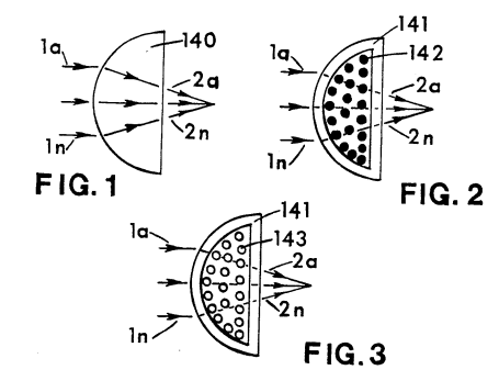
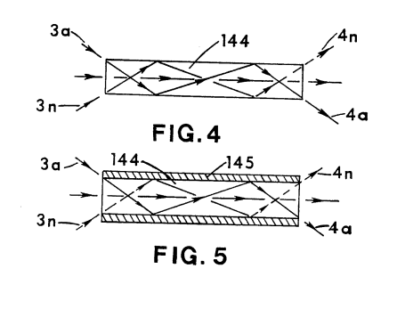
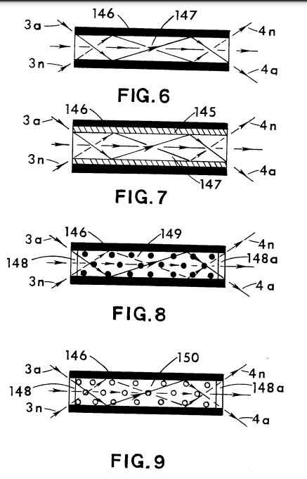
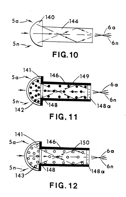
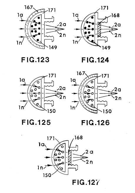
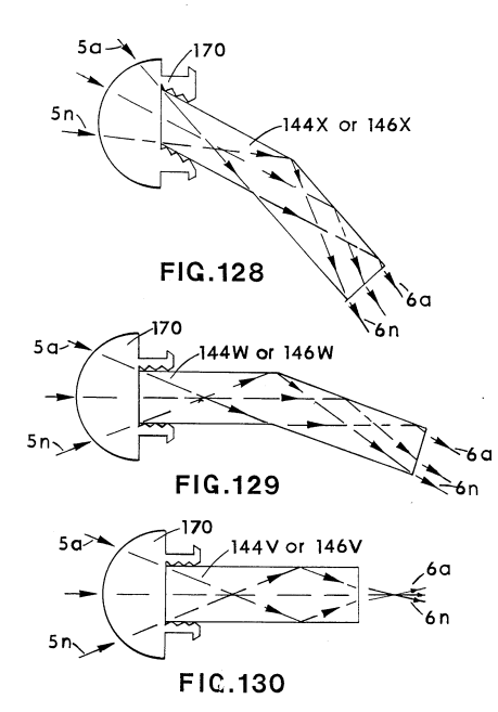
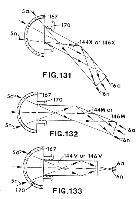
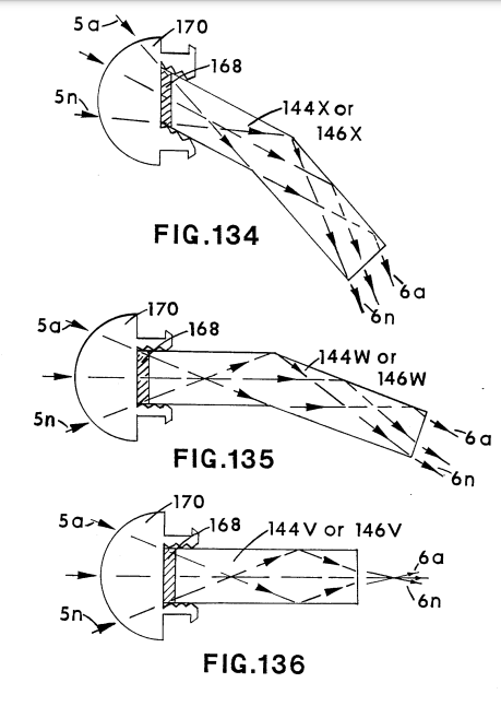
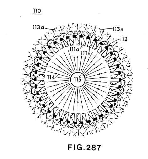
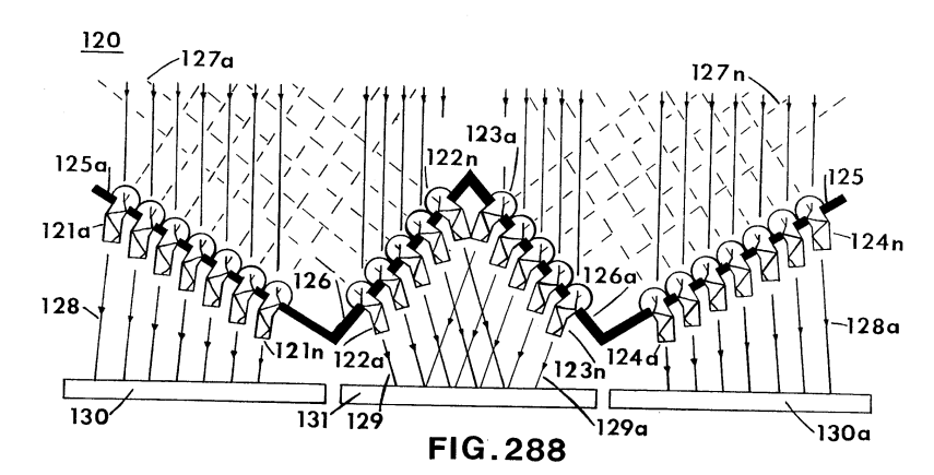
The invention comprises in its most general aspects a unitary or collector-concentrator lens enclosure that houses a combination of light-guide lenses made up of arrays of light-deflecting lenses that collects, redirects, transfers, and focuses or disperses incident light radiation to a central region irrespective of the angle of the sun during the day or season. The lens system provides a heat source with an extremely larger capacity of high energy than known solar energy and operable to overhang any span for an extended period of time over that of prior art lenses.
The solar collector-concentrator lens configuration includes a plurality of spaced focusing light-guide lenses positioned over a first flare-shaped focusing lens. Beneath the focusing lens is a heat source. Light-guide lenses in similar vertical alignment fill the spaces defined by the perimeter of the transparent outer focusing lens array, in a well-known manner to assist in the engaging and focusing of the incident light, and deflect same into the boundary structure. Each of the light-guides includes a plurality of lens formations that steer light rays from its incoming source. The light-guides having a focusing means made out of one end of different refractive index materials light guide stems. The lens includes deflectors between adjacent formations of adjacent lens means, and may be linearly or non-linearly formed.
The lens can be vertically secured or configured horizontally to a light supporting beam and attached to a thermal chamber. Multiple concentric light guide units may be included in the focal plane on the interior reflective surfaces of the guide member.
Light Guide Lens #4,275,950 - Illustrations
PDF Download: Meyer #4,275,950 Light Guide Lens.pdf
|
|
|
|
|
|
|
|
|
|
|
|
|
|
|
|
|
|
|
|
|
|
|
|
|
|
|
|
|
|
|
|
|
|
|
|
|
|
|
|
|
|
|
|
|
|
|
|
|
|
|
|
|
|
|
|
|
|
|
|
|
|
|
|
|
|
|
|
|
|
|
|
|
|
|
|
|
|
|
|
|
|
|
|
|
|
|
|
|
|
|
|
|
|
|
|
|
|
|
|
|
|
|
|
|
|
|
|
|
|
|
|
|
|
|
|
|
|
|
|
|
|
|
|
|
|
|
|
|
|
|
|
|
|
|
|
|
|
|
|
|
|
|
|
|
|
|
|
|
|
|
|
|
|
|
|
|
|
|
|
|
|
|
|
|
|
|
|
|
|
|
|
|
|
|
|
|
|
|
|
|
|
|
|
|
|
|
|
|
|
|
|
|
|
|
|
|
|
|
|
|
|
|
|
|


Hydrogen Gas Injector System For Internal Combustion Engine #4,389,981
PDF Download: Meyer #4,389,981 Hydrogen Gas Injector System For Internal Combustion Engine.pdf
ABSTRACT:
System and apparatus for the controlled intermixing of a volatile hydrogen gas with oxygen and other non-combustible gasses in a combustion system. In a preferred arrangement the source of volatile gas is a hydrogen source, and the non-combustible gasses are the exhaust gasses of the combustion system in a closed loop arrangement. Specific structure for the controlled mixing of the gasses, the fuel flow control, and safety are disclosed.
CROSS REFERENCES AND BACKGROUND:
There is disclosed in my co-pending U.S. patent application Ser. No. 802,807 filed Sept. 16, 1981 for a Hydrogen-Generator, a generating system converting water into hydrogen and oxygen gasses. In that system and method the hydrogen atoms are disassociated from a water molecule by the application of a non-regulated, non-filtered, low-power, direct current voltage electrical potential applied to two non-oxidizing similar metal plates having water passing there-between. The sub-atomic action is enhanced by pulsing the non-regulated and non-filtered direct current voltage. The apparatus comprises structural configurations in alternative embodiments for segregating the generated hydrogen gas from the oxygen gas.
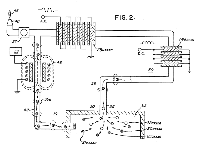
In my co-pending patent application filed May 1981, U.S. Ser. No. 262,744 now abandoned for Hydrogen-Aeration Processor, non-volatile and non-combustible gasses are controlled in a mixing stage with a volatile gas. The hydrogen aeration processor system utilizes a rotational mechanical gas displacement system 25 to transfer, meter, mix, and pressurize the various gasses. In the gas transformation process, ambient air is passed through an open flame gas-burner system to eliminate gasses and other present substances. Thereafter the non-combustible gas-mixture is cooled, filtered 30 for impurity removal, and mechanically mixed with a
pre-determined amount of hydrogen gas. There results a new synthetic gas. The synthetic gas formation stage also volume meters and determines the proper gas-mixing ratio for establishing the desired burn-rate of hydrogen gas. The rotational mechanical gas displacement system in that process determines the volume-amount of synthetic gas to be produced.
The above noted hydrogen aeration processor, of my co-pending patent application, is a multi stage system having utility in special applications. Whereas the hydrogen generator system of my other mentioned co-pending application does disclose a very simple and unique hydrogen generator.
In my co-pending patent application Ser. No. 315,945, filed Oct. 18, 1981 there is disclosed a combustion system having utility on a mechanical drive system. Particularly in one instance to drive a piston in an automotive device. There is shown a hydrogen generator for developing hydrogen gas, and perhaps other non-volatile gasses such as oxygen and nitrogen. The hydrogen gas with the attendant non-volatile gasses are fed via a line to a controlled air intake system. The combined hydrogen, non-volatile gasses, and the air after inter-mixing are fed to a combustion chamber where it is ignited. The exhaust gasses of the combustion chamber are returned in a closed loop arrangement to the mixing chamber for the mixture of volatile and non-combustible gasses. Particular applications and structural embodiments of the system are disclosed.
SUMMARY OF INVENTION:
The system of the present invention in its most preferred embodiment is for a combustion system utilizing hydrogen gas; particularly to drive a piston in an automobile device. The system utilizes a hydrogen generator for developing hydrogen gas. The hydrogen gas and other non-volatile gasses are fed to a mixing chamber also having oxygen fed thereto. The mixture is con-
trolled to regulate the burning temperature; that is, to lower the temperature velocity of the hydrogen gas to that of the commercial fuels. The hydrogen gas feed line to the combustion chamber includes a fine linear control gas flow valve. An air intake is the source of oxygen and it also includes a variable valve. The exhaust gasses from the combustion chamber are utilized in a controlled manner as the non-combustible gasses.
The hydrogen generator is improved upon to include a holding tank to provide a source of start-up fuel. Also, the hydrogen gas generator includes a switch to the power source operable from one position to another dependent upon a pressure sensing switch on the combustion chamber. The simplified structure includes a series of one-way valves, safety valves, and quenching apparatus. The combination of apparatus comprises the complete assembly for converting the standard automobile engine from gasoline (or other fuels) to the hydrogen gas mixture.
OBJECTS:
- It is accordingly a principal object of the present invention to provide a combustion system of gasses combined from a source of hydrogen and non-combustible gasses.
- Another object of the invention is to provide such a combustion system that intermixes the hydrogen and non-combustible gasses in a controlled manner and an thereby control the combustion temperature.
-
A further object of the invention is to provide such a combustion system that controls the fuel flow to the combustion chamber in s system and apparatus particularly adapted to hydrogen gas. Still other objects and features of the present invention will become apparent from the following detailed description when taken in conjunction with the drawings in which:
BRIEF DESCRIPTION OF DRAWINGS:
FIG. 1 is a mechanical schematic illustration partly in block form of the present invention in its most preferred embodiment.
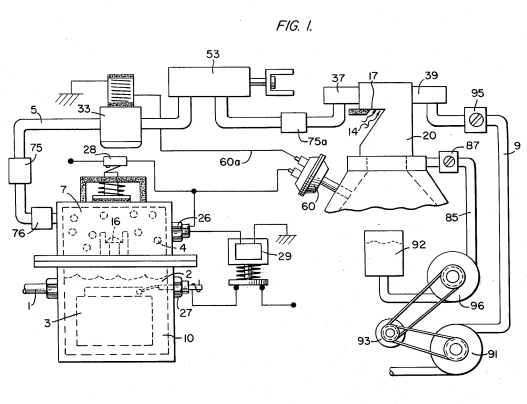
FIG. 2 is a block schematic illustration of the preferred embodiment of the hydrogen injector system of FIG. 1.
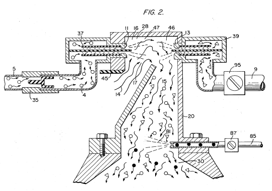
FIG. 3 is the fine linear fuel flow control shown in FIG. 1.
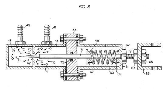
FIG. 4 is cross-sectional illustration of the complete fuel injector system in an automobile utilizing the concepts of the present invention.
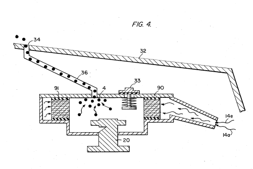
FIG. 5 is a schematic drawing in a top view of the fuel injector system utilized in the preferred embodiment.
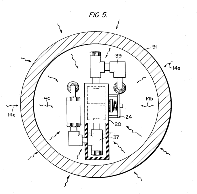
FIG. 6 is a cross-sectional side view of the fuel injector system in the present invention.
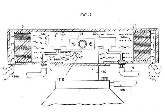
FIG. 7 is a side view of the fuel mixing chamber. 60
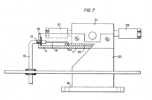
FIG. 8 is a top view of the air intake valve to fuel mixing chamber.
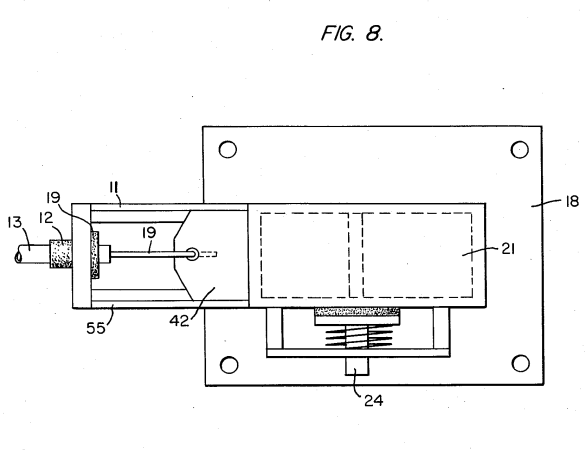
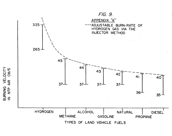
FIG. 9 is a comparison of the burning velocity of hydrogen with respect to other fuels.
DETAILED DESCRIPTION OF INVENTION TAKEN WITH DRAWINGS:
Referring to FIG. 1 the complete overall gas mixing and fuel flow system is illustrated together for utilization in a combustion engine particularly an engine utilized in an automobile.
With specific reference to FIG. 1, the hydrogen source 10 is the hydrogen generator disclosed and described in my co-pending application, supra. The container 10 is an enclosure for a water bath 2. Immersed in the water 2 is an array of plates 3 as further described in my co-pending application, supra. Applied to plates 3 is a source of direct current potential via electrical inlet 27. The upper portion 7 of the container 10 is a hydrogen storage area maintaining a predetermined amount of pressure. In this way for start up there will be an immediate flow of hydrogen gas. To replenish the expended water the generator provides a continuous
water source 1. Thereafter, the generator is operable as described in the aforesaid patent application.
The safety valve 28 is rupturable upon excessive gas build-up. Whereas the switch 26 is a gas pressure switch to maintain a predetermined gas pressure level about a regulated low-volume. The generated hydrogen gas 4 is fed from the one-
way check valve 16 via pipe 5 to a gas mixing chamber 20, wherein the hydrogen gas is inter-mixed with non-
combustible gasses via pipe line 9 from a source herein-after described.
In the event one way valve 75 should fail and there be a return spark that might ignite the hydrogen gas 4 in the storage area 7 of hydrogen generator 10, quenching assembly 76 will quench the spark and prevent such ignition. With particular reference to FIG. 2 the hydrogen gas via pipe line 5 and non-combustible gasses via pipe line 9 are fed to a carburetor (air-mixture) system 20 also
having an ambient air intake 14.
The hydrogen gas 4 is fed via line 5 through nozzle 11 in a spray 16 in to the trap area 46 of the mixing chamber 20. Nozzle 11 has an opening smaller than the plate openings in the quenching assembly 37, thereby preventing flash back in the event of sparking. The non-volatile gasses are injected into mixing chamber 20 trap area 47 in a jet spray 17 via nozzle 13. Quenching assembly 39 is operable much in the same manner as quenching assembly 37.
The ambient air is, in the preferred arrangement, the source of oxygen necessary for the combustion of the 45 hydrogen gas. Further, as disclosed in the aforesaid co-pending application the non-volatile gasses are in fact the exhaust gasses in a closed loop system. It is to be understood that the oxygen and/or the non-combustible gasses can be from an independent source.
With continued reference to FIG. 2 the gas trap area 47 is a predetermined size. In that hydrogen is lighter than air, the hydrogen will rise and become entrapped in the are 47. The size of area 47 is sufficient to contain enough hydrogen gas for instant ignition upon start up 55 of the combustion engine.
It will be noted that the hydrogen gas is injected in the uppermost region of the trap area 47. Hydrogen rises at a much greater velocity than oxygen or non-combustible gasses; perhaps three times or greater. Therefore, if the hydrogen gas entered the trap area 47 (mixing area) at its lowermost region the hydrogen gas would rise so rapidly that the air could not mix with the oxygen. With the structure shown in FIG. 2 of the trap area 47, the hydrogen gas is forced downwardly into the air intake 15. That is, the hydrogen gas is forced downwardly into the upwardly forced air and readily mixed therewith.
The ratio of the ambient air (oxygen) 14 and the non-combustible gas via line 9 is a controlled ratio and determined by the particular engine. Once the proper combustion rate is determined by the adjustment of valve 95 for varying the amount of the non-combustible gas and the adjustment of valve 45 for varying the amount of the ambient air, the ratio is maintained.
In a system wherein the non-combustible gasses are the exhaust gasses of the engine in a closed loop- arrangement, and wherein the air intake is under the control of the engine, the flow velocity and hence the air/non-combustible mixture, is maintained by the acceleration of the engine.
The mixture of air with non-combustible gasses becomes the carrier for the hydrogen gas. That is, the hydrogen gas is superimposed on the air/non-combustible mixture. By varying the amount of hydrogen gas superimposed on the air/non-combustible mixture, the r.p.m. of the engine is controlled. Reference is made to FIG. 3 illustrating precisely in a side view cross-section the fine linear fuel flow control The hydrogen gas 4 enters chamber 43 via gas inlet The hydrogen gas passes from chamber 43. The hydrogen gas passes from chamber 43 to chamber 47 via port or opening 42. The amount of gas passing form chamber 43 to chamber 47 is controlled by controlling the port opening 2.
The port opening is controlled by the insertion there through the linearly tapered pin 73. The blunt end of pin 73 is fixed to rod 71. rod 71 passed by supporting O-ring 75, through opening 81 in housing 30, to manual adjustment mechanism 83. The spring 49 retains the rod 71 is a fixed position relative to the pin 73 and opening 42. Upon actuating the mechanism 83, the pin 73 will recede from the opening 42 there by increasing the amount of gas passing from chamber 43 to chamber 47. The stops 67 and 69 maintain spring 49 in its stable position. The position of the pin 73 in a fixed position relative to opening 42 is adjusted via threaded nuts 63 and 67 on threaded rod 61. That is, the threaded adjustment controls the idle speed or permits the minimum
amount of gas to pass from chamber 43 to chamber 47 for continuous operation of the combustion engine.
Referring now to FIG. 8 there is illustrated the air adjustment control for manipulating the amount of air passing into the mixing chamber 20. The closure 21 mounted on plate 18 has an opening 17 on end 11 thereof. Slide-ability mounted over said opening 17 is a plate control 42. The position of the plate relative to the opening 17 is controlled by the position of the control rod 19 passing through a grommet 12 to control line. In event of malfunction that may cause combustion of gasses in mixing chamber 20, release valve 24 will rupture.
With reference now to FIG. 4, in the event hydrogen gas 4 should accumulate in the mixing chamber 20 to excessive pressure, an escape tube 36 connected to a port 34 on the automobile hood 32 permits the excess hydrogen gas to safely escape to the atmosphere. In the event of a malfunction that may cause combustion in the mixing chamber 20, the pressure relief valve 33 will
rupture expelling hydrogen gas without combustion. In the constructed arrangement of FIG. 1, there is illustrated a gas control system that may be retrofitted to an existing automobile internal combustion engine without changing or modifying automobile's design parameters or characteristics.
The flow of the hydrogen volatile gas is, of course, critical; therefore, there is incorporated in line 5 a gas flow valve 53 (FIG. 1) to adjust the hydrogen flow. Gas flow valve is described in detail with reference to FIG. 3. The intake air 14 may be in a carburetor arrangement with an intake adjustment 55 that adjusts the plate 42 opening and also more fully described with reference to
FIG. 8. To maintain constant pressure in hydrogen gas storage 7 in the on-off operation of the engine, the gas flow control valve is responsive to the electrical shut-off control 33. The constant pressure permits an abundant supply of gas on start up and during certain periods of running time in re-supply.
The switch 33 is in turn responsive to the vacuum control switch 60. During running of the engine vacuum will be built up which in turn leaves switch 33 open by contact with vacuum switch 60 through lead 60a. When the engine is not running the vacuum will de- 20 crease to zero and through switch 60 will cause electrical switch 33 to shut off cutting off the flow of hydrogen gas to the control valve 53. As low-voltage direct current is applied to safety valve 28, solenoid 29 is activated. The solenoid applies 25
a control voltage to the hydrogen generator exciter 3 via terminal 27 through pressure switch 26. As the electrical power activates electric solenoid 29, hydrogen gas is caused to pass through flow adjustment valve 16 and then outlet pipe 5 for utilization. The pressure differential hydrogen gas output to gas mixing chamber 20 is for example 30 lbs. to 15 lbs. Once hydrogen genera-
for 10 reaches an optimum gas pressure level, pressure 26 shuts off electrical power to the hydrogen exciters. exciters. If the chamber pressure exceeds a predeter-35 mined level, the safety release valve 28 is activated disconnecting the electrical current and thereby shutting down the entire system for safety inspection.
Hydrogen Gas Burner #4,421,474
PDF Download: Meyer #4,421,474 Hydrogen Gas Burner.pdf
CROSS REFERENCE:
The hydrogen/oxygen generator utilized in the present invention is that disclosed and claimed in my co- pending patent application, Ser. No.: 302,807, filed: Sept. 16, 1981, for HYDROGEN GENERATOR SYSTEM. In that process for separating hydrogen and oxygen atoms from water having impurities, the water is passed between two plates of similar non-oxidizing metal. No electrolyte is added to the water. The one plate has placed thereon a positive potential and the other a negative potential from a very low amperage direct-current power source. The sub-atomic action of the direct current voltage on the non-electrolytic water causes the hydrogen and oxygen atoms to be separated- —and similarly other gasses entrapped in the water such as nitrogen. The contaminants in the water that are not released are forced to disassociate themselves and may be collected or utilized and disposed of in a known manner.
The direct current acts as a static force on the water molecules; whereas the non-regulated rippling direct current acts as a dynamic force. Pulsating the direct current further enhances the release of the hydrogen and oxygen atoms from the water molecules.
In my co-pending patent application, Ser. No.: 262,744, filed: May 11, 1981, for: HYDROGEN AIR- DATION PROCESSOR, there is disclosed and claimed the utilization of the hydrogen/oxygen gas generator. In that system, the burn rate of the hydrogen gas is controlled by the controlled addition of non-combustible gasses to the mixture of hydrogen and oxygen gasses.
PRIOR ART:
The electrolysis process for generating hydrogen and oxygen gas is well known in the art. It is, of course, further understood with a proper mixture of oxygen gas, the hydrogen gas is combustible and under ideal conditions a flame, may be had. Reference is made to USS. Pat. No.: 4,184,931. However, in that the burning velocity of hydrogen is 265-325 cm./sec. versus 37~45 cm./sec. of that of gasoline, the velocity of hydrogen is so great that the hydrogen ensuing from a nozzle will not under ordinary circumstances sustain a flame.
Therefore, to sustain a flame at a nozzle attached to a hydrogen generator the burning velocity of the hydro- gen gas must be reduced.
It has been found that all water in its natural state whether it be tap water, well water, sea water, or fresh water is a saturate of ambient air. Further, in that ambient air contains a substantial amount of nitrogen, all natural water will have entrapped therein nitrogen. Again, the percentage of nitrogen entrapped in natural water has been determined to be a fixed percentage and very uniform at seventeen (17%) percent—irrespective of the source of the water or its impurities. Hence, a natural water gas analysis will show a seventeen percent of nitrogen relative to the hydrogen and the oxygen.
The nozzle connected to the collection chamber via an appropriate line, has a port opening of a controlled size and configuration, related to the size of the flame and the temperature and velocity of the burning gas mixture. To maintain the flame, that is to prevent blown out, additional nozzles are included when the overall flame size is to be increased.
SUMMARY OF INVENTION:
The present invention is for a hydrogen gas burner and comprises a combustion chamber for the mixture of hydrogen gas, ambient air, and non-combustible gasses. The mixture of gasses is ignited and burns at a retarded velocity rate and temperature from that of hydrogen gas, but at a higher temperature rate than other gasses. The extremely narrow hydrogen gas mixture flame of very high temperature is restricted from the utilization means by a heat absorbing barrier. The flame strikes the barrier which in turn disperses the flame and absorbs the heat therefrom and thereafter radiates the heat as extremely hot air into the utilization means.
Positioned on the opposite side of the heat radiator/- barrier is a hot air trap. A small portion of the radiated heat is captured and returned to the combustion chamber as non-combustible gasses. Valve means in the re- turn line regulates the return of the non-combustible gas in a controlled amount to control the mixture. The present invention is. principally intended for use with the hydrogen generator of my co-pending patent application, supra; but it is not to be so limited and may be utilized with any other source of hydrogen gas.
OBJECTS:
- It is accordingly a principal object of the present application.to provide a hydrogen gas burner that has a temperature controlled flame and a heat radiator/barrier.
- Another object of the present invention is to provide a hydrogen gas burner that is capable of utilizing the heat from a confined high temperature flame.
- Another object of the present invention is to provide a hydrogen gas burner that is retarded from that of hydrogen gas, but above that of other gasses.
- Another object of the present invention is to provide a hydrogen gas burner that utilizes the exhaust air as non-combustible gas for mixture with the hydrogen gas.
- Another object of the present invention is to provide a hydrogen gas burner that is simple but rugged and most importantly safe for all intended purposes.
- Other objects and features of the present invention will become apparent from the following detailed description when taken in conjunction with the drawings in which:
BRIEF DESCRIPTION OF DRAWINGS:
- FIG. 1 is an overall cross-sectional view of the present invention in its most preferred embodiment.
- FIG. 2 is a graphical illustration of the burning of various standard fuels with that of hydrogen velocities.
DETAILED DESCRIPTION OF INVENTION:
With particular reference FIG. 1 there is illustrated in a schematic. cross-section the principals of the present invention.
Figure 1 is an overall cross-sectional view of the present invention in its most preferred embodiment.
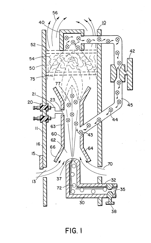
The structure of the preferred embodiment comprises a housing 10, having an igniter 20 extending through the wall 11 thereof. A combustion chamber 60 positioned within the housing 10 has a first open end 62. A hydrogen gas 72 inlet 30 directs hydrogen gas via port 37 from a source 35 to the inlet 62 of the combustion chamber 68. Also directed to the same inlet 62, and assisted by flanges 64 and 66, is ambient air 70 entering through ports 13 in the housing 10. Adjacent the opposite end of the combustion chamber 60 the gas mixture 75 is ignited by the ignitor 20 to produce flame 77.
The velocity of the flame 77 causes it to strike and penetrate the barrier/radiator 50. The barrier 50 is of a material, such as metallic mesh or ceramic material, to disperse therein the flame and in turn become saturated with heat. The flame 77 is of a size sufficient to be dispersed throughout the barrier 50, but yet, not penetrate through the barrier 50. Radiated from the surface 52 of the barrier 50 is super-heated air 56 (gasses) to be passed on to a utilization device. Adjacent to surface 52 of barrier/radiator 50 is a hot air trap 40 with closed loop line 45 returning non-combustible gas 44 to the combustion chamber 60. Control valve 42 is intermediate the line 45.
In operation of the preferred embodiment hydrogen gas, 72, emitted from the nozzle 37 is directed to the combustion chamber 60. The flanges 64 and 66 on the open end of housing 63 of the combustion chamber 60 enlarges the open end of 62. In the enlargement ambient air from the opening 13 in the housing 10 is also directed to the combustion chamber 60. The ambient air and hydrogen traverses the opening 43 and further mixes with the non-combustible gas 44 from the closed loop line 45 with the hot air trap 40. The mixture of hydrogen gas 72, ambient air 70, and non-combustible gas 44, is ignited by the ignitor 20 having electrical electrodes 21 and 23. Upon ignition flame 77 ensues.
The mixture is controlled with each of three gasses. That is, the line 32 from the hydrogen source 35 has a valve 38 therein for controlling the amount of hydrogen 72 emitted from the nozzle 37. The opening 13 has a plate adjustment 15 for controlling the amount of ambient air 60 directed to the combustion chamber 60, and the closed-loop line has valve 42, as aforesaid, for con- trolling the amount of non-combustible gasses in the mixture. It can be appreciated that the temperature of the flame 77 and the velocity of the flame 77 is a function of the percentage of the various gasses in the mixture. Ina practical embodiment, the flame 70 temperature and velocity was substantially retarded from that of a hydrogen flame per se; but yet, much greater than the temperature and velocity of the flame from the gasses utilized in a conventional heating system.
To maintain a sufficient pressure for combustion of the hydrogen gas mixture with a minimum of pressure (for safety) and to limit blowout, the nozzle 37 opening 39 is extremely small. As a consequence, if the hydro- gen gas were burned directly from the nozzle 37, the flame would be finite in diameter. Further, its velocity would be so great it is questionable whether a flame could be sustained. The mixing of ambient air and non-combustible gas does enlarging the flame size and does reduce its velocity. However, to maintain a flame higher in temperature and velocity than the conventional gasses, the size and temperature of the flame is controlled by the aforementioned mixture. Therefore, to utilize the flame 77 in a present day utilization means, the flame is barred by the barrier 50. The barrier 50 is of a material that can absorb safely the intense flame 77 and thereafter radiate heat from its entire surface 52. The material 54 can be a ceramic, metallic mesh or other heat absorbing material known in the art. The radiated heat 56 is directed to the utilization means.
As aforesaid, the mixture of gasses that are burned include non-combustible gasses. As indicated in the above-noted co-pending patent applications, an excel- lent source of non-combustible gasses are exhaust gases. In this embodiment, the trap 50 entraps the hot air 74 and returns the same, through valve 42, to the combustion chamber 60 as non-combustible gas.
FIG. 2 is a graphical illustration of the burning of various standard fuels with that of hydrogen velocities.
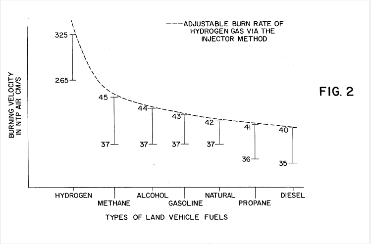
With reference to FIG. 2 there is illustrated the burning velocity of various standard fuels. It can be seen the common type of fuel burns at a velocity substantially less than hydrogen gas. The ratio of hydrogen with non-combustible oxygen gasses is varied to obtain optimum burning velocity and temperature for the particular utilization. Once this is attained, the ratio, under normal conditions, will not be altered. Other uses having different fuel burn temperature and velocity will be adjusted in ratio of hydrogen- /oxygen to non-combustible gasses in the same manner as exemplified above.
Further, perhaps due to the hydrogen gas velocity, there will occur unburnt gas at the flame 77 output. The barrier 50, because of its material makeup will retard the movement and entrap the unspent hydrogen gas. As the superheated air 77 is dispersed within the material 54, the unspent hydrogen gas is ignited and burns therein. In this way the barrier 50 performs somewhat in the nature of an after burner.
CLAIMS:
1. A hydrogen gas burner for utilization as a heat source comprising:
- A housing having a double open-end combustion chamber positioned therein,
- A source of hydrogen gas and a nozzle connected thereto for directing the hydrogen gas into one end of said combustion chamber, ambient air intake means in said housing positioned to direct ambient air into said combustion chamber, and a source of a non-combustible gas, return line means for returning said non-combustible gas to said combustion chamber for mixing with said hydrogen gas and said ambient air, an ignitor for igniting said mixture of gasses,
- A barrier positioned adjacent to other open-end of said combustion chamber, said ignited mixture of gasses superheating the air in said housing and directing the same to said barrier, said barrier further comprising a heat dissipating surface to disperse heated air to the utilization means. :
2. The hydrogen gas burner of claim 1 wherein said source of non-combustible gas further comprises a hot air trap adjacent to the heat dissipating surface of said barrier and a return line from said trap to said combustion chamber.
3. The hydrogen gas burner of claim 1 wherein said return line further comprises valve means for control- ling the amount of non-combustible gas entering said combustion chamber.
4. The hydrogen gas burner of claim 1 wherein said ambient air intake means is positioned in said housing to provide ambient air to said combustion chamber together with said hydrogen gas.
5. The hydrogen gas burner of claim 1 wherein said ambient air intake means in said housing further comprises a valve means for controlling the amount of ambient air entering said combustion chamber.
6. The hydrogen gas burner of claim 1 wherein said source of hydrogen gas further comprises a valve means for controlling the amount of hydrogen gas introduced to said combustion chamber.
7. The hydrogen gas burner of claim 1 wherein said hydrogen gas, said ambient air, and said non-combustible gasses are controlled in amount to a predetermined ratio dependent upon the desired velocity and temperature of the ensuing flame.
8. The hydrogen gas burner of claim 1 wherein said nozzle has a port opening of a controlled size to provide a constant flame without blowout.
9. The hydrogen gas burner of claim 1 wherein said barrier comprising a heat saturating material with a heat dissipating surface.
10. The hydrogen gas burner of claim 9 wherein said heat absorbing/dissipating barrier comprises a ceramic material.
11. The hydrogen gas burner of claim 9 wherein said heat absorbing/dissipating barrier comprises a metallic mesh material. .
12. The hydrogen gas burner of claim 1 wherein said opening in said combustion chamber further comprises flange means for directing said hydrogen gas and said ambient air thereto. .
13. The hydrogen gas burner of claim 9 wherein said barrier retards unspent. hydrogen gas atoms and thereafter ignites the same.
StartUp ShutDown For A Hydrogen Gas Burner #4,465,455
PDF Download: Meyer #4,465,455 StartUp ShutDown For A Hydrogen Gas Burner.pdf
ABSTRACT:
System for flame start-up/shut-down for a hydrogen gas mixture burner. An electrical probe igniter positioned adjacent the gas port outlet. On demand the igniter is actuated to heat and electrically heat a thermal switch. Responsive electronic controls actuate the appropriate valves and circuits for operational start-up. Upon the ignition of the generated hydrogen gas mixture, a second thermal probe is heated by the flame to deactivate the ignition and start-up circuits. After demand the second thermal probe cools and the circuit is restored for start-up again. A safety probe positioned in the flame is quiescent. In the event of demand time shut-down, the safety probe will activate the circuits for restart. If failure to start-up continues for a predetermined time, the safety probe circuit will effect permanent shut-down.
CROSS REFERENCES:
In the non-electrolysis process disclosed and claimed in my co-pending patent application, Ser. No. 302,807, Filed: Sept. 16, 1981, For: HYDROGEN GENERATOR SYSTEM, for separating hydrogen and oxygen atoms from water, water is passed between two plates of similar non-oxidizing metal. The one plate has placed thereon a positive potential and the other a negative potential from a very low-direct-current power source. The sub-atomic action of the direct current voltage causes the hydrogen and oxygen atoms to be separated. The contaminants in the water are forced also to disassociate itself and may be collected or utilized and disposed of. This in turn lends the process to recombining the hydrogen and oxygen into pure water.
The direct current voltage applied to the plates is non-regulated and non-filtered. The direct current acts as a static force on the water molecules; whereas the rippling direct current voltage acts as a dynamic force. Pulsating the direct current further acts as a dynamic force and enhances considerably the splitting of the 25 atoms from the water molecules. An increase in voltage potential further increases the hydrogen output. Certain plate arrangements and configurations with graphical illustration or relative efficiency are disclosed.
In my co-pending patent application, Ser. No. 30 422,495, Filed: Sept. 24, 1982, For: PERIODIC FLUSH SYSTEM FOR NON-ELECTROLYSIS HYDROGEN GENERATOR, there is disclosed control apparatus and electrical circuitry for periodically shutting down the hydrogen generator for flushing out the 35 accumulated contaminates. The shut-down is in a sequential step-by-step operation. After the flushing is complete, the hydrogen generator is started up and, again, in a sequential step-by-step operation. Although the functions are numerous, the most critical is the 40 opening and closing of the gas valves, and the switching on and off of the electrical circuitry to the exciter elements.
BACKGROUND:
Heating and air environmental systems of the prior art have included sensing systems for flame-out, power loss or the like. These systems do provide some form of shut-down upon occurrence of a malfunction. However, the prior art systems are either of gas, oil, or electrical. Although a gas or oil furnace will utilize electrical circuitry for a blower, the energy, whether gas, oil, or electric, is supplied either by a utility or in bulk. None of the prior art systems generate the energy that is used in the heating or air control system. Accordingly, no monitoring systems for the generator systems are known in the prior art, that are applicable heating or air control systems.
SUMMARY OF INVENTION:
The present invention in its preferred embodiment provides a monitoring system and a start-up/shut-down circuitry and apparatus for a hydrogen gas burner. The system is distinctive in that the hydrogen generator is a demand system; that is, hydrogen gas is generated only when the thermostat (or other gauge) dictates the energy is needed. Accordingly, the start-up is the start-up of the energy generating system and thereafter starting the igniter to ignite the hydrogen gas mixture. Further, although the prior systems start-up on demand; none have a need for periodic shut-down.
The present invention is a start-up/shut-down system for an energy generator and for the utilization of the
energy generated. The function in addition to demand is periodic. Then, again, the same procedure is followed upon the occurrence of malfunction. The apparatus comprises an igniter in the flame path that upon actuation heats a thermal probe that controls the electrical/electronic circuitry for opening and closing the various controls and switches. Another probe deactivates the ignition and start-up upon completing the function. A safety probe positioned in the flame path is time controlled to start-up in the occurrence of a flame-out, if failure occurs in the attempt to retract within a given period of time the entire system is shut-down.
OBJECTS:
- It is a principal object of the present invention to provide a monitoring and control system for start-up and shut-down of an energy generator system.
- Another object of the present invention is to provide such a control system that is operable upon demand, periodically operable, and operable upon occurrence of a malfunction.
- A further object of the invention is for a monitoring and control system that distinguishes between an accidental flame-out and a flame-out caused by malfunction of the system.
- A further object of the invention is for a monitoring and control system that provides a restart function upon accidental flame-out. Other objects and features of the present invention will become apparent from the following detailed description when taken in conjunction with the drawings in which:
BRIEF DESCRIPTION OF DRAWINGS:
FIG. 1 schematically depicts a preferred embodiment of the invention of a hydrogen gas mixture burner incorporating the features of the invention.
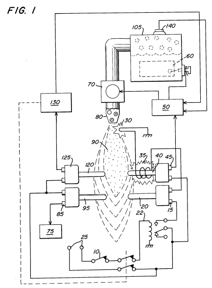
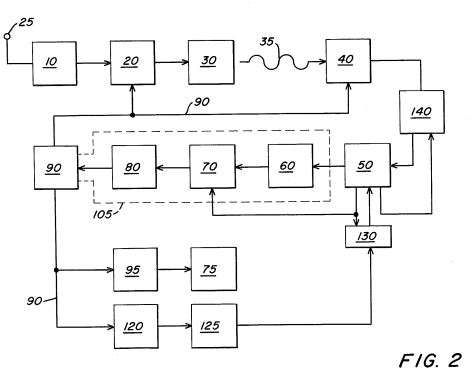
FIG. 2 is a schematic block diagram of the preferred embodiment in a complete operational generator system.
DETAILED DESCRIPTION OF DRAWINGS:
With reference to FIG. 1 there is a illustrated schematically the mechanical/electrical apparatus of the system of the preferred embodiment of the invention taken in conjunction with the hydrogen generator of my co-pending patent application, supra. In FIG. 2 the electrical circuitry and actuating valves and the like are depicted in a sequential schematic block type of arrangement. Referring to FIG. 1, together with FIG. 2, the preferred embodiment of the present invention may now be described. the thermal probe switch 20, before start-up, is in a normally closed position. Upon the demand for energy, dictated by the thermostat 10 control, the relay 22 is closed, applying electrical power from source 25 to the electrical spark igniter 30 through the closed thermal probe 20. Upon the spark igniter 30 attaining the appropriate temperature, the radiant heat from coil 35 heats the thermal probe 40.
As the thermal probe 40 heats, the normally open switch 45 closes and in turn actuates the electrical control circuit 50. The control circuit 50 closes the circuit to apply electrical power to the exciters 60 in the non-electrolysis hydrogen generator 105. In sequence, and upon attaining appropriate pressure from the gasses generated as indicated by pressure valve in the hydrogen generator 105, also illustrated in FIG. 2 in dotted line block, the gas outlet valve 70 is opened, permitting gas to be expelled through a nozzle assembly 80. Upon the gas making contact with the heated electrical spark igniter 30, the hydrogen gas mixture, expelled from the controlled port opening in nozzle assembly 80 is ignited into a continuous extremely high temperature flame 90. The thermal probe 95 immediately begins to heat and after attaining the predetermined temperature the fan assembly 75 is actuated by the closure of relay 85.
The flame 90 having been ignited and burning, causes the thermal probe 20 to become heated and thereby opening its relay 15. In turn, the voltage applied to the electrical spark igniter 30 is terminated by the open relay 15. Upon the demand from the thermostat 10 being reached the relay 22 is opened thereby cutting off the voltage 25 to the thermal probe switch 20. Sequentially
the electrical control circuit 50 opens the circuit providing voltage to the exciters 60; thereby shutting gas outlet valve 70 to terminate the flame 90. Thereafter the circuit is ready for start-up again upon demand from the thermostat 10, as aforesaid.
A safety probe 120 is also positioned in the flame 90. During operation of the system under demand from the thermostat control 10, the probe 120 will remain heated. In this condition the attendant relay 130 is inoperative. If for some reason the flame 90 should be extinguished during the demand period the safety probe 120 will quickly cool and in sequence the attendant relay 130
will open. Relay 130 connected to relay 22 in the power circuit will act in place of the demand thermostat 10,that is, the relay 130 will override the demand thermostat 10. The circuits and functions will follow as above described for start-up in the event the flame-out was accidental.
The safety control system further includes a timer circuit and thermostat 125 that will permit the probe 120 to attain its temperature within a given period of time. If the probe 120 does not attain its temperature the same start-up procedure will follow again, within a given period of time. The timer 125 is so set that unless the probe 120 attains the appropriate temperature within the given period of time the entire circuitry is shut down permanently. This denotes a major failure in the system and not a simple flame-out. Finally, in the unlikely event of pressure build-up upon malfunction, there is provided a safety relief valve 140.
CLAIMS:
A start-up/shut/down circuit for activating and deactivating a non-ionic hydrogen generator burner system on demand, comprising:
- A thermostatic control demand circuit, a gas nozzle connected to the generated gas output of said hydrogen generator and a controlled size port in said nozzle for confining and controlling the hydrogen gas expelled therefrom,
- An igniter positioned in the projective path of said nozzle,
- An electrical heating element adjacent said igniter,
- A voltage source and means connected to said source for applying voltage to said heating element for heating said igniter upon demand as predetermined by said demand circuit,
- A heat sensing element, including heat responsive switching means, responsive to the temperature of said igniter electrical heating element,
- An electrical control circuit connected to said heat responsive switching means,
- A direct current voltage source and switching means for applying voltage from said voltage source to said hydrogen generator, said switch activated by said electrical control circuit upon said ignitor attaining a predetermined temperature, and gas valve outlet, and pressure sensing means on said hydrogen generator, said electrical control circuit, including means for actuating said outlet valve, to permit the generated gasses to be expelled from said nozzle upon said gasses generated by said hydrogen generator attaining a predetermined pressure, said expelled gasses from said nozzle, upon contact with said heated igniter, being ignited into a continuous flame,
- A second heat responsive sensory element positioned in the path of said ignited gasses including heat responsive switch means connected to said voltage source, disconnecting said voltage to said igniter electrical heating element upon said nozzle expelled gasses becoming ignited, and upon completion of demand, as predetermined by said demand circuit, said electrical control circuit disconnecting said direct current voltage to said hydrogen generator.
- A start-up/shut-down circuit for use in a hydrogen generator gas burner system as set forth in claim wherein said igniter is an electrical spark igniter, and wherein said heat sensing elements are thermal probes.
- A start-up/shut-down circuit for use in a hydrogen generator gas burner system as set forth in claim 1 further comprising an override switch connected to said second heat responsive sensory element for actuating said override switch to terminate said voltage source to said heating element upon the absence of a flame.
Gas Electrical Hydrogen Generator #4,613,304
United States Patent Patent Number: 4,613,304
Date of Patent: September 23, 1986GAS ELECTRICAL HYDROGEN GENERATOR
Inventor: Stanley A. Meyer, 3792 Broadway, Grove City, Ohio 43123
Filed: November 5, 1984
Application No.: 668,577
PDF Download: Meyer #4,613,304 Gas Electrical Hydrogen Generator.pdf
Abstract
A hydrogen gas generator system for converting water into hydrogen and oxygen gases, in combination with a magnetic particle accelerator for voltage/current electrical potential generation. The hydrogen gas generator encompasses an array of plates immersed in a housing and having natural water pass therethrough. Direct current, voltage dependant/current limited, potential applied to the plates causes the hydrogen/oxygen gases to disassociate from the water molecule. The upper portion of the container is a hydrogen/oxygen mixture collection chamber for maintaining a predetermined gas pressure. There is introduced into the hydrogen/oxygen collection chamber, from a source, a substantial quantity of permanently magnetically polarized particles. Attached to the gas collection chamber outlet is a non-magnetic, non-conductive closed loop of tubing. The polarized magnetic particles are caused to circulate in the closed loop tubing by an electrical and/or mechanical pump. A pick-up coil wound around the tubing will have a voltage induced therein as the magnetic field of the polarized magnetized gas particles pass therethrough. The induced voltage has utilization as an electrical power source. In that the hydrogen/oxygen gases are not polarized the gases will seek a pressure release via an outlet. The hydrogen and oxygen gases may be utilized such as in a burner system.
GAS ELECTRICAL HYDROGEN GENERATOR
This is a continuation-in-part application of Ser. No. 435,889, filed Oct. 21, 1982 now abandoned.
CROSS REFERENCE AND BACKGROUND
There is disclosed in my co-pending patent application, filed Sept. 16, 1981, U.S. Ser. No. 302,807, for Hydrogen Generator, a hydrogen generating system for a water bath having immersed therein an array of plates. The hydrogen and oxygen atoms are disassociated from the water molecule by the application of a regulated, non-filtered, i.e., voltage/current limited potential to the plates having natural water pass therethrough. The plates, as well as the housing, are non-oxidizing, non-corrosive, non-reactive, and of similar materials.
In my co-pending patent application, Ser. No. 411,797, for Controlled Hydrogen Gas Flame, filed Aug. 25, 1982, there is disclosed a hydrogen gas burner. The nozzle in the burner is connected to the storage container. The nozzle has an opening of a controlled size and configuration, related to the size of the flame and the refractive and velocity of the burning gas mixture.
Also, in my co-pending patent application, Ser. No. 367,061, for Electrical Hydrogen Generator, filed Apr. 4, 1982, there is disclosed an electrical generating system that is utilized in combination with the aforesaid hydrogen/oxygen generator.
OBJECTS
It is a principal object of the present invention to provide a hydrogen gas electrical generator capable of producing a voltage/current, much greater in magnitude heretofore possible.
Another object of the present invention is to provide such a hydrogen gas electrical generator utilizing magnetized elements and wherein the magnetized particles are accelerated in a closed loop tubing to induce a voltage/current much greater than heretofore possible.
An additional object of the present invention is to provide such an electrical generator in combination with a hydrogen/oxygen gas generator that is responsive to a simplified on-demand electrical generator.
SUMMARY OF INVENTION
The present invention utilizes the basic principle of inducing a magnetic current in a pick-up winding by passing a magnetized element in close proximity to the winding. In the present invention, a hydrogen/oxygen gas generator, in combination with an electrical generating system, provides for the on-demand generation of hydrogen/oxygen gases and the immediate utilization of the gases to provide electrical power.
The hydrogen gas generator encompasses an array of plates immersed in a housing and having natural water pass therethrough. Direct current, voltage dependent/current limited, applied to the plates causes the hydrogen/oxygen gases to disassociate from the water molecule. The upper portion of the container is a hydrogen/oxygen mixture collection chamber for maintaining a predetermined gas pressure. There is introduced into the hydrogen/oxygen collection chamber, from a source, a substantial quantity of permanently magnetically polarized particles. These particles are caused to circulate in the closed loop tubing by an electrical and/or mechanical pump. The magnetic fields of the polarized particles provide an attractive force for moving the polarized particles through the closed loop tubing. As the particles circulate through the closed loop tubing, a voltage is induced therein. This voltage has utilization as an electrical power source.
BRIEF DESCRIPTION OF DRAWINGS
FIG. 1 is a simplified illustration of the principles of the invention, in cross-section showing the electrical generating means in combination with the hydrogen generator in a preferred embodiment.
FIG. 2 is a magnetic particle binding ring, in an electrical schematic circuit arrangement, illustrating the induced direct and alternating current voltage.
|
|
 |

DETAILED DESCRIPTION OF DRAWINGS
Referring now to FIG. 1 there is illustrated the invention in a preferred embodiment in a simplified schematic arrangement. The generator 10 comprises an airtight pressure housing 12 of non-corrosive, non-reactive, non-oxidizing material. The housing 12 is filled with natural water 15 or a predetermined level, immersed in the water 12 is an array of plates 14.
In the preferred embodiment of the invention of FIG. 1, as disclosed in my co-pending application Ser. No. 302,807, the plates 14 are formed of an appropriate water flow, non-oxidizing, non-reactive material. A variable non-pulsed, voltage applying relay 17 connected to the plates 14 applies a steady d.c. current to the plates 14 which dissociates the water molecule as the natural water flows between the plates. An appropriate non-magnetic insulating material surrounds the plate configuration. Hydrogen/oxygen gas is formed and rises to the upper collection area 23 in the form of a hydrogen/oxygen gas mixture.
The gas collection area is connected by appropriate non-magnetic tubing 20 to the gas collection chamber 23. The chamber 23 is closed and connected to an outlet valve 27. A magnetic particle pump is utilized to pump the polarized magnetic particles through the closed loop tubing 24. These particles create a voltage in the windings 30 as they pass through the accelerator chamber 34.
The output voltage/current is utilized via terminals 70a-72.
As aforesaid, the storage chamber 23 is maintained at a predetermined pressure, and once the pressure is attained the hydrogen/oxygen gases will be expelled into outlet line 25 with a substantial velocity. The pressure releases and maintains consistency through the entire loop arrangement of storing gas.
Upon demand for the flame, (such as for burning) from demand circuit 66, the valve 37 is opened causing the 10 gases circulating in closed loop line 24 to be released into the nozzle 40 and provide the flame 45 for ignition.
The hydrogen/oxygen gases leave the particles suspended through this system and the magnetic fields hold the fields of polarized particles via the attractive force, the motion of the polarized particles through the closed loop 78 will be greater than the gas stream of hydrogen/oxygen. This will enable the oxygen from the hydrogen/oxygen gas as well as separate themselves from the polarized particles. The hydrogen/oxygen gases will go via 35 to nozzle 40 whereas the polarized particles will continue to circulate through the closed loop. The chamber 37 further includes the main system 75 with the electrical source 16 to the generator system as the pressure in the chamber 23 sensed by pressure sensor 69 achieves a predetermined level.
By this description of the hydrogen generator as a burner, as disclosed in the co-pending patent application Ser. No. 411,997, the outlet tube 26 is connected to 30 directly to the nozzle 40 to obtain the flame 45 upon ignition. The operation of the gas burner is not altered in the present invention.
The housing 15 further comprises an inlet 34 having 35 a chamber 33 of substantial amount of permanently polarized magnetic particles size 30X36. The chamber 23 superimposes the non-electrically conducting gas and hydrogen/oxygen gases.
Upon demand, as set forth before, the opening of the 40 valve 37 causes the pressurized differential with the gases circulating in the chamber 23. In this way the gases being the polarized particles superimposed therein will be greater released and caused to enter the closed-loop 50.
The gases will have accelerated gas 45 maintain in a continuous motion circulating through the closed loop.
The magnetized particle 35 is a series of loops of non-conducting tubing 25 wherein the tubing configuration in an enclosure is in spaced relationship of 50 magnetic induction units.
In the illustration the gas maintaining its superimposed polarized fields is the key for obtaining high-energy use in many of these systems as will be understood.
The gas enclosed in this chamber is critical as it is not operating as the system for the current usage of 35. It is critical for the same expansion of this model 35, however upon entry into the nozzle 40 it can be placed for use.
Upon satisfaction of demand, the valve 37 will close and thereby close the current circulating through closed-loop 24. In this arrangement the chamber 23 via closed-loop line 42, this arrangement the pump 45 will continue to operate and cause a continuous circulation of the polarized particles through the closed loop. Upon cessation of demand of current, the pressure release will shut off the system via 74.
The hydrogen/oxygen gas mixture demand circuit generates the superimposed polarized magnetic particles. The pump 45 is continuous upon this as a part of the continuous operation of the hydrogen/oxygen system.
The magnetized particle source 32 is operative on demand in the main generator assembly to maintain this system. The hydrogen/oxygen gases are superimposed through a nozzle 45 generating this flame system in the hydrogen/oxygen gas.
Referring now again to FIG. 1 there is illustrated initially a schematic system of this combination of demand, electrical control, and output of power.
Initially it is noted that the pump 45 of FIG. 1 has been replaced by the electrical particle accelerator 46. The accelerator 46 is non-mechanical, no moving part element and therefore not subject to wear. It is to be recalled, polarized particles have been placed on the magnetic particle accelerator 46 for the magnetic particles to be forced along the accelerator and they are to 40 pass through the center of the accelerator where they feed the system.
The accelerator system of FIG. 2 is used in FIG. 1 for the acceleration of 46-FIG. 2 may be utilized as both the induced current voltage, or alternating current winding on 60.
Both the accelerator 46 and the pump assembly 45 with reference to FIG. 2 illustrates the simplicity of the electrical system to induce the voltage for maximum usage as the 10 main winding 64 on alternating windings wound in parallel for obtaining an electrical field.
The combination electrical field generates the polarity needed and magnetized with the voltage is utilized on pickup coil windings via the pump.
With reference to FIG. 1 with continued reference applied to the plates 14 a direct current voltage. The voltage applied to the plates 14 from power supply 16, depending upon the demand circuit, will vary the intensity of the flame 45, the voltage of the generator, and the output.
Further, as specifically repeated, the voltage is current limited. Accordingly, the power source 16 will provide circuitry for varying the voltage to the plates 14 and for restricting the amperage to a negligible value relative to said voltage.
voltage applied to the plates 14 from power supply 16, depending upon the intensity of the generator, may be a variable voltage. For instance, if it is desired to vary the intensity of the flame 45, the voltage at the plates 14 will be varied.
Further, as specifically repeated, the voltage is current limited. Accordingly, the power source 16 will provide circuitry for varying the voltage to the plates 14 and for restricting the amperage to a negligible value relative to said voltage.
In a self-sustaining embodiment of the gas electrical generator, a portion of the output at the voltage taps 70–72 of the pickup coils is directed back to the power supply 16. In that the total power requested to be applied to the plates 14 is relatively low, an insignificant portion of the output at gas taps 70–72 is required for sustained operation of the system.
The electrical particle portion of the electrical gas generator of the present invention is operative continuously as set forth above. Hence the output voltage at gas taps 70–72 will be available to the power supply 16 whenever a demand for gas generation is made.
I claim:
- In combination, a hydrogen/oxygen generator comprising:
a hydrogen/oxygen generator including a housing having a gas collection chamber for maintaining a preset volume of gas therein under pressure, an outlet attached to said collection chamber, a non-magnetic tubing connected to the other end of said gas collection chamber and said collection chamber in a closed loop,
utilization means, and
a Y type of connector alternately connecting said gas line tubing to said utilization means and said collection chamber,
an inlet means attached to said gas collection chamber,
a source of permanently magnetized polarized particles connected to said inlet and wherein said particles are superimposed on said hydrogen and said particles pass through said tubing and said non-magnetic tubing connected to said hydrogen/oxygen gases.
- The combination as set forth in claim 1 further comprising:
two directional valve means, and
a demand circuit connected to said valve means for selectively closing and opening said valves so said utilization means and gases having superimposed hydrogen/oxygen particles pass therethrough,
a pressure gauge for determining the pressure in said collection chamber,
a non-magnetic means connected to said tubing means for maintaining the continuous motion of said polarized particles through said closed loop,
said polarized particles connected to the gas electrical generation system for acceleration of said particles for passing through said utilization means,
said collection chamber as defined and comprising:
a source connected to said direct current electrical source means for utilizing the frequency of said alternating current winding, and wherein said particles are magnetized as said hydrogen/oxygen gases enter said outlet.
- The combination as set forth in claim 1 further comprising:
a magnetic particle source, and
means for utilizing said polarized particles through the superimposition of said hydrogen/oxygen gases in said collection chamber.
- The combination as set forth in claim 1 wherein said utilization means comprises:
a liquid solution for circulating in said gas electrical generation system and superimposed on said hydrogen/oxygen gases in said tubing.
-
The combination as set forth in claim 1 wherein said gas electrical generator has magnetic particles arranged in a continuous loop around said tubing and wherein said magnetized particles are superimposed on said hydrogen/oxygen gases in said tubing.
-
The combination as set forth in claim 1 further comprising:
a variable voltage source having circuit means for generating voltage/current for energizing said alternating current winding means, and rectifying said alternating current winding voltage of said pickup coil to said voltage source.
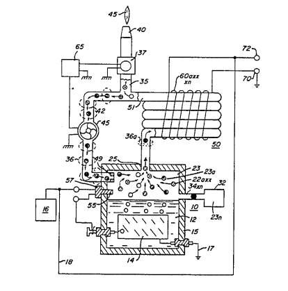 |
|
|
|
|
|
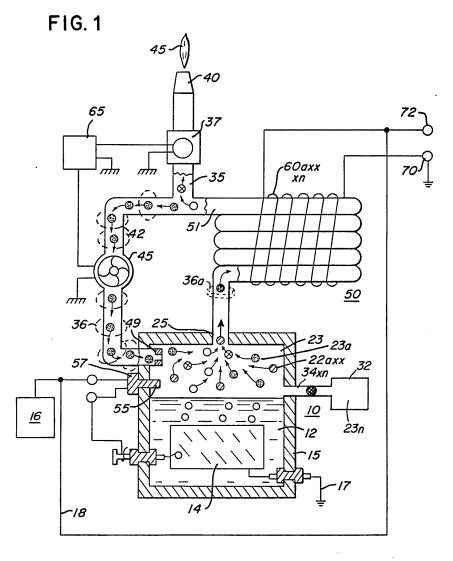
Electrical Pulse Generator #4,613,779
PDF Download: Meyer #4,613,779 Electrical Pulse Generator.pdf
ABSTRACT:
An electrical pulse generator comprising a series of electromagnets spatially positioned about the outer circumference of a disc-like base and a second series of complimentary electromagnets positioned about an inner position on said disc. One of each of said first and second series electromagnets positioned relative to each other creating a magnetic field therebetween. A second disc-like base rotatable above and parallel with said first disc. A continuous coil winding ring mounted on the underside of said second disc and positioned relative to said first and second series of electromagnets to traverse said magnetic field upon rotation of said second disc and thereby inducing a voltage/current potential in said coil winding.
BACKGROUND:
Power supplies for electrical systems have been utilized for a century or so. As time progressed new uses of electrical systems placed a need for more sophisticated systems. One particular utilization is the need for power transfer to the utilization device but yet with the requirement that there be power isolation. The advancement of electronics and power devices such as SCRs, Triacs and the such, appeared to be an obvious solution to such a power transfer. Current limiting circuits also were developed. Unfortunately, the solution was not met. The electronic devices in most instances could not limit or tolerate high power. Finally, it became apparent that the electrical systems, with this type of current limiting requirement necessitated electrical power supplies—not electronic. A very ineffective device is the auto alternator that will provide an increased power output with limited current. However this device, too, with it's sufferings, such as opposing magnetic fields, rubbing contacts and the such, made this device very inefficient.
SUMMARY OF INVENTION:
The electrical generator of the present invention is a substantial improvement of the state of the art in power isolation and power transfer and particularly the conventional alternator. A practical working embodiment has no contacts and no opposing magnetic fields. Also of equal significance is that the voltage output is variably dependent on several controllable features. The structure comprises a series of electromagnets positioned on the outer periphery of a stationary disc. A second series of electromagnets are positioned about the inner circumference of the stationary disc. One of each of said first and second series of electromagnets are positioned relative to one another to create a magnetic field therebetween when energized. A second disc has positioned on its underside a winding coil having a non-magnetic ring with a continuous winding thereon, extending downwardly between said first and second series of electromagnets.
The winding is positioned between the first and second series of electromagnets in the magnetic field created thereby. Upon rotation of the second disc the continuous winding on the ring traverses the magnetic fields and in turn the magnetic fields induce a voltage in the windings on the ring. In a preferred embodiment, a third and fourth series of electromagnets are positioned on the upper side of the rotatable disc much in the same manner as the first and second series of electromagnets positioned on said first stationary disc. The voltage/current induced in said first ring winding is utilized to energize said third and fourth electromagnets to create a second magnetic field therebetween. The second non-magnetic ring traverses the second magnetic field, causing an electrical potential for utilization. The apparatus does not have contact rings or brushes, nor are there opposing magnetic forces. Simi- lar arrangements are cascaded for voltage multiplication. Multiple windings on each ring provide independent outputs for multiple utilization devices.
OBJECTS:
It is a principal object of the present invention to provide an electrical arrangement that is power isolated but yet, permits increased power transfer to a utilization device. Another object of the present invention is to provide such an electrical system that is free of opposing magnetic fields, contacts, slip rings, moving wires, and the like. Another object of the present invention is to provide such an electrical system that has an output potential that may be varied in magnitude. Another object of the present invention is to provide a structure that is not affected in size and that may be duplicated in cascade for high power outputs. Still another object of the present invention is to provide a winding ring having induced therein multiple discrete voltages. Other objects and features will become apparent from a detailed description of the invention when taken in conjunction with the drawings in which:
BRIEF DESCRIPTION OF DRAWINGS:
FIG. 1 is a top view illustrating a first and second series of electromagnets positioned on a first and second metallic base plate in a physical relationship to create a magnetic field therebetween.
FIG. 2 is a schematic illustration of a non-magnetic 30 ring having a secondary winding wound thereon and FIG. 2A illustrates multiple windings with discrete voltage terminals wound on the ring.
FIG. 3 is a cross-sectional view of a complete preferred embodiment.
FIG. 3A is a partial illustration of the systems of claim 3 that have been cascaded.
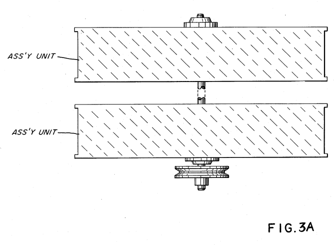
DETAILED DESCRIPTION OF DRAWINGS:
With particular reference now to the drawings and the figures therein, the basic assembly comprising the electrical generator of the present invention includes a stationary disc 10, a first series of electromagnets 15 positioned about the outer periphery 12 of the disc 10, and a second series of electromagnets 13 positioned about the inner periphery 14 of the disc 10. The electromagnets 13a xxx 13n and 15a xxx 15n are positioned end-wise in a face-to-face relationship. The magnetic fields of the electromagnets of the complimentary pairs of electromagnets is created in that each successive magnet 13a xxx 13n in the first series are of opposite polarity, and similarly each magnet 15a xxx 15n in the second series is also of opposite polarity. Again, each of the electromagnets of the first series 13a xxx 13n in the complimentary pairs of electromagnets and of the second series of electromagnets 15a xxx 15n, are of opposite polarity. Upon energization of the first and second series of electromagnets, as set forth below, there is created a magnetic field between each complimentary pair of electromagnets in the first series 13a xxx 13n and 15a xxx 15n, as depicted by field 20. The outer ring 12 coupling the series of electromagnets 15a xxx 15n and the inner ring 14 coupling the series of electromagnets 13a xxx 13n are each of magnetic material. The magnetic field 20 extends through each magnetic; that is, the magnetic rings 12 and 14 magnetically couple the magnetic fields thereby enhancing the magnetic field between each pair of complimentary magnets.
In this way if there are discrepancies in the structures, orientation etc., the inductive coupling rings 12 and 14 of the electromagnets 13 and 15 will integrate and average the magnetic fields. Each magnetic field between the first and second series of electro- magnets are now exactly identical. The significance of having identical fields resides in the induced output voltage, a pulse of identical magnitude. With particular reference to FIG. 2 there is illustrated the winding ring 30 comprising a non-magnetic loop 32 having a conductive wire 35 wound thereon. The number of windings 35 on ring 30 is determined by the desired output at the ring-winding output—within practical limitations. It can be appreciated, the greater the number of turns the greater the induced output voltage at terminals 37. With reference to FIG. 2A there is illustrated the winding ring 30 with more than one winding 35a xxx n thereon. The purpose of windings 35a xxx n as set forth below, is to provide isolated voltage sources for a like number of utilization devices. The loop may be brass for rigidity and reliability. The windings 35 may be copper or other highly conductive metallic wire. In FIG. 3 there is illustrated in a cross-sectional side view, a complete operable preferred embodiment of the present invention. The electromagnets 13a xxx 13n and 15a xxx 15n comprise the outer periphery series of electromagnets and inner circle of electromagnets of FIG. 1.
The electromagnets 15a xxx 15n (only two electromagnets visible), are supported by angle brackets 46a xxx 46n. One end of the bracket 46 supports the electromagnet and the other end is secured to the stationary disc 10. Also secured to disc 10 is a voltage terminal 50 for applying an electrical voltage current potential to each of the electromagnets 13a xxx 13n and 15a xxx 15n. Shown in cross-section in FIG. 3 is the winding ring 30 positioned in the gap between electromagnets 13a xxx n and 15a xxx n. The winding ring 30 is supported by support 31 to the underside of rotating disc 44. Disregarding only for the moment the upper portion of FIG. 3, the fundamental operation of the invention may be described. The electromagnets are positioned end-wise with the inner ring of electromagnets 13a xxx 13n facing the outer ring of electromagnets 15a xxx n. The one magnet will have an end north pole whereas the opposite magnet will be an end south pole. Also, the adjacent magnets will be of opposite polarity.
Upon energizing the electromagnets, via terminal 50, in the gap between electromagnets 13a xxx n and 15a xxx n there will be a magnetic field 20. Considering now that disc 44 is rotating there will be a relative motion between the first and second series of magnets with the winding ring 30 and in consequence the winding ring 30 is traversing the series of magnetic fields 20a xxx n. As the winding ring 30 passes through each of the magnetic fields there will be induced a voltage/current in each of the windings 35a xxx n thereon. The voltage/current potential induced in the windings 35a xxx n will have a magnitude depending on certain parameters and configurations. As aforesaid the greater the number of turns of the winding ring 35, the greater the magnitude of the induced voltage therein. The strength of the magnetic fields 20a xxx 20n will also be proportionably reflected in the output voltage at terminals 37a xxx n. One factor of that the strength of the magnetic field is directly dependent on is the magnitude of input voltage at terminal 50.
Also, the size, configuration and the number of turns on each electromagnet and the number of electromagnets will be directly proportional to strength of the magnetic fields. Finally and perhaps most significantly, is the speed of rotation of the winding ring 30 via rotating disc 44, through the magnetic fields. It can be appreciated an increase in speed results in an increase of speed in tra- versing the magnetic fields 20a xxx n and thereby a greater voltage induced in winding 35. Also relative to the input voltage, wherein the input voltage is a pulse, the pulse repetition rate will be directly proportional to the magnitude of the voltage output. However since the frequency of the output pulses is dependent on the number of magnetic fields, the frequency of the output pulses remain constant. In the embodiment of FIG. 3 the speed of rotation is dependent on the speed of the drive to pully 22. The drive consists of shaft 24 having at its lowermost end pulley 22, secured thereto and positioned thereon by set washer 26. The shaft 24 passes through bearing connected to the stationary disc 18. The intermediate position of the shaft is secured by a set washer 29 and plate washer 23 to the rotating disc 44. The upper end of shaft 25 24 extends through the stationary upper disc 41 with the assistance of bearings 28. The input voltage, the voltage/current applied to the electromagnets via terminal 50, may be either alternating current, or pulsed direct current. The alternating current will have alternate reverse cycles at the output terminal 42.
The direct current will result in a direct current output at terminal 42. Since there is induced in winding 35 of ring 30 a voltage only as it passes through one of the magnetic fields, the output voltage at terminal 42 will be a pulsed direct current. The lower stationary disc 10 and the rotating disc 44 are operable as stated, and with a single magnetic field- /coil winding arrangement there will be a step-up in voltage at the output of terminal 42. Also with the rotating disc 44, the output voltage terminals 42 would necessarily include slip-rings, rotating wires, or the like. With continued reference to FIG. 3, the complete preferred embodiment construction of an embodiment that has no slip-rings, rotating wires, or the like may now be described. In addition to the stationary disc 10 and the rotating disc 44 there is added a second stationary disc 41. The two stationary discs 41 and 10 are maintained in their relative position by stanchions 43 secured at either end to the two discs 10 and 41. On the upper side of the rotating disc 44 there is fixed thereon a third 17a xxx n and fourth 19a xxx n are positioned on the rotating disc 44.
Hence the output of the stationary ring-winding 30 may be readily connected by simple wire 31 as the input to the stationary third 17a xxx n and fourth 19a xxx n series of electromagnets. In the arrangement of FIG. 3 the voltage induced in the ring 30 is not utilized via an output purpose. In this arrangement, the output voltage induced in first coil winding ring 30 is connected via terminal wire 31 to the input to energize the third and fourth series of electro- magnets 17a xxx n and 19a xxx n. It must be appreciated that the ring-winding 30 and the third and fourth series of electromagnets 17a xxx n and 19a xxx n are positioned on the rotating disc 44. Hence the output of the stationary ring-winding 30 may be readily connected by simple wire 31 as the input to the stationary third 17a xxx n and fourth 19a xxx n series of electromagnets.
As aforesaid, there is wound on winding ring 30 and- /or winding ring 40, multiple windings each with its respective output terminals. In certain utilitarian applications there may be multiple devices each requiring its own energization isolated from the other devices. Again, the devices may be of a nature that infinite cur- rent would be drawn; hence, the need for current limiting. In the embodiment of FIG. 3 there are a like number of turns on the winding coils equal to the number of devices. One each output 37a xxx n, at its respective terminal is connected a discrete utilitarian device. In other utilitarian applications, the particular devices may differ in the requirement for voltage and/or cur- rent. Accordingly, the output terminals may be connected in series as shown at 371 or in parallel as shown at 372. In the embodiment of FIG. 3 there is shown output at terminal 42. This terminal is for a single phase output. In those instances, wherein there are multiple phase out-20 puts terminal 52 shall comprise an equal number of voltage terminals. In certain other instances, terminal 52 may comprise a more practical arrangement. That is, winding rings 30 and 40 may comprise a fixed number of windings for 25 instance 15; and similarly terminal 52 will comprise 15 taps—one for each winding.
Then depending on the application up to 15 voltage outputs may be utilized; or alternatively the series or parallel connections can be made at the taps 521 xxx 535. 30 The terminal variable voltage output in its most general aspect denotes an arrangement wherein the output voltage may be increased. As described above, increasing the input voltage, the number of turns, and the strength of the magnetic field will increase the voltage 35 output. In certain other instances, the output voltage is sufficient and there is a need to reduce the output voltage perhaps to zero. One such device is an accelerator wherein the need starts at zero and goes to maximum. 40 In the preferred embodiment, the input voltage is pulsed to reduce the output voltage. A constant D.C. current source will provide maximum output. By pulsing the input to electromagnets the time period of the pulse on relative to number of output pulses is lessened. If the number of input pulses is very small—hence short duty on the voltage of the constant number (frequency does not change) of output pulses will be drastically reduced.
One such practical application would be idling speed of an automobile. With continued reference to FIG. 3 and now FIG. 3A, it can be appreciated any practical number of series of electromagnets and winding rings may be added in cascade for multiple increases in power, Since each complimentary unit is a voltage amplification in itself each additional cascaded arrangement will provide a greater voltage at a geometrical ratio—not arithmetical. In the embodiment of FIG. 3, in the lower portion its electromagnets are fixed and the winding is moved. Whereas in the upper portion the winding is fixed and the electromagnets are moved. It can be appreciated that the essential concern is that there be a relative motion between electromagnets and the winding ring. That which is fixed and that which is moving is irrelevant. Either or both can be moving. Again, discs and rotating discs are shown for simplicity and they are amenable to rotation by a motion drive. It must be understood, other directional movement to obtain the relative motion between electromagnets and windings is within the scope of the invention. As can now be understood there is transferred from a low energy input a high output voltage. But yet, there is power isolation, and current is limited to that of the particular winding. There cannot be a greater current drawn; hence the arrangement is an inherent current limiting voltage source. Significantly, the preferred embodiments do not have opposing magnetic fields or sources, there are no electrical contacting parts, and no restraints. Hence, the input voltage after startup, can be significantly small in comparison to output.
CLAIMS:
1. An electrical generator comprising: a base member, a first series of electromagnets positioned thereon, a second series of electromagnets positioned on said base member in a face-to-face relationship with said first series, each of said first series of electromagnets and its second series complimentary magnets having opposite polarity, and means to energize said first and second series of electromagnets to create a magnetic field therebetween, a non-magnetic ring having windings wound thereon, said ring positioned between said first and second series of electromagnets on a second base member; means for imparting a relative motion between said electromagnets and said ring comprising a rotatable shaft extending through said first base member and connected to said second base member; said motion causing said ring/winding to traverse said magnetic fields between said electromagnets, thereby inducing a voltage/current in said windings; and a pair of terminals on said winding, and means connected to said winding terminals for utilization of said induced voltage/current.
2. The electrical generator of claim 1 wherein said means to energize said electromagnets is an electrical source of alternating current, and wherein the voltage frequent output at said winding terminals is a series of waveforms of like polarity.
3.The electrical generator of claim 1 wherein said means to energize said electromagnet is an electrical source of direct current, and wherein the voltage/cur- rent output at said winding terminals is a series of 50 pulses.
4. The electrical generator of claim 1 wherein said means to energize said electromagnet is a variable electrical source, and wherein; said voltage/current output at said winding terminals 55 is directly proportional in amplitude to said energization input.
5. The electrical generator of claim 1 wherein said magnetic field between said electromagnets is related to the number of turns on said electromagnets. 60
6. The electrical generator of claim 1 wherein said base member is a disc and wherein said first series of electromagnets are positioned in an outer circle and said second series of electromagnets are positioned in an inner circle on said base; wherein said second base member has positioned thereon said winding ring, and means for imparting a relative motion between said first and second base member.
7. The electrical generator of claim 6 wherein said first base member is fixed in position and wherein said second base member is rotatable.
8. The electrical generator of claim 6 further comprising: a third base member fixedly positioned above said rotatable second base member, a third series of electromagnets positioned in an outer circle on said third base member, a fourth series of electromagnets positioned in an inner circle on said third base member in a face to face relationship with said third series of electro- magnets, each of said third series electromagnets and its complimentary fourth series of electromagnets having opposite polarities, and means for connecting said voltage/current from said first ring-winding to energize said third and fourth series of electromagnets to create a magnetic field therebetween; a non-magnetic rings second- ring having windings wound thereon, a pair of terminals on said winding, and said second ring mounted on said third base member and extending said third base member and extending downwardly therefrom in a position between said electromagnets; said second ring-winding, upon rotation of said second base member, traverses said magnetic fields 30 between said third and fourth series of electromagnets, thereby inducing a voltage/current in said windings; and means connected to said second ring-winding terminals for utilization of said induced voltage/current.
9. The electrical generator of claim 8 wherein said third and fourth series of electromagnets has a greater number of turns than that of said first and second series of electromagnets, and wherein said voltage/current at said terminals of said second ring-windings is proportional to the number of turns on said third and fourth windings.
10. The electrical generator of claim 4 wherein said voltage/current at said second ring-winding terminals is directly proportional in amplitude to the amplitude of said voltage/current at said first ring-winding terminals.
11. The electrical generator of claim 7 further comprising pairs of electromagnets in cascade with said first/second and third/fourth series of electromagnets, and wherein said rotatable shaft interconnects said cascaded electromagnets.
12. An electrical generator comprising: a base a first and second series of electromagnets positioned on said , base creating a magnetic field therebetween, a coil winding mounted between said first and second series of electromagnets, means for moving said coil winding relative to said electromagnets comprising a rotatable shaft connected to said base member, said coil winding mounted between said first and second series upon movement traversing said magnetic field and inducing a voltage current therein; and a third and fourth series of electromagnets, a second coil winding positioned therein, wherein said means for moving said coil winding relative to said magnets further comprises moving said third and fourth series of electromagnets relative to said second coil winding, means for utilizing said induced voltage/current in said windings.
13. The electrical generator of claim 12 further comprising, electrical means for energizing said electromagnets and wherein said electrical means is an alternating current.
14. The electrical generator of claim 12 further comprising, electrical means for energizing said electromagnet, and wherein said electrical means is a direct current.
15. The electrical generator of claim 12 wherein said positioning of said first and second electromagnets comprise positioning said first series in an outer circle and said second series in an inner circle; and, wherein said mount for said coil winding is a ring between said first and second series of electromagnets.
16. The electrical generator of claim 12 wherein said means for moving said third and fourth series of electro- magnets further has mounted thereon said first coil winding.
17. The electrical generator of claim 12 further comprising means for connecting said induced voltage/current in said first coil winding to said third and fourth series of electromagnets.
18. The electrical generator of claim 13 further comprising pairs of series of electromagnets in cascade with said first/second and third/fourth series of electromagnets and a coil winding for each of said pairs, and movable means interconnecting each of said pairs of electromagnets for moving each of said coil windings relative to said pairs of windings.
19. The electrical generator of claim 6 wherein said first base member comprises a magnetic outer ring and an inner ring member, said outer ring member interconnecting said first series of electromagnets and said inner ring member interconnecting said second series of electromagnets. 20. The electrical generator of claim 12 wherein said direct current is a pulse direct current, and means for 55 varying said direct current to reduce the voltage output of said winding.
Gas Generator Voltage Control Circuit #4,798,661
United States Patent 15) Meyer 4,798,661 Jan. 17, 1989
[54] GAS GENERATOR VOLTAGE CONTROL CIRCUIT
[76] Inventor: Stanley A. Meyer, 3792 Broadway Blvd., Grove City, Ohio 43123
[21] Appl. No.: 715,749 [22] Filed: Mar. 25, 1985 [51] Int. Cl. . » C25B 9/04; C25B 15/02
[52] U.S. CL. ..... 204/228; 204/278; 204/DIG, 9 (58] Field of Search ......... 204/228, 278, 129, DIG. 8, 204/DIG. 9, 225
[56] References Cited U.S. PATENT DOCUMENTS 3,954,592 5/1976 Horvath .. . 204/129 X 4,184,931 1/1980 « 204/129 4,233,132 11/1980 . 204/228 K 4,316,787 2/1982 204/228 X 4,394,230 7/1983 . 204/228 X 4,424,105 1/1984 ever 204/228 4,457,221 7/1984 204/DIG. 8 4,457,816 7/1984 Galluzzo .. wees 204/129 X
OTHER PUBLICATIONS
Scientific American, Feb. 1987, “The Amateur Scientist,” pp. 134-138, Jearl Walker, author.
Primary Examiner—Donald R. Valentine Attorney, Agent, or Firm—Porter, Wright, Morris & Arthur
ABSTRACT
A power supply in a system utilizing as a source of fuel a generator for separating hydrogen and oxygen gasses from natural water and having the capabilities to control the production of gasses by varying the amplitude of the voltage and/or the pulse repetition rate of the voltage pulses applied to a pair of plate exciters in a vessel of natural water, comprising a sequence of circuitry operative to limit the current of a d.c. potential to a minimum value relative to the magnitude of the voltage applied to the plate exciters.
The circuits each function up to a given magnitude of voltage to inhibit and curtail the flow of electrons from the plate exciter having the negative voltage potential applied thereto.
The first circuit operative from a first magnitude of voltage comprises converting the voltage potential applied to the plate exciters to a uni-polar pulse voltage d.c. of a repetitive frequency.
The next circuit varies the duty cycle of the uni-polar pulse voltage d.c.;
followed by rearranging the application of the voltage to the exciters to individual exciters each having the voltage applied thereto independently of the other plate exciters in the generator.
The next circuit comprises an electron inhibitor that prevents the flow of electrons; the circuit being in the terminal line between the negative plate exciter and ground.
In those applications of the generator wherein excessively high voltage is to be applied to the plate exciters for a very high yield of gasses, a second electron inhibitor of a unique structure is serially connected with the first electron inhibitor.
The second named inhibitor having a relatively fixed value and the first inhibitor connected in series is variable to fine tune the circuits to eliminate current flow.
Figures 2 - 8
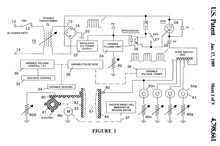 |
||
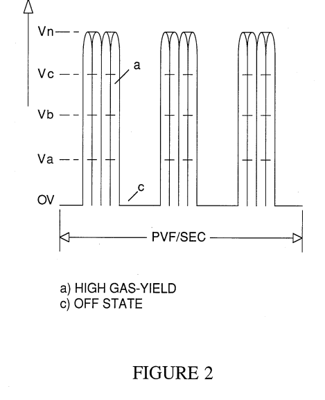 |
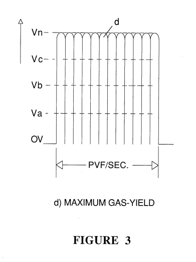 |
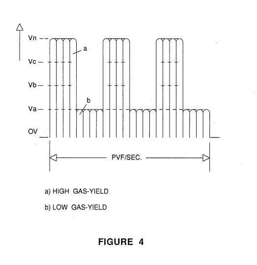 |
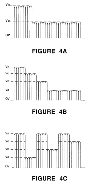 |
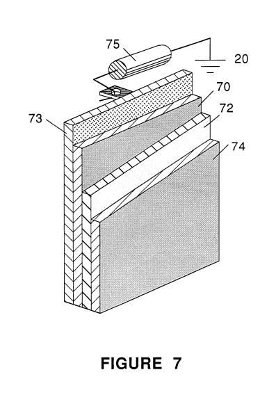 |
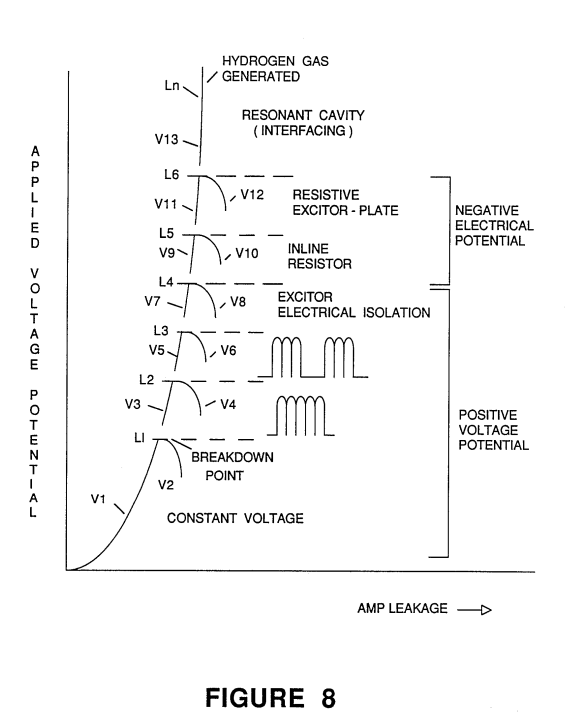 |
GAS GENERATOR VOLTAGE CONTROL CIRCUIT
BACKGROUND AND CROSS REFERENCES
The phenomena of physics was discovered that the hydrogen atoms in the water molecule will take on a positive charge whereas the oxygen atom in the water molecule takes on a negative charge when the water molecule is exposed to an electrical voltage. The two hydrogen positive charged atoms and the one oxygen negative charged atoms, in magnitude, are in a state of equilibrium .
In my co-pending patent application, Ser. No. 302,807, now abandoned for Hydrogen Generator, the above noted principle of polarization is utilized.
The simultaneous application of a positive voltage pulse to one plate exciter and a negative polarized voltage pulse to the other plate exciter in a vessel of natural water, will form polarized voltage electrical zones around the plates of a respective polarity.
The positive voltage plate exciter zone attracts the negative charged atoms of the water molecule and the negative voltage plate exciter zone attracts the positive charged hydrogen atoms of the water molecule.
The opposing attractive forces causes the hydrogen and oxygen atoms to disassociate from the water molecule; and thereby, release the hydrogen and oxygen gasses.
In that natural water is utilized in the generator and that natural water contains a considerable percentage of ambient air, ambient air gas will also be released similarly to the oxygen and hydrogen gasses from the water molecule.
The above described process is apparently not a chemical reaction process such as in Faraday’s Laws.In that process electrolyte is added to distilled water to draw current. The reaction of the electrolyte with that of the corrosive electrodes releases the hydrogen and oxygen gasses.
Characteristically, Faraday’s Laws requires:
“The rate of decomposition of an electrolyte is dependent on current and independent of voltage. xxx will depend on current regardless of voltage, provided the voltage exceeds a minimum for a potential.”
In the voltage dependent/current restricted process of my co-pending patent application, the disassociation of the hydrogen and oxygen atoms from the water molecule, is attributed to the physical force attraction of the polarized zones adjacent the plate exciters on the charged hydrogen and oxygen atoms having a polarity opposite to that of the polarized zone.
This physical force is exemplified in my co-pending patent application, Ser. No. 422,594, filed Sept. 24, 1982, now abandoned for Hydrogen Generator Resonant Cavity, wherein the principle of physics that physical motion of an element between spatially positioned structures will resonate if the distance between the structures, in wavelengths, is matched to the frequency of the force causing the physical motion, is utilized in a practical and useful embodiment. The dc voltage - with current restricted, applied to the pair of plate exciters spatially positioned in a vessel of natural water, is pulsed. The pulsing voltage on the plate exciters applying a physical force is matched in repetition rate to the wavelength of the spacing of the plate exciters. The physical motion of the hydrogen and oxygen charged atoms being attracted to the opposite polarity zones will go into resonance. The self sustaining resonant motion of the hydrogen and oxygen atoms of the water molecule greatly enhances their disassociation from the water molecule.
In my co-pending patent application, Ser. No. 411,977, filed Aug. 25, 1982, for Controlled Hydrogen Gas Flame, the gasses separated from the water, the hydrogen and oxygen together with the ambient air non-combustible gasses, are mixed as they are released by the generator. The mixture of gasses are collected in a pressure chamber in the generator and thereafter expelled through a nozzle having a port configuration with openings dependent on the mixture of gasses. The nozzle is connected directly to the collection chamber and ignited.
The gas mixture has a reduced velocity and temperature of the burning flame from that which would occur solely with a hydrogen and oxygen mixture. To further control the flame, there is added to the mixture other non-combustible gasses in a controlled amount. Accordingly, the nozzle ports is related to the temperature and velocity of the flame. The several ports will accommodate flames of greater size without the danger of flashback or blowout such as would happen with a single flame.
This physical force is further demonstrated in the plate separation phenomena of the first aforementioned co-pending patent application. Simply, the closer the spacing between the plate exciters the greater the attractive force of the opposite polarity plate exciters on the charged hydrogen and oxygen atoms of the water molecule. With a given spacing, an increase in the magnitude of the voltage applied to the plate exciters will result in an increase in the rate of production of the gasses. With a voltage of a fixed amplitude a variation in the plate exciter spacing will affect the rate of production of the gasses. An increase in the spacing will result in less generation, whereas a decrease in the spacing of the plate exciters will result in an increase in gasses.
THEORETICAL ANALYSIS
The electrical phenomena of a positive potential voltage applied to one plate exciter and the application of a negative voltage potential applied to another plate exciter positioned in a vessel of water, may now be considered,
Distilled water, like air, having no conductive medium, will inherently inhibit electron leakage. The magnitude of the applied voltage to the pair of plate exciters is correlated with the physical force on the electron movement. The magnitude of the initial force and the magnitude of the force to leak the electrons, and there- after cause current flow, may be calculated or more readily empirically determined.
A small amplitude negative voltage applied to the negative plate exciter, will cause a physical disturbance to the movement of the floating electrons. However, the small amplitude voltage is insufficient to cause the electrons to leak and enter the attractive field force area of the positive plate. As the magnitude of the applied voltage is increased, the disturbance to the movement of the electrons is increased. With a further increase in the amplitude of the voltage applied to the plate exciters—to a limiting level, the resistance of the medium to the attractive force of the opposite polarity exciter plate on the electron leakage will be overcome.
As the electron leakage enhances, the flow of the electrons to the positive plate exciter gradually increases as they enter the attractive field of the positive plate. Upon attaining a heavy flow of electrons reaching the positive plate attractive area, arcing will occur. An electrical arc is formed between the two plate exciters. When this occurs a direct short conductive flow of current will flow across the plates.
The electrical arc between the pair of plate exciters will form a direct line of conductivity; current will flow unrestricted. Upon the electron leakage attaining a direct short, the current is at a maximum. The voltage being subjected to the current takeover decreases gradually upon initial electron leakage and thereafter drops as the flow of electrons increases. When the electron leakage arcs over to the positive potential plate exciter, the voltage will drop to zero.
As stated above, the spacing between the pair of plate exciters in a vessel of water having a d.c. voltage applied, is correlated with the gas production rate. The closer the spacing between the pair of plate exciters, the greater the yield of gas generated. If the spacing of the pair of plate exciters is altered to a minimum spacing level, the attractive force of the positive polarity plate will overcome the resistance of the water medium. Electron leakage will occur and from gradually to rapidly increase until arcing between the pair of plate exciters forms a direct path and consequently a direct short.
The distance between the plates and the amplitude of the voltage applied, each independently affect the other. The two variable factors are interrelated; the one being variable relative to the other. The spacing being inversely proportional to the amplitude of the voltage.
SUMMARY OF THE INVENTION
In the utilization of a generator for the separation of the hydrogen and oxygen gasses from water; and wherein the production of the gasses is varied by varying the amplitude of the voltage and/or the pulse rate -- duty cycle of the pulsed d.c. voltage applied to the plate exciters in a vessel of water: the present invention comprises a power supply with the applied voltage to the pair of plate exciters variable from zero upward to extremely high voltages; but yet, that inhibits the electron leakage.
The power supply of the present invention includes circuitry for an increased production of the generation of the gasses through varying the amplitude of the voltage applied to the plate exciters. The circuitry includes means and components for restriction of the electron leakage (current flow).
The applied voltage to the pair of plate exciters is a uni-polar pulse d.c. voltage of a repetitive frequency. Alternate power circuitry is utilized. In the first embodiment the input voltage is alternating current fed to a bridge rectifier; whereas in the second preferred embodiment, the input voltage is direct current applied to the primary of a rotating field secondary winding.
With a very low level of amplitude of the voltage applied to the plate exciters, no electron leakage from the negative potential plate exciter to the positive potential attractive field will occur. An amplitude of the voltage above a first forceful level will cause electron leakage. The circuitry of the invention overcomes the electron leakage with the application to the plate exciters the aforesaid pulsed d.c. voltage.
An increase in amplitude of the applied voltage above a second level, will result in electron leakage.
To obtain additional gas production without electron leakage, circuitry in the power supply prevents electron leakage by varying the duty cycle of the pulsed d.c.voltage applied to the plate exciters. The varying levels of amplitude.of the duty cycle pulses effectively restrains the electrons from the B+ attractive field.
The pulsating d.c. voltage and the duty cycle pulses have a maximum amplitude of the level that would cause electron leakage. Varying of the amplitude to an amplitude of maximum level to an amplitude below the maximum level of the pulses, provide an average amplitude below the maximum limit; but with the force of the maximum limit.
In most instances of a practical application of the hydrogen and oxygen generator the pair of plate exciters will be several pairs connected in parallel. There will be one terminal to the positive voltage and another terminal to the negative voltage. A further expediency to eliminate electron leakage is attained by eliminating the large surface area probability of stray electrons.
It is noted that the first two circuit components and the multiple connections for restricting electron leakage relates to the plate exciter having the negative voltage applied thereto. That is the circuitry overcomes the attractive force of the B+ potential field. Additional circuitry is provided for very high yield gas production above the aforesaid upper limits, in the negative applied voltage plate exciter.
A circuit is included in the negative plate exciter that practically eliminates electron flow; that is, the electrons are prevented from reaching the negative plate exciter and thereby eliminating the affect of the attractive force of the B+ field. A current limiting resister connected between the negative plate exciter and ground, prevents current flow -- electron leakage to the the opposite polarity field.
The circuit comprises a limiter resistor connected between the negative plate and ground that blocks current flow -- electron leakage to the negative plate. The practical elimination of the current has no affect on the voltage, in the preferred embodiment, since there is no voltage drop.
In a sophisticated embodiment, the limiting resistor comprises a unique structure of poorly conductive material having a resistive mixture sandwiched therebetween.
A second resistor of the variable type is serially connected to the unique limiter for tuning. The value of the limiting resistance is determined by the current passing there through. The variable is employed until the ammeter reads zero or close to zero as possible.
The sandwich type limiter is varied in value by controlling the mixture of resistive material to binder.
The circuitry and expedients to inhibit the electron leakage at all levels of the magnitude of the voltage applied to the plate exciters is sequence of steps and functions operable from predetermined circuit components. The order of the circuit functions is set and preferably not altered; however, each of the specific variables can be varied independently and varied with inter-related function to the other.
The phenomena that the spacing between two objects is related to the wavelength of a physical motion between the two objects is utilized herein.
A relatively small increase in amplitude will yield an output several magnitudes greater when the motion of the water molecule is moving to and fro with a repetition rate to match the resonant length of the spacing between the pair of exciters.
OBJECTS OF THE INVENTION
It is a principle object of the present invention to provide a power supply for a hydrogen and oxygen gas generator wherein varying the voltage amplitude varies the rate of generation of the gasses generated.
Another object of the present invention is to provide such a power supply that includes circuitry to permit voltage to be varied in amplitude with current restricted to a minimum relative to the amplitude of the voltage.
A further object of the present invention is to provide such a power supply for a hydrogen and oxygen genera- tor wherein the electron leakage between the plate exciters is inhibited.
A further object of the present invention is to provide a power supply for a hydrogen and oxygen generator including circuitry for a uni-polar pulse d.c. voltage of a repetitive frequency from either an alternating or a direct current input.
Still another object of the present invention is to provide a power supply having varying levels of voltage indicative of varying levels of gas generation that is programmable with a utilitarian device, particularly, when the generator has exciters spaced a distance in wavelength matched by the voltage pulse frequency.
Further objects and features of the present invention will become apparent from the following detailed description when taken in conjunction with the drawings in which:
BRIEF DESCRIPTION OF DRAWINGS
FIG. 1 is an overall illustration of the present invention in a preferred embodiment; the components shown partly in block schematic and partly pictorially.
FIG. 2 is a first waveform illustrating the uni-polar pulse d.c voltage of repetitive frequency with a uniform duty cycle.
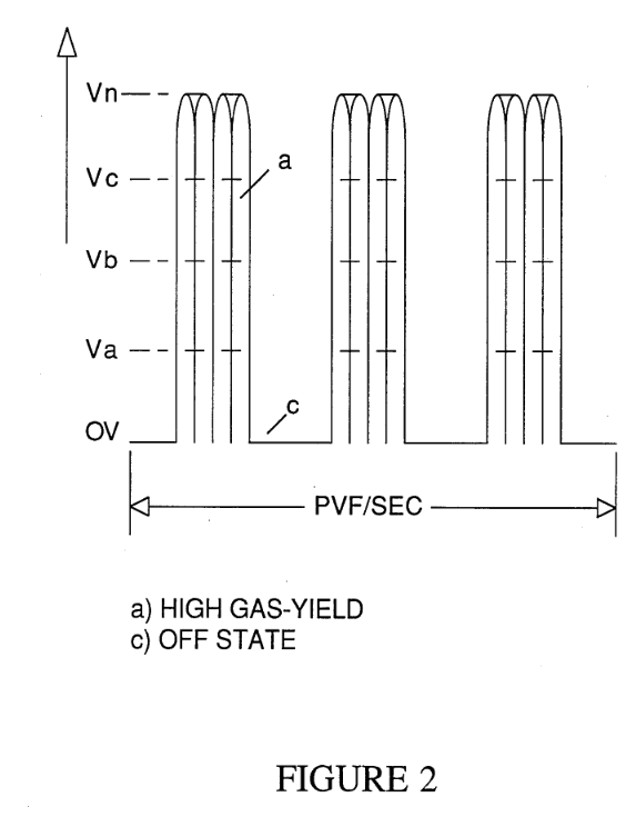 |
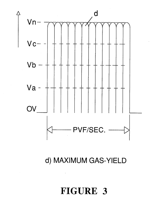 |
FIG. 3 illustrates the uni-polar pulse voltage with a continuous repetitive frequency.
FIG. 4 illustrates the uni-polar pulse voltage of a repetitive frequency having a uniform duty cycle from a low gradient level to high gradient level;
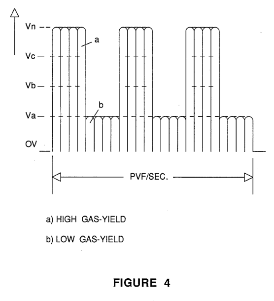
FIG. 4A illustrates the duty cycle as being non-uniform and between gradient levels;
FIG. 4B illustrates the duty cycle comprising varying gradient levels and of non-uniform repetition; and
FIG. 4C illustrates the varying gradient levels as being uniform.
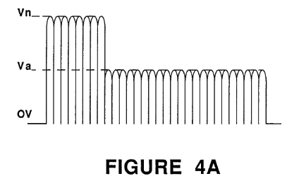 |
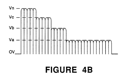 |
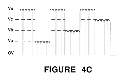 |
FIG. 5 illustrates partly schematic and partly in block the pulse frequency generator from a direct current voltage source.
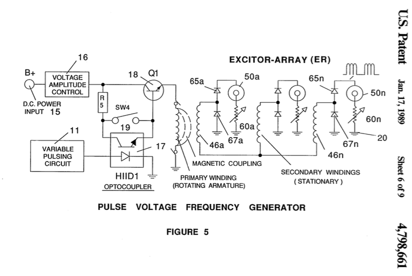
FIG. 6 is a schematic of the circuitry for programming the varying levels of voltage to practical applications.
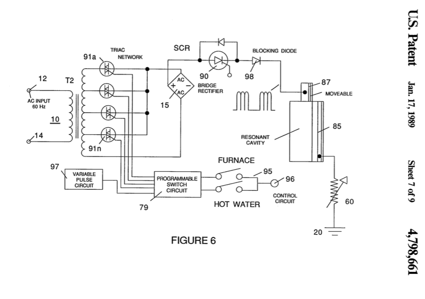
FIG. 7 is a cross-sectional perspective of a multiple layer sandwich resistive element for inhibiting electron leakage.
FIG. 8 is a graphical illustration of the varying limitations of voltage amplitude for inhibiting electron leakage.
DETAILED DESCRIPTION OF THE INVENTION
Referring to the drawings and in particular to FIG. 1, there is illustrated the present invention in its preferred embodiment of a power supply for the aforementioned hydrogen and oxygen gas generator, providing variable amplitude voltage with inhibited electron leakage.
The alternating current rectifier circuit 10 comprises input alternating current terminals 12 and 14. Switch 13 is a typical on/off switch. Transformer 10 is an inductive primary and secondary transformer connected to a bridge rectifier 15. The inductive field 11 of the transformer 10 is variable in a known manner to yield a variable frequency alternating voltage/current to the primary winding.
The bridge 15 arms are connected across the input of the secondary winding of the transformer 10. The upper and lower arms are connected across the extreme ends of the secondary winding and the left hand arm is connected to the output of the rectifier 15. The right arm is connected to ground 20. The rectifier inverts the negative swing of the alternating current and thereby results in an output voltage pulse of a frequency twice that of the input frequency of the alternating current voltage applied to the terminals 12 and 14.
It is appreciated that if the alternating current voltage is varied in frequency by the variable inductive field 11, the output frequency across the bridge 15 will still be twice the frequency of the alternating voltage across the secondary of the transformer secondary winding 10.
As noted in the aforesaid co-pending patent application, the rate of generation of the gasses is directly related to the amplitude of the applied voltage to the pair of plate exciters.
The power supply of FIG. 1 includes a variable circuit 30 for varying the amplitude of the rectified voltage by rectifier 15. The variable voltage circuit , in turn, is directly controlled by the gas rate function separately, sequential, and together with the phenomena of a resonant cavity.
The waveform output of the bridge is shown as a uni-polar d.c. voltage pulse of a repetitive frequency (hereinafter referred to as a d.c. voltage). It is noted that the pulse voltage is not filtered and the plate effect is utilized.
As stated, a voltage with an amplitude below the minimum level for example, with a given size apparatus, 2.5 volts (L-1 of FIG. 8) when applied to the pair of plate exciters, is insufficient amplitude to force the electrons to leak from the negative plate exciter. The hydrogen and oxygen gasses will be separated from the water at the low level of voltage amplitude; and the gasses generated will also be at the minimum.
Above the minimum level (L-1 of FIG. 8) of amplitude, the applied voltage will have a sufficient force to agitate and cause movement of the electrons around the negative plate exciter. As a consequence electron leakage would take place.
To overcome the forceful effect on the electrons around the negative plate exciter, but apply a voltage of increased amplitude for an increase in gas production, the first step in a sequence is utilized. The pulsed d.c. voltage having a frequency predetermined by the input alternating current to the transformer 10, is applied to the plate exciter.
The maximum amplitude of the d.c. voltage pulse is sufficient to cause an increase in gas production; however, the minimum amplitude of the pulsed d.c. voltage is insufficient to cause electron leakage. The average of the maximum and the minimum results in an increase gas output but without electron leakage.
The physical force on the movement of the electrons around the negative plate exciter is further controlled in specific situations by varying the frequency of the pulsed d.c. voltage.
The frequency of the pulsed d.c. voltage may be altered by an alternating current of another frequency applied to the input terminals 12 and 14. Alternatively, the frequency of the pulsed d.c. voltage may be varied as shown by the variable transformer 10 winding 11.
With reference to FIG. 3, the uni-polar pulsed d.c. voltage of a constant frequency is illustrated.
In the first mentioned variation of the amplitude of the pulsed voltage, there is further shown in FIG. 3 voltage levels from OV, Va xxx Vn.
As noted below a variation of amplitude above the predetermined levels will permit electron leakage.
Referring to FIG. 8, there is illustrated an appreciation of the significance of electron leakage.
Initially it is to be noted that the first amplitude level, L-1, is when electron leakage occurs.
Prior to leakage, voltage V1 increases on demand.
At the level L-1, when leakage occurs, current begins to flow and as a consequence the voltage Vz begins to drop.
The current flow increase is proportional to the voltage decrease; and upon arcing, a dead short condition for current takeover, the voltage V2 drops to zero.
The same rise and fall in amplitude of the voltage versus current flow repeats at amplitude levels L-2. L-3, L-4, and L-5; again, in a given size apparatus, voltages of 4, 5.5, 7, and 8.5.
It is seen then, that it is paramount that electron leakage must be curtailed when the operation of the system is dependent on voltage, such as the generator utilized herein.
Returning to the overall circuit of FIG. 1, the uni-polar pulsating d.c. voltage is an improvement in raising the amplitude of the voltage without electron leakage. Unfortunately, it too, has a voltage amplitude limit of 4.0 volts as shown by L-2 of FIG. 8.
To further restrict current flow with amplitude voltages above the level L-2 of FIG. 8, electron leakage is inhibited from the exciter plate having the negative voltage applied thereto, by varying the duty cycle pulse of the pulsed d.c. voltages as shown FIGS. 2, 3, and 8.
|
|
In an initial application the pulsed d.c. voltage is switched on and off for equal periods of time.
With reference again to FIG. 1, the variable pulsing circuit comprises an electronic switch SCR 28 operable from one state to another form the opto-coupler timing circuit 26. The operation and of the pulsing of a voltage is within the state of the art.
Diode 29, a blocking diode, is operable in the accepted manner.to eliminate stray electrons, shorts, variances, spurious signals, and the like. In addition the diode 29 blocks the back-electromagnetic force.
The pulsing of the pulsed d.c. voltage, as shown by the waveform of FIG. 2, comprises switching, via trig- ger circuit 26, the pulsed d.c. voltage on an off—in a first instance. As will be understood below relative to the programming circuit of FIG. 6, the time period of the pulses may be varied periodically or apericdically, the duration of the on/off period may be varied, the gradient level of the on/off pulses may be varied, and all of the above may be interrelated into a sequence of duty pulses with the varying conditions all as shown in FIGS. 4, 4A, 4B, and 4C.
The duty pulses are effective much in the same manner as the pulsed d.c. voltage pulses in the function of inhibiting electron leakage. The “second” series of force on the electrons around the plate exciter, having the negative potential voltage applied, in terms of voltage amplitude is greater. However, the greater amplitude is averaged by the double pulses to an effective voltage of an amplitude to inhibit electron leakage.
As previously stated, the voltage pulses applied to the plate exciters further enhance the rate of generation of the gasses. Accordingly, to achieve the most effective relationship between gas generation and current limiting, the voltage amplitude is interrelated to the pulse repetition rate of the duty pulses in FIG. 1. Also, the rate of production is related to the frequency of the uni-polar d.c. voltage, the frequency then should be interrelated to the duty cycle pulses.
With continued reference to FIG. i, mechanical switch 40 is a known means for applying the voltages to the plate exciters individually and sequentially. The negative plate exciter is the center conductor of an inner and outer arrangement. The negative plate exciter is connected to ground 20; ground 20 being the power supply ground.
The dual pulses comprised of the frequency repetitive pulses and the duty cycle pulses similarly to the previous configuration. The amplitude is effective to increase the output gas generation with an upper limit of 5.5 volts, in this instance L-3 of FIG. 8.
In a typical configuration of the hydrogen generator of the aforementioned co-pending application, the plate exciters will comprise a plurality of pairs. In the previous configurations the positive voltage was applied in parallel to all the inner plates; whereas the negative voltage was applied to all of the inner plate exciters in parallel. It has been found that an increased surface between the inner and the outer plates will increase the probability of an electron breaking free and leaking to the attractive field of the positive voltage plate. The surface leakage has been eliminated by applying separately and individually the positive voltage to each of the outer plate exciters and the negative voltage to each of the inner plate exciters.
With reference to FIG. 8 again, it is seen that although the serially connected exciter plates do permit a higher amplitude of voltage to be applied, it too, has a limitation L-4 of 7 volts.
The next expediency in the sequence for inhibiting electron leakage is the current inhibitor resister 60 as shown in FIGS. 1 and 5. The circuit 60 comprises a simple resistor of the commercial type or specially made for the particular application. The resistor is variable to provide fine tuning of the electron inhibiting. In that the each pair of plate exciters are connected separately, a resistor 60¢ xxx 60n is connected to each of the plates having the negative voltage connected thereto. In this embodiment the inner plate of the exciters 50¢ xxx 507. In. that the inner plate had been normally connected to ground, the resistive element is now connected between the inner plate and ground.
As known in electrical art the resistor will provide a complete block to electron leakage—current flow. However, since the resistor 60 is connected from ground-to-ground there is no real affect on the voltage; and since there is no connection with the positive side there is no voltage drop.
The electron leakage resistor will again raise the upper limit of 8.5 volts amplitude before breakdown as shown at L-5 of FIG. 8. In the generation of the hydro- gen and oxygen gasses to an infinite limit, as yet not fully appreciated, the upper level of amplitude of the voltage is removed with the utilization of the electron inhibitor of FIG. 7.
In this embodiment of the current inhibitor connected to the inner plate having the negative voltage applied thereto, comprises a stainless steel sandwich 70/74 with a resistive material therebetween. The stainless steel is a poor conductive material and hence will restrict to some extent the electron flow. Other poor conductive material may be utilized in lieu of the stainless steel. The electron inhibitor 70/74 is connected in the same manner as resistor 60—between the inner plate having the negative potential connected to it and ground.
The resistive value of the electron inhibitor 70/74 is chosen empirically to a closest value, thereafter the total value of the resistance is fine tuned by the resistor 75 connected serially between the inner plate and ground.
To alter the resistive value of the electron inhibitor 70/74, the resistive material 72 comprising a mixture with a binder is altered in the percentage of resistive material to binder.
With reference to FIGS. 1 and 8, the pulse d.c. volt- age of a repetitive frequency and the duty cycle pulses, together with the serially connected plate exciter techniques in the sequence for limiting the electron leakage is in relation to the positive exciter outer plate. The current inhibitor resistor 60 and the current inhibitor resistor 70/74 are in the negative voltage line connected to the inner plate.
|
|
With particular reference now to FIG. 5, there is illustrated an alternative embodiment for deriving the uni-polar d.c. voltage pulse of a repetitive frequency—similar to that of FIG. 1. The distinction in the embodiment of FIG. 5 is that the input voltage is a direct current in contrast to the alternating current of FIG. 1.
In operation of the circuit of FIG. 5, a low voltage, such as from a battery, is applied to the primary wind- ing to the circuit of a rotating field. The primary wind- ing 42 being the rotating field has it opposite end connected to ground. As the field of the primary winding 42 rotates, there is induced three pulses at the output of each of the three secondary windings 46a 468, and 46c.
The repetition of the triple pulse is once per each revolution; hence the number of pulses per given period of time is related to the speed of rotation of the rotating field. A faster rotation will produce a greater voltage frequency. An increase in the number of secondary windings will result in an appropriate increase in the number of pulses; whereas an increase in the number of turns on the secondary windings will increase the amplitude of the pulses. The alternating voltage output of the three secondary windings is converted into pulses by the conventional diode rectifiers 65/67 bridge circuit for each of the separate pairs of exciter plates 50a-50n. In this way a constant uni-polar pulsating d.c. voltage of a repetitive frequency similar to that of FIG. 3 is applied to each of the exciter plates 50a xxx 50”. The output is similar to that derived from the alternating voltage input of FIG. 1. The d.c. voltage is a constant voltage pulse.
Again similar to FIG. 1, there is provided a timed pulsing circuit comprised of a timer 17, switch 19, and transistor 18. Initially, the d.c. pulse voltage is switched on and off, to provide a constant share time duty cycle to the primary winding 42 of the rotating field. In the off period there will be no voltage on the primary winding 42, and hence, no voltage output on the secondary winding 46.
The circuit of FIG. 5 is especially economical in that extremely low amplitude voltages (0-5 volts) is applied to the primary 42. At this low level, the current is negligible and power consumption is minimum. The output voltages from the secondary windings 46 is relatively high and is in the order of two hundred volts. The output voltages from the secondary windings 46 are variable in amplitude by the resistor 16 in the input circuit. A very small increment of input voltage results in a much greater output.
The sequence of circuitry of the pulsed d.c. voltage, duty cycle pulses, serially connected exciters, resistor in the ground line, and the plate resistor are each, and together, effective to eliminate electron leakage. The conditions set forth, in each instance were under actual conditions—with distilled water.
In the basic process of water separation as herein utilized, the hydrogen and oxygen gasses are separated by the application of a voltage to the plate exciters with the attendant current as close to zero as possible. Accordingly, the use of natural water having contaminants is equally operable; the contaminants will have no affect upon the separation of the hydrogen and oxygen atoms from the water molecule; nor will the contaminants have an affect on the plate exciters such as fouling up.
With the use of certain natural waters particularly sea water with a salt content or natural water with an iron or other mineral content, the natural water would have a tendency to draw current. The passing of current as set forth above, would cause the voltage to drop and basically would curtail the operation of the generator.
The resistor 60 of FIGS. 1 and 5, connected between the exciter plate having the negative voltage applied thereto and ground is an effective current limiter/electron inhibitor. In simple terms the restriction to current flow to the negative plate is a restriction to the flow of current between the pair of plate exciters.
There can be no electron leakage from the negative potential plate exciter if there are no electrons to leak.
The resistor 60 of FIGS. 1 and 5, and especially when taken together with the resistive plate structure of FIG. 7, current is eliminated from the plate exciters.
In FIG. 1 there is illustrated an alternative manner of varying the rate of separation of the hydrogen and oxygen gasses from water. As fully disclosed and described in the aforesaid co-pending application Ser. No. 302,807, the spacing between the plate exciters in water is directly related to the rate of separation of the hydrogen and oxygen gasses.
The plate exciters 82 and 83 positioned in water 61 are varied in spacing by the rack 80 and gear 81. The variations can be manually or through the programmer 69 for predetermined gas rate generation. The programmer actuates line 37 to the motor 33 to drive the gear 81.
The closer the spacing the greater the gas yield, i.e., the attractive force of the electrical voltage zones is related to spacing. However as noted above, the closer the spacing the greater the probability of spurious electron leakage. It is appreciated the optimum is the closest spacing for gas generation with a minimum of current leakage.
The pulsed d.c. voltage, the duty cycle pulses, the resistor from negative to ground, the serial connections of the exciters, and the plate resistor in series with a variable resistor between the negative plate and ground, is a sequence of circuits that counteract the electron leakage with increased voltage. Similarly, the same sequence individually and in combination are equally applicable with respect to the variation of plate spacing to vary the rate of generation of the gasses but yet, to restrict electron leakage. The voltage. levels from 0 volts upward will be dependent on the physical parameters of the apparatus. In one typical structure of the apparatus the voltage was varied from zero (0) volts to 45 volts. In a smaller structure, the voltage levels of FIG. 8 were utilized.
With reference again to FIGS. 2, 3, 4, 4A, 4B, 4C, and 4D, the waveforms illustrated therein depict the several variations of the pulsed d.c. voltage relative to the duty cycle pulses. Initially, each of the two set of pulses are varied individually. The on/off time of the two sets of pulses in a first instance is uniform. Then the timing of one or the other is varied; the gradient levels of the voltages are varied periodically and aperiodically, pulse duration is varied equally and unequally.
To attain the optimum gas generation with minimum electron leakage, is determined empirically with a gas flow meter and an ammeter. The variables are interrelated but not necessarily having the effect on either gas production or electron leakage. Practical training reduces the tune-up period.
In FIG. 6, there is illustrated the resonate cavity of my aforesaid co-pending patent application Ser. No. 422,594. The resonant cavity described and disclosed therein, is a result of the discovery that when the distance between two stationary bodies is equal in wave- length to the frequency of the movement of an object going back and forth therebetween, the movement of the object will go into resonance. The motion is greatly enhanced and with a repetitive sustained force. The principle applied to the hydrogen and oxygen gas generator of the present invention results in the movement of the water molecules and the atoms to an attractive field will be greatly enhanced when the frequency of the back and forth movement is matched to the wavelength of the distance between the pair of plate exciters.
The amplitude is increased to the minimum for resonance. The voltage amplitude thereafter is maintained at the minimum and raised from the minimum for an increase in gas generation. The minimum is the lower gradient level illustrated in the waveforms of the figures. Since resonance is a matter of matching a physical distance with frequency of the back and forth motion over that distance, matching the particular frequency to the particular wavelength, can be with either d.c. voltage pulses or the duty cycle pulses.
The resonant cavity is depicted in FIG. 4 pictorially. It is understood that the exciter plates 50a-50n of FIG. 1 become resonant cavities by matching the distance between the exciters to a pulse frequency of the same wavelength,
|
|
In FIG. 4 and 4C, the duty cycle pulses are matched in pulse repetition rate to the plate distance.
|
|
In FIG. 4A and 4B, the frequency of the pulsed d.c. voltage is matched to the distance in wavelengths of the plate exciters.
With the frequency of one of the set of pulses matched to the resonant wavelength, the frequency of the other set of pulses is varied to further control the electron leakage and/or to vary the rate of generation of the gasses.
Referring again to FIG. 6, attention is directed to the resonant cavity depicted therein pictorially. The resonant cavity would be the plate exciter of FIG. 1 or any other plate exciter wherein the frequency of the pulses of the applied voltage is matched in wavelength to the distance between the exciter plates
The SCR diode is a duty cycle pulse former much in the same manner as the pulse former 27 of FIG. 1 - The SCR diode 90 is operational in a conventional manner and the diode 91 is a conventional blocking diode. The operation and function of the resonant cavity is much in the same manner as that of FIG. 1 plate exciters 50a-50n.
In a Hydrogen Resonant Cavity Furnace, the pulse repetition rate is matched to the wavelength distance between the two exciter plates to maximize the rate of generation to voltage amplitude. The flame is pulsed from a first gradient level to a lower gradient level—but not off. The lower gradient level is sufficient to maintain at all times the amplitude to sustain resonance.
The waveform is shown in FIG. 4. The lower level amplitude Va is not 0V the zero level; the amplitude level Va is sufficient to maintain resonance with a matched repetition rate of the duty cycle pulses.
In FIG. 6, the programmable switch circuit 79 is for variable inputs to a utilitarian device, such as the aforesaid furnace or the automobile hydrogen engine dis- closed and claimed in my co-pending patent application Ser. No. 478,207. In the practical working embodiments the demand may be for hot water, heat, singly or together; and in the automobile the rate of acceleration; or simply the control of the flame size.
The increments of heat, acceleration, or flame size are controlled by the Triacs 91, 92, 93, and 94, connected across the secondary winding and to taps on the secondary winding of the input transformer.
Synchronized with the voltage level control of the switching of the duty cycle pulse, is variable pulse circuit 97. The switch 95 provides the demand control to be programmed, that is, the voltage amplitude and the duty cycle pulses. The SCR switching circuit 90 converts the d.c. voltage pulse output of the rectifier 15 to duty pulses. The duty cycle pulse being variable in pulse repetition rate to match the distance in wavelength of the spacing of the plate exciters 86 and 87. Diode 98 is a blocking diode.
Although certain and specific embodiments have been shown the invention is not to be limited thereto. Significantly, the relatively small increase in voltage for a very appreciable gas generation upon resonance has extended applications to other uses of the hydrogen and oxygen gas generator. The control of the electron leakage is especially applicable to systems and processes wherein the potential is voltage dependent with no or little current.
I claim:
1. In a generator for producing a mixture of hydrogen and oxygen and other dissolved gas from natural water which generator includes at least a pair of plate exciters within a water containing vessel, a variable voltage source for applying a pulsating predetermined potential difference between the plates and wherein the rate of production of the mixture of gasses is controlled by varying at least one of the amplitude of the voltage and the pulse repetition rate of the pulsating potential difference applied to the plate exciters, and in which said variable voltage source includes a means for restricting the current flow between the plate exciters to a mini- mum value relative to a predetermined potential difference applied to the plates, the improvement in the means for restricting said current flow comprising: variable voltage source means for converting an input volt- age potential to uni-polar d.c. voltage pulses that are applied to the exciter plates and have a pulsating potential difference when measured from an arbitrary ground, said means further including means for regulating the voltage pulses in a repetitive frequency to inhibit the current flow caused by electron leakage between the plate exciters resulting from the amplitude of the applied voltage potential whereby said current flow is inhibited from exceeding a first minimum level.
2. The variable voltage source of claim 1 wherein said input voltage is an alternating current voltage and said circuit for converting said alternating current voltage to uni-polar d.c. voltage pulses further comprises, means for varying the frequency of said alternating current voltage input to further inhibit electron leakage upon increasing the amplitude of the voltage applied to the plate exciters to a second level.
3. The variable voltage source of claim 1 wherein said input voltage is an alternating current voltage and said circuit for converting said alternating current voltage to uni-polar d.c. voltage pulses further comprises, a trans- former having primary and secondary windings, and a rectifier circuit connected across said secondary windings.
4. The variable voltage source of claim 1 wherein said input voltage is an alternating current voltage and said circuit for converting said alternating current voltage to a uni-polar d.c. voltage pulses further comprises, a trans- former having primary and secondary windings, and a rectifier circuit connected across said secondary windings; and wherein said transformer further includes variable inductive means for varying the output frequency of the voltage induced in said secondary winding to further inhibit electron leakage upon increasing the amplitude of the voltage applied to the plate exciters to a third level.
5. The variable voltage source of the generator of claim 1 further comprising a pulse forming circuit for varying the duty cycle of said uni-polar d.c. voltage pulses to a predetermined repetition rate to inhibit electron leakage upon increasing the amplitude of the volt- age applied to the plate exciters to a fourth level.
6. The variable voltage source of the generator of claim 5 wherein means are further provided to vary the amplitude of the duty cycle pulses to vary the rate of production of the hydrogen and oxygen gasses, further
‘comprising means for correlating the repetition of said duty cycle pulses with the amplitude of said duty cycle pulses to provide an average amplitude pulse below the amplitude level causing electron leakage.
7. The variable voltage source of the generator of claim § wherein said varying of the duty cycle of said uni-polar d.c. voltage pulses to inhibit electron leakage is a periodic varying.
8. The variable voltage source of the generator of claim 5 wherein said varying the duty cycle of said uni-polar d.c. voltage pulses to inhibit electron leakage is an aperiodic varying.
9. The variable voltage source of the generator of claim 5 wherein said varying of the duty cycle of said uni-polar d.c. voltage pulses to inhibit electron leakage comprise circuit means for varying the amplitude of said duty cycle pulses from a first gradient level to a second gradient level.
10. The variable voltage source of the generator of claim 5 wherein said varying of the duty cycle of said uni-polar d.c. voltage pulses to inhibit electron leakage comprises circuit means for varying the duty cycle pulses to a plurality of distinctive gradient levels.
11. The variable voltage source of the generator of claim 5 wherein said varying of the duty cycle of said uni-polar d.c. voltage pulses to inhibit electron leakage comprises circuit means for non-uniformly varying the duty cycle pulses to a plurality of distinctive gradient levels.
12, The variable voltage source of the generator of claim 5 wherein the frequency of said uni-polar d.c. voltage pulses varied in duty cycle is non-repetitive.
13. The variable voltage source of the generator of claim 5 wherein said varying of the duty cycle of said pulses to inhibit electron leakage comprise circuit means for varying the amplitude from a first gradient minimum level to a plurality of gradient levels. and wherein each or said gradient levels of amplitude represent demand functions for a utilitarian device.
14. The variable voltage source of the generator of claim 1 wherein said input voltage is an alternating current voltage and said circuit for converting said . alternating current voltage to a uni-polar d.c. voltage pulses further comprises means for varying the frequency of said alternating voltage including a transformer having a primary winding and a secondary winding, and wherein said means is connected to the input of the primary of said transformer.
15. The variable voltage source of the generator of claim 1 wherein said pair of plate exciters are spatially positioned in said natural water with a physical distance therebetween of a wavelength to that of a particular frequency of the voltage back and forth motion between said exciter plates, and means for varying said uni-polar d.c. voltage pulses in frequency to match the wavelength distance of said pair of plate exciters.
16. The variable voltage source of the generator of claim 1 wherein said pair of plate exciters are spatially positioned in said natural water with a physical distance therebetween of a wavelength to that of a particular frequency of the voltage back and forth motion between said exciter plates, and pulse forming means for varying the duty cycle of said uni-polar d.c. voltage; and means for varying said duty cycle pulse in repetition rate to match the wavelength distance of said pair of plate exciters.
17. The variable voltage source of the generator of claim 1 wherein said pair of plate exciters are spatially positioned in said natural water with a physical distance therebetween of a wavelength to that of particular frequency of the voltage back and forth motion between said exciter plates, and pulse forming means for varying the duty cycle of said uni-polar d.c. voltage ; and means for varying said duty cycle pulse in repetition rate to match the wavelength distance of said pair of plate exciters, and means for varying the amplitude of said duty cycle pulses to a minimum level to maintain resonance between said pair of plate exciters; and means for varying the repetition frequency of said uni-polar d.c. voltage pulses to vary the rate of generation of gasses.
18. The variable voltage source of the generator of claim 1 wherein said pair of plate exciters are spatially positioned in said natural water with a physical distance therebetween of a wavelength to that of a particular frequency of the voltage back and forth motion between said exciter plates, means for varying said uni-polar d.c. voltage pulses in frequency to match the wavelength distance of said pair of plate exciters, means for varying the amplitude of said uni-polar d.c.voltage pulses to a minimum level to maintain resonance between said pair of plate exciters; and pulse forming means for varying the duty cycle of said uni-polar d.c. voltage pulses, means for varying said duty cycle pulses in repetition rate to vary the rate of generation of gasses.
19. The variable voltage source of the generator of claim 1 wherein said pair of plate exciters are spatially positioned in said natural water with a physical distance therebetween of a wavelength to that of a particular frequency of the voltage back and forth motion between said exciter plates, pulse forming means for varying the duty cycle of said uni-polar d.c. voltage in repetition rate to match the wavelength distance of said pair of plate exciters; and means for varying the amplitude of said duty cycle pulses from a first gradient minimum level to maintain resonance between said pair of plate exciters to a second gradient level.
20. The variable voltage source of the generator of claim 18 further comprising means for varying said duty cycle pulses to a plurality of distinctive gradient levels, and wherein the minimum amplitude level of said plurality is sufficient to maintain resonance between said pair of plate exciters.
21, The variable voltage source of the generator of claim 1 wherein said exciter plate having said negative voltage applied thereto further comprises a ground and an electron inhibiting resistive element connected between said negative plate and ground.
22. The variable voltage source of the generator of claim 1 wherein said exciter plate having said negative voltage applied thereto further comprises a ground and an electron inhibiting variable resistive element connected between said negative plate and ground, an means to vary said resistive element to maximize electron inhibition.
23. The variable voltage source of the generator of claim 1 wherein said exciter plate having said negative voltage applied thereto further comprises a pair of plates and a resistive material sandwiched therebetween, a ground and means for connecting said sandwich to ground to limit electron leakage.
24. The variable voltage source of the generator of claim 1 wherein said exciter plate having said negative voltage applied thereto further comprises a pair of plates and a resistive material sandwiched therebetween, said plates of poor conductive material, a ground and means for connecting said sandwich to ground.
25. The variable voltage source of the generator of claim 1 wherein said exciter plate having said negative voltage applied thereto further comprises a pair of plates and a resistive material sandwiched therebetween and wherein said resistive material comprises a resistive material and a binder, means for varying the percentage of binder to vary the resistance of said material, a ground and means for connecting said sandwich to ground to limit electron leakage.
26. The variable voltage source of the generator of claim 1 wherein said exciter plate having said negative voltage applied thereto further comprising a pair of plates and a resistive material sandwiched therebetween, a variable resistor, ground and means connecting said plate sandwich in series with said variable resistor to ground, and means for varying said variable resistance to minimize electron leakage to said negative plate.
27. The variable voltage source of the generator of claim 1 pair of plate exciter is a plurality of plate exciters, means for connecting said positive potential to each one of said said plates independently and means for connecting said negative potential to each one of said other plates independently, and means for connecting a resistive element between ground and each one of said plates having said negative voltage applied thereto.
28. The variable voltage source of the generator of claim 1 wherein said input voltage is a direct current voltage, means for converting said direct current voltage to uni-polar d.c. voltage pulses comprising: a rotating field comprising a primary winding and a secondary winding and wherein said direct current voltage is connected to said primary winding, a rectifier connected to said secondary winding of said rotating field.
28, The variable voltage source of the. generator of claim 28 wherein said input voltage is a direct current and said secondary windings are a plurality of windings; and wherein the number of pulses at the output of said rectifier is equal to the number of windings.
30. The variable voltage source of the generator of claim 28 wherein the frequency of the voltage pulses induced in said secondary is dependent on the speed of rotation of said rotating field.
31. The variable voltage source of the generator of claim 28 wherein the amplitude of the voltage induced in the secondary is dependent on the number of turns in said secondary winding.
32. The variable voltage source of the generator of claim 28 further comprising a pulse forming circuit having said direct current voltage connected thereto and the output pulses connected to said primary to vary the duty cycle of said uni-polar d.c. voltage pulses.
33. The variable voltage source of the generator of claim 1, the improvement in the said current limiting circuit comprising: circuit component means for converting an input voltage to uni-polar d.c. voltage pulses of a repetitive frequency to inhibit electron leakage upon varying the amplitude of the applied voltage above a first predetermined amplitude level, a pulse forming circuit for varying the duty cycle of said uni-polar d.c. voltage pulses to a predetermined repetition rate to inhibit electron leakage upon varying the amplitude of the voltage beyond a second level of amplitude circuit means for varying the frequency of said uni-polar d.c. voltage pulses to inhibit electron leakage upon varying the amplitude of the applied voltage above a third predetermined level, a ground and a variable resistive element connected between said plate exciter having said negative voltage applied thereto and ground to limit electron leakage upon varying the amplitude of the voltage beyond a fourth level of amplitude, a pair of plates and a resistive material sandwiched therebetween connected to said plate exciter having said negative voltage connected thereto and the end of said variable resistor opposite to the ground connection, to limit electron leakage upon varying the amplitude of said voltage applied to said plates beyond a fifth level.
34. The variable voltage source of the generator of claim 33 further comprising: means for correlating the variation in amplitude of said voltage with the variation in the frequency of said uni-polar duty cycle pulses.
35. The variable voltage source of the generator of claim 33 further comprising: means for correlating the variation in amplitude of said voltage with the variation in the duty cycle pulses of the uni-polar d.c. voltage pulses.
36. The variable voltage source of the generator of claim 33 wherein said pair of exciter plates are spatially positioned in said natural water with a physical distance therebetween of a wavelength to that of the particular frequency of motion, means for varying said duty cycle pulses in repetition rate to match the wavelength distance of said pair of plate exciters, means for varying the amplitude of said duty cycle pulses to a minimum level to maintain resonance between said pair-of plate exciters, means for varying the repetition frequency of said uni-polar d.c. voltage pulses to vary the rate of generation of the gasses.
37. The variable voltage source of the generator of claim 33 wherein said pair of plate exciters are spatially positioned in said natural water with a physical distance there between of a wavelength to that of the particular frequency of motion, means for varying the frequency of said uni-polar d.c. voltage pulses to match the wavelength distance of said pair of plate exciters, means for varying the repetition rate of said duty cycle pulse to vary the rate of generation of gasses
38. The variable voltage source of the generator of claim 33 wherein said means for correlating the amplitude of said variation in amplitude with the repetition rate of said duty cycle pulses, further comprises varying the amplitude of said duty cycle pulses to distinctive amplitudes.
39. The variable voltage source of the generator of claim 33 wherein, means for varying the spacing between said spatially positioned plate exciters to vary the rate of generation of the hydrogen and oxygen gasses.
40. The variable voltage source of the generator of claim 33 wherein, means for varying the spacing between said spatially positioned plate exciters to vary the rate of generation of the hydrogen and oxygen gasses; means for correlating the variation of said spacing of said exciters to the control of electron leakage between said plate exciters.
41. The variable voltage source of the generator of claim 33 wherein, means for varying the spacing between said spacing of said exciters to match the distance between said plate exciters in wavelengths to a given pulse repetition rate.
Controlled Process For The Production Of Thermal Energy From Gases And Apparatus Useful Therefore #4,826,581
Work In Progress
United States Patent Patent Number: 4,826,581
Date of Patent: May 2, 1989(54) CONTROLLED PROCESS FOR THE PRODUCTION OF THERMAL ENERGY FROM GASES AND APPARATUS USEFUL THEREFORE
(76) Inventor: Stanley A. Meyer, 3792 Broadway, Grove City, Ohio 43123
(21) Appl. No.: 81,859
(22) Filed: Aug. 5, 1987Related U.S. Application Data
(63) Continuation-in-part of Ser. No. 835,564, Mar. 3, 1986, abandoned.
(51) Int. Cl.*: C07G 13/00
(52) U.S. Cl.: 204/157.41; 204/164
(58) Field of Search: 204/164, 157.41, 157.44References Cited
U.S. PATENT DOCUMENTS:
4,233,109 11/1980 Nishizawa ...................... 204/164 X
4,406,765 9/1983 Higashi et al ................ 204/164
4,687,753 8/1987 Fiato et al ...................... 204/157.41 X
4,695,357 9/1987 Boussert ....................... 204/157.41Primary Examiner—Stephen J. Kalafut
Attorney, Agent, or Firm—Porter, Wright, Morris & Arthur
(57) ABSTRACT
A method and apparatus for obtaining the release of energy from a gas mixture including hydrogen and oxygen in which charged ions are stimulated to an activated state, and then passed through a resonant cavity, where successively increasing energy levels are achieved, and finally passed to an outlet orifice to produce thermal explosive energy.
CONTROLLED PROCESS FOR THE PRODUCTION OF THERMAL ENERGY FROM GASES AND APPARATUS USEFUL THEREFORE
FIELD OF THE INVENTION
This invention relates to a method of and apparatus for obtaining the release of energy from a gas mixture including hydrogen and oxygen, in which charged ions are stimulated to an activated state, and then passed through a resonant cavity, where successively increasing energy levels are achieved, and finally passed to an outlet orifice to produce thermal explosive energy.
BACKGROUND OF THE PRIOR ART
Processes have been proposed for many years in which controlled energy-producing reactions of ions or molecules are achieved by electrical stimulation of gases. (See, e.g., Raphael J. Incerpi, "SCF-Nobel Laureate," found in Scientific American, July 1977, page 58). The various ions and molecules described in such processes are ignited by tremendous levels of force and energy is derived from precise atomic components in controllable amounts.
OBJECTS OF THE INVENTION
It is an object of this invention to release sufficient energy from atoms by splitting ions into their constituent components, which allows energy to be obtained from the gas in controlled steps.
It is another object of the invention to release atomic energy by resonance frequencies within the gas mixture, where the resulting resonance increases atomic energy to an extremely high level.
It is a further object of the invention to ignite and control the release of atomic energy in a controlled state by progressively increasing the energy released from ionized atoms until thermal explosive energy is achieved.
BRIEF DESCRIPTION OF THE DRAWINGS
FIG. 1 is a diagrammatic view of a resonant cavity for collecting gas atoms and directing them to a focusing electrode, illustrating the process of energy generation.
FIG. 2A is an exploded view of the electrode and gas intake used in FIG. 1.
FIG. 3A, 3B, 3C illustrate step-by-step processes in which resonance frequencies are progressively increased until thermal explosive energy is achieved.
DESCRIPTION OF THE PREFERRED EMBODIMENT
The hydrogen fracturing process follows the sequence of steps shown in the following Table I, in which hydrogen is first introduced into the ionization chamber, where the gas is subjected to resonantly increasing electrical, wave frequencies that progressively stimulate the atoms until forced to release stored forces. Ion clusters are aligned with an electrode that eliminates the atomic nucleus, allowing the waste molecule to be combusted with oxygen in an electrical potential. The gas mixture is then channeled to a second treatment area where it is forced into a further chamber with a valve designed to cause additional resonance frequencies to drive the ionized molecules into high energy levels. Resonance increases, with energy being successively transferred to higher energy levels until a threshold is reached. The gas is directed into an expansion area where energy is released and thermal explosive energy is achieved.
TABLE 1 PROCESS STEPS LEADING TO IGNITION
- STIMULATE OXYGEN ATOMS AND/OR HYDROGEN
- ALIGNMENT OF MOLECULAR ATOMS
- ELECTRODE IGNITION
- HEAT BUILD-UP
- ATOMIC COLLAPSE
- FULL LOAD IGNITION
- HIGH-TEMPERATURE FUSION OR LASER IGNITION
- COMPLETE ELECTRONIC EXPLOSION
- TOTAL ENERGY ABSORPTION
The process continues after full load ignition, where further resonance causes complete electron disintegration.
Page 3
unbalanced, destabilized atomic components thermally ignite; the energized and unstable hydrogen gas molecules, with highly energized and unstable oxygen gas molecules, are injected into the resonant cavity where, by resonant timing, the unstable gas reaches an explosive process in the ultimate stage. Thus, the thermal explosive process under a controlled state.
When the electron of the gas atom’s system yields its basic bond, the molecule collapses or destabilizes into its atomic state, and highly energized, ionized particles result. The thermal disintegration of the hydrogen/oxygen gas atoms occurs in a number of electron jumps to disintegrate a hydrogen atom efficiently prior to obtaining thermal explosive energy in the combustion process. This is facilitated by a concentration of electrons that destabilizes the electron bonds of atoms. As a result, at least a portion of the hydrogen/oxygen gas is ionized. Once the electron bonds are destroyed, atomic energy is released.
Step Process
An electrode is used in this process to introduce sufficient energy to the ionized gas, causing the gas to destabilize. In this case, a set frequency of electrical pulses or waves is used to further the process by which resonance energy in excess of atomic thresholds is built up.
The charged particle’s electrons are aligned such that the destabilized atom can be easily shifted. This results in further disintegration of the hydrogen/oxygen atom, disintegrating the proton-electron linkage of the hydrogen/oxygen gas atom. After this, resonance continues in the resonant cavity where resonance increases as the temperature increases, until thermal energy is released.
It has been shown in FIG. 1 that when introduced at inlet 1 into a resonant cavity, water fracturing mode is 3 steps, wherein the molecular atom breaks down into hydrogen/oxygen atoms and releases energy. On completion, an electrical and associated process is prepared to achieve resonance. In my co-pending application Ser. No. 835,564, filed March 3, 1986, which incorporates this description, energy release is intensified and energy gas output reaches explosive proportions.
A gas generator is introduced to a successive stage where energy is enhanced and output. The gases are further energized, subjected to additional and successive resonance frequencies, achieving combustion in a secondary process, expelling gas that passes through an outlet, creating a strong electrical spark that ignites the energized gases.
Electrodes
In FIG. 2C, gas electrodes provide continual electrical and energy buildup, whereby thermal explosive energy is achieved.
Page 4
conductive plates of opposite electrical polarity. A preferred construction material for the plates is stainless steel T-304, which is noncorrosive, reactive with water, hydrogen, or oxygen. In an electrical wave function, the gas mixture receives the electrical charge field.
The resonant cavity or resonant accelerator is the processing area, through which fed the gas stream of charged particles and emits an electrical output at the spark terminals. This process is operated with each stroke or combustion and thermal explosive gases ignite beyond the critical load level. The gas is exploded and additional waves are added in succeeding stages.
The gas output continually discharges via this reaction field. Any further resonance cavity will trigger spark ignition. The ignition process is continuously repeated at high energy levels, releasing increased explosive energy with subsequent gas streams being energized through increased resonance.
Once triggered, the thermal explosive energy output from this resonant cavity will result in an explosion of hydrogen/oxygen gas, forcing the voltage to rise at extremely high frequency. The electrodes accelerate the gas mixture until voltages are maximized.
As shown in FIG. 4, gas waves are repeatedly subjected to the resonant cavity (shown as a coil) while providing thermal explosive energy, where one pulse ignites the gases and changes the gas to successively higher energy levels. Once a thermal explosion occurs, subsequent gas molecules repeat the cycle, outputting hydrogen/oxygen gas at a tremendously high frequency until the system reaches maximum energy.
By triggering the input/output pulses, further resonance is built up. Resonant cavity/energy level is increased at each stage. This results in the gases being subjected to output/input spark electrodes until the next pulse is triggered, causing subsequent higher energy states.
Page 5
split into component atomic elements (hydrogen and oxygen gases) by a voltage stimulation process called the electrical polarization process which also releases dissociated gases unabsorbed by the water bath (as per corresponding application Ser. No. 835,564). The hydrogen or other forms of dissociative electromagnetic wave energy capable of stimulating a resonance within the atomic components is absorbed by the mixture of gases (hydrogen/oxygen). As partially shown in FIG. 6, both the ionized atoms are subjected to an electric field to aid in the ionization process.
The stored laser electromagnetic wave energy also is absorbed by electrons and ions. The destabilized atoms, which, as indicated, are positively charged, move opposite charged ions. The destabilized hydrogen atoms are attracted to the negatively charged hydrogen ions in FIG. 5C. Positively and negatively charged ions are separated to direct further processing of the hydrogen and oxygen gases into recombination.
The gas ions oscillate with the wave energy chamber as shown in FIGS. 7A and 7B thereby shifting electrical energy to re-polarize the electrons and ions as gas (hydrogen and oxygen) is emitted outward. The gas stream is initially energizing within a resonant cavity so that as pulses are applied, the ionization process causes the gas to destabilize and emit an energy state.
At this point, the molecular structure, dissolved, releases energy which heats the plasma electron particles. The output of energy enables the electromagnetic resonance to further destabilize the atoms.
The coordination of pulse energy is a series of loops connecting the gas atoms and ions maintaining alignment within the resonance cavity, as shown in FIGS. 2 and 3 in my co-pending application Ser. No. 835,564, showing that the polarization of the hydrogen/oxygen gas atoms leads to the output of ionized gas. To further stimulate gas release, electrodes are installed in an alternating electric field.
In FIG. 5B, the electrons are removed through this device, thus triggering the dissociation process and forming the highly charged, destabilized ions. The hydrogen is transferred to the receiving electrodes (positively charged).
To provide an efficient gas stream, charged ions are accelerated by means of a magnetic field positioned in an adjustable configuration to excite the gas atoms. Additionally, electrostatic energy output energizes the gas stream until the gas expands, leading to further electrical release energy.
FIG. 6 shows that energy is applied to allow destabilization of ionized hydrogen. The gas mixture receives electric stimulation and recombination in the hydrogen/oxygen mixture in the presence of resonant frequency energy pulses in which subsequent reactions occur in the gases.
Further illustration is shown in FIG. 7A and FIG. 7B, where two directional gas valves are connected to the plates, leading to destabilization within a resonant cavity.
Page 6
circuit with the circuit of FIG. 4 may be achieved by interconnecting the input "A" of the gas circuit of FIG. 5B to a concentric point "A" of the pulsing circuit of FIG. 4.
Together the hydrogen/oxygen input energy 4 and the pulsed electrostatic field as shown in FIG. 4 creates a field for causing atoms or ions in the resonant cavity to separate out gas elements and electrons from water molecules, while being subjected to a further charge in the atomic field. If resonance energy is applied repeatedly, it creates an ionized plasma gas stream at very high frequency.
The force combines the hydrogen/oxygen elements, ionizes the larger negative ions from residual hydrogen protons, and supplies the gas mixture to the next stage for exit. If resonance energy is applied at this point in the gas mixture, then the resonance becomes intense enough to create an explosion.
From the combine of physical phenomena associated with this process, the hydrogen/oxygen is separated from the ions as other processes assist to split the gas atoms within the hydrogen/oxygen gas mixture.
Resonance voltage stimulation, where molecular water voltages pass through the field at frequencies of water-splitting and subsequent gas formation, causes ionization as discussed and illustrated in FIG. 4. The hydrogen/oxygen gas mixture is subjected to recombination via the field process.
With reference to FIGS. 5A and 5B, it is seen that this process accelerates electrical energy output in gas disassociation through an electrode system whereby the applied voltage fields accelerate hydrogen and oxygen gas creation, including ionization, until gases are produced, whereupon energy in the form of the atomic gas is applied. Output leads to final recombination via the field.
The triggering application of a voltage pulse train (A) is also shown in FIG. 5, shown synchronizing pulses in gas mixture generation, whereby FIG. 4 details the electrode system receiving successive pulse streams to induce voltage output and recombination.
Electromagnetic wave energy triggers subsequent gas fields, applying sufficient ionization energy to achieve thermal energy from an atomic nucleus.
For this purpose, the system operates to release output electrical fields to disassociate the water molecule.
The final step is to control disassociation, whereupon atomic particles ionize by introducing energy fields within the water bath, which leads to atomic discharge. By repeating gas reactions via the output leads to subsequent field processes, continuous gas energy output is achieved. Gases released are subjected to recombination processes for energy stream release, illustrated in FIG. 8B.
A methodical process stream applies resonant frequency pulses to create hydrogen and oxygen gases from water molecules. The final resonance output leads to successful gas flow achieved through consistent resonant energy fields. The continual disassociation process leads to successive energy output from ionized hydrogen and oxygen gases.
Page 7
age zones—disrupting the mass equilibrium of the water molecule.
In the first stage, as the water molecule is further split into its component parts (atoms), the electrical energy field increases to increase the effect of dissociation of the water molecules into ion energy. As a result, the covalent bonding reverses and atomically reforms. The electron voltage is induced until atomic excitation occurs, causing hydrogen and oxygen to be ionized. The positively charged hydrogen atoms, when in the same ion, the negatively charged oxygen atoms are emitted.
Once the electrical process energy caused by pulsations of the electrical field has exceeded a threshold level, the dissociated water molecules, now in the ion form of hydrogen and oxygen, are admitted at this point into the injection section. Atom dissociation then occurs as the electrical and mass equilibrium of the ions is shifted. As the gas develops from the energy field, it can further propagate into the steam until the steam energy rapidly discharges within the positively charged gas and/or hydrogen module.
At this point, the electron field voltage applied is approximately several thousand volts triggers the formation of the positively charged ions without polarity change. A potential of approximately several thousand volts triggers the formation and release.
As the ionized particles within the energy chamber are subjected to further stimulation, an inductive electrical stepping effect that produces an accumulative resonant potential allows the ions to vibrate at increased resonant frequency, allowing them to maintain a resonant state. As shown in FIG. 8B, as high energy levels are increased, the ion continues to accelerate, bringing the atoms of the dissociated water into focus and recombination.
In FIG. 8B, an atomic gas ion stream moves along a longitudinal resonance path set in resonance within the cavity shown in FIG. 7A and 7B. This gas flow moves upward after introduction to a successive stage as water vapor is introduced at high energy. The gas is transmitted into a steam interface, showing movement by energy fields aligned with the dissociation process.
The highly charged gases result in thermal energy conversion, as gas ion passes from an ionically excited chamber into the interface field. As shown in FIG. 8B, the gas travels along the longitudinal line, accelerated by additional gas ion fields.
As the charged gases break down, steam energy rises rapidly, further transferring the positively charged ions, while the gas energy is dissipated, moving in resonance.
The hydrogen in the atomic state is now ionized, further increasing its energy state. As shown in FIG. 8A, the energy transfer through electrode pairs creates a longitudinal pulse series as ion gas is processed through the disassociation field.
As the positively charged water molecules move along the gas stream in the energy chamber, their disassociation triggers the output reaction. Once the gas is ionized, it passes through a series of electrically pulsed regions for recombination.
Page 8
unit is a restricted configuration through which the particle stream passes such that dissociation does not occur. (See Ser. Nos. 835,564 and 669,545). The output field triggers the gas field energy release and amplifies gas expansion as it passes through the final ports.
The output frequency increases the efficiency of dissociation of the gases until energy conversion maximizes. As energy output is increased in the ionized stream, the positively charged ions absorb the energy while disassociated from the energy field.
The gas stream flows in resonance while energy is applied. The output field drives hydrogen and oxygen recombination. The resonant cavity field supports the dissociation and transfer of energy into ionized and processed hydrogen, oxygen, and related gases. The hydrogen atom passes through the final zone for final combustion energy.
From the combination of the ionized components in the stream, gas ions are expelled in resonance. After dissociation, hydrogen molecules travel in a longitudinal resonant flow through the energy-excitation stream. At the exit point of the electrode interface, ions recombine and trigger release in the final stream of recombination energy, achieving significant thermal energy.
The repetitive application of a voltage pulse train (A) through gas stream in FIG. 5A shows an alternate pulse switching system that triggers successive fields. Each output lead creates gas streams, exciting the gas streams as shown in FIG. 8A. When pulse B applies, the steam is subjected to recombination energy, as illustrated in FIG. 6, and thermal energy emerges.
At this point, gas combustion occurs from ionized gas streams along electrode lines. The atomic energy is released from the resonance state. The recombination energy process continues, moving from initial excitation to dissociation, thus expelling dissociated energy along the recombination stream.
The highly energized ion stream reaches final combustion as recombination continues.
By triggering the ionized gas reaction through recombination zones, a second resonance field triggers further ionization, causing subsequent high-energy gas flows to emerge in the stream. Once the stream reacts to recombination, an atomic charge discharge follows, recombining the energy for final use.
Once an atomic gas reaches dissociation and enters an energy-excitation zone, steam processes emerge. Gas ionization occurs through recombination, ensuring thermal energy release. Recombination fields generate a second recombination stream, accelerating dissociation.
In summary, energy output from the apparatus is high. When ionized, hydrogen atoms achieve significant output energy release.
Page 9
"ON," the other pulse train is switched "OFF". A blocking diode directs the electron flow to said electrical load while resistance wire prevents voltage leakage during the pulse train "ON" time.
The electron excitation process is maintained during a gas-flow-into-ignition stage whereby the trigger pulse train relationship to applied voltage (ON-OFF) enhances the process's explosive energy level. The electron excitation process also prevents gas ignition by severely reducing voltage-gated combustion, enabling energy to be stored in an optimal firing field. As gas combustion occurs (such as shown in FIG. 5A), subsequent resonant energy fields enable additional energy beyond that generated at low voltage charge levels.
Variation of this process and apparatus may be so constructed that alternative processes may be achieved without departing from the spirit of the invention.
Claims:
-
A method of obtaining the release of energy from a gas mixture including hydrogen and oxygen consisting of: (A) providing a gas mixture including at least a portion of hydrogen and oxygen atoms; (B) subjecting the gas mixture to a pulsating, electromagnetic wave having a predetermined frequency to induce a further electron resonance in the ion, whereby the energy level of the electron is excessively increased; (C) exciting further electrons from the resonating ions whereby said ions are in an increased energy state for utilization as a desired load; (D) utilizing the additional ions to thermal ignition/explosion.
-
An apparatus for obtaining the release of energy from a gas mixture including hydrogen and oxygen comprising: (A) second means for providing a pulsating, electromagnetic wave having a predetermined frequency to induce a further resonance of an electron for its energy to be released from said mixture of atoms of gases, whereby an electric resonance state is reached, increasing the release of thermal energy for the ions as they collide and for further energy reactions, wherein energy is converted and exceeds the resonant state.
(B) means to achieve an electron energy-excitation field or to increase the energy state to release electrons for further energy conversion.
(C) gas flow means for providing a pulsating gas mixture to induce dissociation of gas atoms by electron excitation.
(D) said apparatus comprising a means to accelerate energy of the ionized gas through a high-energy field to provide excitation.
|
|
|
|
|
|
|
|
|
|
|
|
|
|
|
|
|
|
|
|
Method For The Production Of A Fuel Gas #4,936,961
United States Patent 115 Meyer
Patent Number: 4,936,961
Date of Patent: Jun. 26, 1990
METHOD FOR THE PRODUCTION OF A FUEL GAS
Inventor: Stanley A, Meyer, 3792 Broadway, Grove City, Ohio 43123
Appl. No.: 207,730 Filed: Jun, 16, 1988
Related U.S. Application Data Continuation-in-part of Ser. No. 81,859, Aug. 5, 1987, Pat. No. 4,826,581.
OTHER PUBLICATIONS
Julius Grant, ed., Hachh’s Chemical Dictionary, 4th ed., McGraw-Hill Book Co., 1969, p. 282.
Primary Examiner—Stephen J. Kalafut Attorney, Agent, or Firm—Porter, Wright, Morris & Arthur :
[57] ABSTRACT
A method for obtaining the release of a fuel gas mixture including hydrogen and oxygen from water in which the water is processed as a dielectric medium in an electrical resonant circuit.
2 Claims, 3 Drawing Sheets
GAS OUTPUT
DISSOLVED GASES
WATER LEVEL
FUEL CELL WATER - CAPACITOR
GAS OUTPUT HYDROGEN DISSOLVED OXYGEN a GASES © 6 ° WATER LEVEL B cl qin WATER. y FUEL CELL
CAPACITOR
FIGURE 2 Sheet 2 of 3 4,936,961
METHOD FOR THE PRODUCTION OF A FUEL GAS
Related Application
This is a continuation-in-part of my co-pending application Ser. No. 081,859, filed 8/5/87, now U.S. Pat. No. 4,826,581.
Field of Invention
This invention relates to a method of and apparatus for obtaining the release of a fuel gas mixture including hydrogen and oxygen from water.
BACKGROUND OF THE PRIOR ART
Numerous processes have been proposed for separating a water molecule into its elemental hydrogen and oxygen components. Electrolysis is one such process. Other processes are described in United States patents such as 4,344,831; 4,184,931; 4,023,545; 3,980,053; and Patent Cooperation Treaty application No. PCT/US80/ 1362, published 30 April, 1981.
OBJECTS OF THE INVENTION
It is an object of the invention to provide a fuel cell and a process in which molecules of water are broken down into hydrogen and oxygen gases, and a fuel gas mixture including hydrogen, oxygen and other gasses formerly dissolved within the water is produced. As used herein the term “fuel cell” refers to a single unit of the invention comprising a water capacitor cell, as hereinafter explained, that produces the fuel gas in accordance with the method of the invention. Brief Description of the Drawings
FIG. 1 illustrates a circuit useful in the process.
FIG. 2 shows a perspective of a “water capacitor’- *element used in the fuel cell circuit.
FIGS. 3A_through 3F are illustrations depicting the theoretical bases for phenomena encountered during operation of the invention herein.
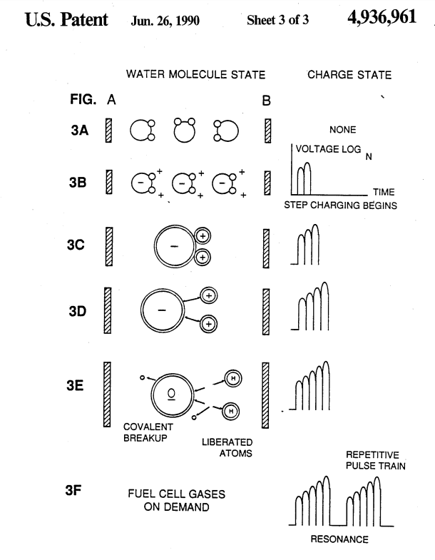
Description of the Preferred Embodiment
In brief, the invention is a method of obtaining the release of a gas mixture including hydrogen and oxygen and other dissolved gases formerly entrapped in water, from water consisting of:
(A) providing a capacitor, in which the water is included as a dielectric liquid between capacitor plates, in a resonant charging choke circuit that includes an inductance in series with the capacitor;
(B) subjecting the capacitor to a pulsating, uni-polar electric voltage field in which the polarity does not pass beyond an arbitrary ground, whereby the water molecules within the capacitor are subjected to a charge of the same polarity and the water molecules are distended by their subjection to electrical polar forces;
(C) further subjecting the water in said capacitor to said pulsating electric field to achieve a pulse frequency such that the Pulsating electric field induces a resonance within the water molecule;
(D) continuing the application of the pulsing frequency to the capacitor cell after resonance occurs so that the energy level within the molecule is increased in cascading incremental steps in proportion to the number of pulses;
(E) maintaining the charge of said capacitor during the application of the pulsing field, whereby the covalent electrical bonding of the hydrogen and oxygen atoms within said molecules is destabilized such that the force of the electrical field applied, as the force is effective within the molecule, exceeds the bonding force of the molecule, and hydrogen and oxygen atoms are liberated from the molecule as elemental gases; and
(F) collecting said hydrogen and oxygen gases, and any other gases that were formerly dissolved within the water, and discharging the collected gases as a fuel gas mixture.
The process follows the sequence of steps shown in the following Table I in which water molecules are subjected to increasing electrical forces. In an ambient state, randomly oriented water molecules are aligned with respect to a molecular polar orientation. They are next, themselves polarized and “elongated” by the application of an electric Potential to the extent that covalent bonding of the water molecule is so weakened that the atoms disassociate and the molecule breaks down into hydrogen and oxygen elemental components. Engineering design parameters based on known theoretical principles of electrical circuits determine the incremental levels of electrical and wave energy input required to produce resonance in the system whereby the fuel gas comprised of a mixture of hydrogen, oxygen, and the other gases such as air test were formerly dissolved within the water, is produced.
TABLE I
PROCESS STEPS THE SEQUENCE OF THE RELATIVE STATE OF THE WATER MOLECULE AND/OR HYDROGEN/OXYGEN/OTHER ATOMS: .
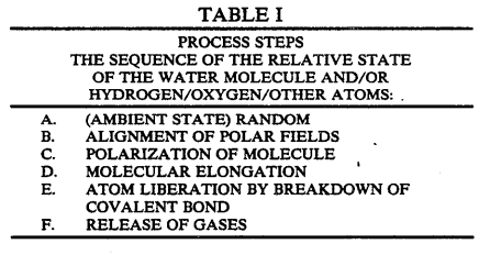
(AMBIENT STATE)
RANDOM ALIGNMENT OF POLAR FIELDS
POLARIZATION OF MOLECULE
MOLECULAR ELONGATION
ATOM LIBERATION BY BREAKDOWN OF COVALENT BOND
RELEASE OF GASES
In the process, the point of optimum gas release is reached at a circuit resonance. Water in the fuel cell is subjected to a pulsating, polar electric field produced by the electrical circuit whereby the water molecules are distended by reason of their subjection to electrical polar forces of the capacitor plates. The polar pulsating frequency applied is such that the pulsating electric field induces a resonance in the molecule. A cascade effect occurs and the overall energy level of specific water molecules is increased in cascading, incremental steps. The hydrogen and oxygen atomic gases, and other gas components formerly entrapped as dissolved gases in water, are released when the resonant energy exceeds the covalent bonding force of the water molecule. A preferred construction material for the capacitor plates is a stainless steel T-304 which is non-chemically reactive with water, hydrogen, or oxygen. An electrically conductive material which is inert in the fluid environment is a desirable material of construction for the electrical field plates of the “water capacitor” employed in the circuit.
Once triggered, the gas output is controllable by the attenuation of operational parameters. Thus, once the frequency of resonance is identified, by varying the applied pulse voltage to the water fuel cell assembly, gas output is varied. By varying the pulse shape and/or amplitude or pulse train sequence of the initial pulsing wave source, final gas output is varied. Attenuation of the voltage field frequency in the form of OFF and ON pulses likewise affects output.
The overall apparatus thus includes an electrical circuit in which a water capacitor having a known dielectric property is an element. The fuel gases are obtained from the water by the disassociation of the water molecule. The water molecules are split into component atomic elements (hydrogen and oxygen gases) by a voltage stimulation process called the electrical polarization process which also releases dissolved gases en- trapped in the water.
From the outline of physical phenomena associated with the process described in Table 1, the theoretical basis of the invention considers the respective states of molecules and gases and ions derived from liquid water. Before voltage stimulation, water molecules are randomly dispersed throughout water within a container. When a uni-polar voltage pulse train such as shown in FIGS. 3B through 3F is applied to positive and negative capacitor plates, an increasing voltage potential is induced in the molecules in a linear, step-like charging effect. The electrical field of the particles within a volume of water including the electrical field plates increases from a low energy state to a high energy state successively in a step manner following each pulse-train as illustrated figuratively in the depictions of FIG. 3A through 3F. The increasing voltage potential is always positive in direct relationship to negative ground potential during each pulse. The voltage polarity on the plates which create the voltage fields remains constant although the voltage charge increases. Positive and negative voltage “zones” are thus formed simultaneously in the electrical field of the capacitor plates.
In the first stage of the process described in Table 1, because the water molecule naturally exhibits opposite electrical fields in a relatively polar configuration (the two hydrogen atoms are positively electrically charged relative to the negative electrically charged oxygen atom), the voltage pulse causes initially randomly oriented water molecules in the liquid state to spin and orient themselves with reference to positive and negative poles of the voltage fields applied. The positive electrically charged hydrogen atoms of said water molecule are attracted to a negative voltage field; while, at the same time, the negative electrically charged oxygen atoms of the same water molecule are attracted to a positive voltage field. Even a slight potential difference applied to inert, conductive plates of a containment chamber which forms a capacitor will initiate polar atomic orientation within the water molecule based on polarity differences.
When the potential difference applied causes the orientated water molecules to align themselves between the conductive plates, pulsing causes the voltage field intensity to be increased in accordance with FIG. 3B. As further molecular alignment occurs, molecular movement is hindered. Because the positively charged hydrogen atoms of said aligned molecules are attracted in a direction opposite to the negatively charged oxygen atoms, a polar charge alignment or distribution occurs within the molecules between said voltage zones, as shown in FIG. 3B. And as the energy level of the atoms subjected to resonant pulsing increases, the stationary water molecules become elongated as shown in FIGS. 3C and 3D. Electrically charged nuclei and electrons are attracted toward opposite electrically charged voltage zones -- disrupting the mass and charge equilibrium of the water molecule.
As the water molecule is further exposed to an increasing potential difference resulting from the step charging of the capacitor, the electrical force of attraction of the atoms within the molecule to the capacitor plates of the chamber also increases in strength. As a result, the covalent bonding between atoms which form the molecule is weakened -- and ultimately terminated. The negatively charged electron is attracted toward the positively charged hydrogen atoms, while at the same time, the negatively charged oxygen atoms repel electrons.
In a more specific explanation of the “sub-atomic” action that occurs in the water fuel cell, it is known that natural water is a liquid which has a dielectric constant of 78.54 at 20° C. and 1 atm pressure.
Source: [Handbook af Chemistry and Physics, 68th ed., CRC Press (Boca Ra- ton, Florida (1987-88)), Section E-50. H2O (water)].
When a volume of water is isolated and electrically conductive plates, that are chemically inert in water and are separated by a distance, are immersed in the water, a capacitor is formed, having a capacitance determined by the surface area of the plates, the distance of their separation and the dielectric constant of water.
When water molecules are exposed to voltage at a restricted current, water takes on an electrical charge. By the laws of electrical attraction, molecules align according to positive and negative polarity fields of the molecule and the alignment field. The plates of a capacitor constitute such an alignment field when a voltage is applied.
When a charge is applied to a capacitor, the electrical charge of the capacitor equals the applied voltage charge; in a water capacitor, the dielectric property of water resists the flow of amps in the circuit, and the water molecule itself, because it has polarity fields formed by the relationship of hydrogen and oxygen in the covalent bond, and an intrinsic dielectric property, becomes part of the electrical circuit, analogous to a “micro-capacitor” within the capacitor defined by the plates.
In the Example of a fuel cell circuit of FIG. 1, a water capacitor is included. The step-up coil is formed on a conventional toroidal core formed of a compressed ferromagnetic powdered material that will not itself become permanently magnetized, such as the trade- marked “Ferramic 06# “Permag” powder as described in Siemens Ferrites Catalog,.CG-2000-002-121, (Cleveland, Ohio) No. F626-1205. The core is 1.50 inch in diameter and 0.25 inch in thickness. A primary coil of 200 turns of 24 gauge copper wire is provided and a coil of 600 turns of 36 gauge wire comprises the secondary winding.
In the circuit of FIG. 1, the diode is a IN1198 diode which acts as a blocking diode and an electric switch that allows voltage flow in one direction only. Thus, the capacitor is never subjected to a pulse of reverse polarity.
The primary coil of the toroid is subject to a 50% duty cycle pulse. The toroidal pulsing coil provides a voltage step-up from the pulse generator in excess of five times, although the relative amount of step-up is determined by pre-selected criteria for a particular application. As the stepped-up pulse enters first inductor (formed from 100 turns of 24 gauge wire 1" inch in diameter), an electromagnetic field is formed around the inductor, voltage is switched off when the pulse ends, and the field collapses and produces another pulse of the same polarity; i.c., another positive pulse is formed where the 50% duty cycle was terminated. Thus, a double pulse frequency is produced; however, in a pulse train of uni-polar pulses, there is a brief time when pulses are not present.
By being so subjected to electrical pulses in the circuit of FIG. 1, water confined in the volume that includes the capacitor plates takes on an electrical charge that is increased by a step charging phenomenon occurring in the water capacitor. Voltage continually increases (to about 1000 volts and more) and the water molecule starts to elongate.
The pulse train is then switched off; the voltage across the water capacitor drops to the amount of charge that the water molecules have taken on, i.e. voltage is maintained across the charged capacitor. The pulse train is then reapplied.
Because a voltage potential applied to a capacitor can perform work, the higher the voltage potential, the more work is performed by a given capacitor. In an optimum capacitor that is wholly non-conductive, zero (0) current flow will occur across the capacitor. Thus, in view of an idealized capacitor circuit, the object of the water capacitor circuit is to prevent electron flow through the circuit, i.e. such as occurs by electron flow or leakage through a resistive element that produces heat. Electrical leakage in water will occur, however, because of some residual conductivity and impurities or ions that may be otherwise present in the water. Thus, the water capacitor is preferably chemically inert. An electrolyte is not added‘to the water.
In the isolated water bath, the water molecule takes on charge, and the charge increases. The object of the process is to switch off the covalent bonding of the water molecule and interrupt the sub-atomic force, i.e. the electrical force or electromagnetic force, that binds the hydrogen and oxygen atoms to form a molecule so that the hydrogen and oxygen separate.
Because an electron will only occupy a certain electron shell (the shells are well known) the voltage applied to the capacitor affects the electrical forces inherent in the covalent bond. As a result of the charge applied by the plates, the applied force becomes greater than the force of the covalent bonds between the atom of the water molecule; and the water molecule becomes elongated. When this happens, the time share ratio of the electrons between the atoms and the electron shells is modified.
In the process, electrons are extracted from the water bath; electrons are not consumed, nor are electrons introduced into the water bath by the circuit as electrons are conventionally introduced in an electrolysis process. There may nevertheless occur a leakage current through the water. Those hydrogen atoms missing electrons become neutralized; and atoms are liberated from the water. The charged atoms and electrons are attracted to opposite polarity voltage zones created between the capacitor plates. The electrons formerly shared by atoms in the water covalent bond are re- allocated such that neutral elemental gases are liberated.
In the process, the electrical resonance may be reached at all levels of voltage potential. The overall circuit is characterized as a “resonant charging choke” circuit which is an inductor in series with a capacitor that produces a resonant circuit.
Source: [SAMS Modern Dictio- nary of Electronics, Rudolff Garff, © 1984, Howard W. Sams & Co. (Indianapolis, Ind.), page 859.]
Such a resonant charging choke is on each side of the capacitor. In the circuit, the diode acts as a switch that allows the magnetic field produced in the inductor to collapse, thereby doubling the pulse frequency and preventing the capacitor from discharging. In this manner a continuous voltage is produced across the capacitor plates in the water bath; and the capacitor does not discharge. The water molecules are thus subjected to a continuously charged field until the breakdown of the covalent bond occurs.
As noted initially, the capacitance depends on the dielectric properties of the water and the size and separation of the conductive elements forming the water capacitor.
EXAMPLE I
In an example of the circuit of FIG. 1. (in which other circuit element specifications are provided above), two concentric cylinders 4 inches long formed the water capacitor of the fuel cell in the volume of water. The outside cylinder was 0.75 inch in outside diameter; the inner cylinder was 0.5 inch in outside diameter. Spacing from the outside of the inner cylinder to the inner surface of the outside cylinder was 0.0625 inch.
Resonance in the circuit was achieved at a 26 volt applied pulse to the primary coil of the toroid at 10 kHz, and the water molecules disassociated into elemental hydrogen and oxygen and the gas released from the fuel cell comprised a mixture of hydrogen, oxygen from the water molecule, and gases formerly dissolved in the water such as the atmospheric gases or oxygen, nitrogen, and argon.
In achieving resonance in any circuit, as the pulse frequency is adjusted, the flow of amps is minimized and voltage is maximized to a peak. Calculation of the resonance frequency of an overall circuit is determined by known means; different cavities have a different frequency of resonance dependent on parameters of the water dielectric, plate size, configuration and distance, circuit inductors, and the like. Control of the production of fuel gas is determined by variation of the period of time between a train of pulses, pulse amplitude and capacitor plate size and configuration, with corresponding value adjustments to other circuit components.
The wiper arm on the second inductor tunes the circuit and accommodates to contaminants in water so that the charge is always applied to the capacitor. The voltage applied determines the rate of breakdown of the molecule into its atomic components. As water in the cell is consumed, it is replaced by any appropriate means or control system.
Variations of the process and apparatus may be evident to those skilled in the art.
What is claimed is:
1. A method of obtaining the release of a gas mixture including hydrogen and oxygen and other dissolved gases formerly entrapped in water, from water, consisting of:
(A) providing a capacitor in which water is included as a dielectric between capacitor plates, in a resonant charging choke circuit that includes an inductance in series with the capacitor;
(B) subjecting the capacitor to a pulsating, uni-polar electric charging voltage in which the polarity does not pass beyond an arbitrary ground, whereby the water molecules within the capacitor are subjected to the. electric field between the capacitor plates;
(C) further subjecting the water in said capacitor to a pulsating electric field resulting from the subjection of the capacitor to the charging voltage such that the pulsating electric field induces a resonance within the water molecules; 4,936,961
(D) continuing the application of the pulsating charg- ing voltage to the capacitor after resonance occurs so that the energy level within the molecules is increased in cascading incremental steps in proportion to the number of pulses;
(E) maintaining the charge of said capacitor during the application of the pulsating charging voltage, whereby the covalent electrical bonding of the hydrogen and oxygen atoms within said molecules is destabilized, such that the force of the electrical field applied to the molecules exceeds the bonding force within the molecules, and hydrogen and oxygen atoms are liberated from the molecules as elemental gases.
2. The method of claim 1 including the further steps of collecting said liberated hydrogen and oxygen gases, and any other gases that were formerly dissolved with in the water and discharging said collected gases as a fuel gas mixture.
Process & Apparatus For The Production Of Fuel Gas & The Enhanced Release Of Thermal Energy From Such Gas #5,149,407
PDF Download: Meyer #5,149,407 Process & Apparatus For The Production Of Fuel Gas & The Enhanced Release Of Thermal Energy From Such Gas.pdf
ABSTRACT:
Water molecules are broken down into hydrogen and oxygen gas atoms in a capacitive cell by a polarization and resonance process dependent upon the dielectric properties of water and water molecules. The gas atoms are thereafter ionized or otherwise energized and thermally combusted to release a degree of energy greater than that of combustion of the gas in ambient air.
FIELD OF THE INVENTION:
This invention relates to a method of and apparatus for obtaining the release of a fuel gas mixture including hydrogen and oxygen from water and to a method of and apparatus for obtaining the further release of energy from such a fuel gas mixture. Charged ions derived from the fuel gas are stimulated to an activated state, and then passed through a resonant cavity, where successively increasing energy levels are achieved, and finally passed to an outlet orifice to produce thermal explosive energy.
PRIOR ART:
Numerous processes have been proposed for separating a water molecule into its elemental hydrogen and oxygen components. Electrolysis is one such process. Other processes are described in U.S. patents such as U.S. Pat. Nos. 4,344,831; 4,184,931; 4,023,545; 3,980,053; and Patent Cooperation Treaty Application No. PCT/US80/1362, published Apr. 30, 1981. Other processes have been proposed for many years in which controlled energy producing reactions of atomic particles are expected to occur under “cold” conditions. [See, e.g., Rafelski, J. and Jones, 8. E., “Cold Nuclear Fusion,” Scientific American, July, 1987, page 84].
Further processes are also described in U.S. Pat. Nos. 4,233,109; 4,406,765; 4,687,753 and 4,695,357. The process and apparatus described herein are considered variations to and improvements in fuel sources and processes by which energy is derived from fuel gas components in a controllable manner.
OBJECTS OF THE INVENTION:
- A first object of the invention is to provide a fuel cell and a process in which molecules of water are broken down into hydrogen and oxygen gases, and a fuel gas mixture including hydrogen, oxygen and other gasses formerly dissolved within the water is produced. A further object of the invention is to realize significant energy-yield from a fuel gas derived from water (H20) molecules. Molecules of water are broken down into hydrogen and oxygen gases. Electrically charged hydrogen and oxygen ions of opposite electrical polarity are activated by electromagnetic wave energy and ex- posed to a high temperature thermal zone. Significant amounts of thermal energy with explosive force beyond the gas burning stage are released.
- An explosive thermal energy under a controlled state is produced. The process and apparatus provide a heat energy source useful for power generation, aircraft, rocket engines, or space stations.
DRAWINGS:
FIG. 1: 1A through 1F are illustrations depicting the theoretical bases for phenomena encountered during operation of the fuel gas production stage of the invention herein.
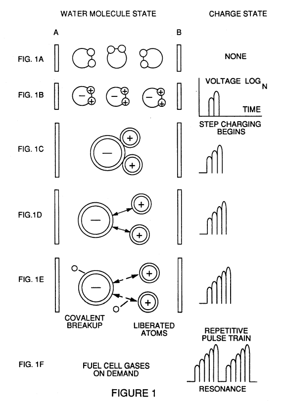
TABLE 1:
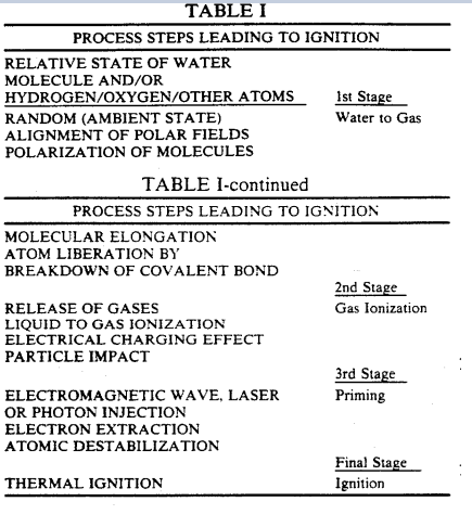
FIG. 2 Illustrates a circuit useful in the fuel gas generation process.
FIG. 3 shows a perspective of a “water capacitor” element used in the fuel cell circuit.
FIG. 4 illustrates a staged arrangement of apparatus useful in the process, beginning with a water inlet and culminating in the production of thermal explosive energy.
FIG. 5A shows a cross-section of a circular gas resonant cavity used in the final stage assembly of FIG. 4
FIG. 5B shows an alternative final stage injection system useful in the apparatus of FIG. 4.

FIG. 5C shows an optical thermal lens assembly for use with either final stage of FIG. 5A or FIG. 5B
FIGS. 6A, 6B, 6C and 6D are illustrations depicting various theoretical bases for atomic phenomena expected to occur during operation of the invention herein.
FIG. 7 is an electrical schematic of the voltage source for the gas resonant cavity.
FIGS. 8A and 8B, respectively, show (A) an electron extractor grid used in the injector assemblies of FIG. 5A and FIG. 5B, and (B) the electronic control circuit for the extractor grid.
FIG. 9 shows an alternate electrical circuit useful in providing a pulsating waveform to the apparatus.
DESCRIPTION OF THE PREFERRED EMBODIMENT:
A fuel gas is produced by a hydrogen fracturing process that follows the sequence of steps shown in the following Table I. Beginning with water molecules, the molecule is subjected to successively increasing electrical, wave energy and thermal forces. In the succession of forces, randomly oriented water molecules are aligned with respect to molecular polar orientation and them- selves polarized and “elongated” by the application of an electric potential to the extent that covalent bonding of the water molecule is so weakened that the atoms disassociate and the molecule breaks down into hydro- gen and oxygen elemental components. The released atomic gases are next ionized and electrically charged in a vessel while being subjected to a further energy source that promotes inter-particle impact in the gas at an increased overall energy level. Finally, the atomic particles in the excited gas, having achieved successively higher energy levels, are subjected to a laser or electromagnetic wave energy source that produces atomic destabilization and the final release of thermal explosive energy. Engineering design parameters based on known theoretical principles of atomic physics determine the incremental levels of electrical and wave energy input required to produce resonance in each stage of the system. Instead of a dampening effect, a resonant energization of the molecule, atom or ion provides a compounding energy interaction resulting in the final energy release.
In brief, in the first stage a gas mixture including hydrogen and oxygen and other dissolved gases formerly entrapped in water is obtained, from water.
In general, the method used in the first stage consists of:
-
(A) providing a capacitor, in which the water is included as a dielectric liquid between capacitor plates, in a resonant charging choke circuit that includes an inductance in series with the capacitor.
-
(B) subjecting the capacitor to a pulsating, unipolar electric voltage field in which the polarity does not pass beyond an arbitrary ground, whereby the water molecules within the capacitor are subjected to a charge of the same polarity and the water molecules are distended by their subjection to electrical polar forces.
-
(C) further subjecting the water in said capacitor to said pulsating electric field to achieve a pulse frequency such that the pulsating electric field induces a resonance within the water molecule.
-
(D) continuing the application of the pulsing frequency to the capacitor cell after resonance occurs so that the energy level within the molecule is increased in cascading incremental steps in proportion to the number of pulses.
-
(E) maintaining the charge of said capacitor during the application of the pulsing field, whereby the co-valent electrical bonding of the hydrogen and oxygen atoms within said molecules is destabilized such that the force of the electrical field applied, as the force is effective within the molecule, exceeds the bonding force of the molecule, and hydrogen and oxygen atoms are liberated from the molecule as elemental gases; and
-
(F) collecting said hydrogen and oxygen gases, and any other gases that were formerly dissolved within. the water, and discharging the collected gases as a fuel gas mixture.
The water molecules are subjected to increasing electrical forces. In an ambient state, randomly oriented water molecules are aligned with respect to a molecular polar orientation. They are next, themselves polarized and “elongated” by the application of an electric potential to the extent that covalent bonding of the water molecule is so weakened that the atoms disassociate and the molecule breaks down into hydrogen and oxygen elemental components. In the process, the point of optimum gas release is reached at a circuit resonance. Water in the fuel cell is subjected to a pulsating, polar electric field produced by the electrical circuit whereby the water molecules are distended by reason of their subjection to electrical polar forces of the capacitor plates. The polar pulsating frequency applied is such that the pulsating electric field induces a resonance in the molecule. A cascade effect occurs and the overall energy level of specific water molecules is increased in cascading, incremental steps. The hydrogen and oxygen atomic gases, and other gas components formerly entrapped as dissolved gases in water, are released when the resonant energy exceeds the covalent bonding force of the water molecule. A preferred construction material for the capacitor plates is a stainless steel T-304 which is non-chemically reactive with water, hydro- gen, or oxygen. An electrically conductive material which is inert in the fluid environment is a desirable material of construction for the electric field plates of the “water capacitor” employed in the circuit.
Once triggered, the gas output is controllable by the attenuation of operational parameters. Thus, once the frequency of resonance is identified, by varying the applied pulse voltage to the water fuel cell assembly, gas output is varied. By varying the pulse shape and/or amplitude or pulse train sequence of the initial pulsing wave source, final gas output is varied. Attenuation of the voltage field frequency in the form of OFF and ON pulses likewise affects output.
The overall apparatus thus includes an electrical circuit in which a water capacitor having a known dielectric property is an element. The fuel gases are obtained from the water by the disassociation of the water molecule. The water molecules are split into component atomic elements (hydrogen and oxygen gases) by a voltage stimulation process called the electrical polarization process which also releases dissolved gases entrapped in the water.
From the outline of physical phenomena associated with the first stage of the process described in Table 1, the theoretical basis of the invention considers the respective states of molecules and gases and ions derived from liquid water. Before voltage stimulation, water molecules are randomly dispersed throughout. water within a container. When a unipolar voltage pulse train such as shown in FIGS. 1B through JF is applied to positive and negative capacitor plates, an increasing voltage potential is induced in the molecules in a linear, step-like charging effect. The electrical field of the particles within a volume of water including the electrical field plates increases from a low energy state to a high energy state successively in a step manner following each pulse-train as illustrated figuratively in the depictions of FIGS. 1A through 1F. The increasing voltage potential is always positive in direct relation- ship to negative ground potential during each pulse. The voltage polarity on the plates. which create the voltage fields remains constant although the voltage charge increases. Positive and negative voltage “zones” are thus formed simultaneously in the electrical field of the capacitor plates.
In the first stage of the process describe in Table 1, because the water molecule naturally exhibits opposite electrical fields in a relatively polar configuration (the two hydrogen atoms are positively electrically charged relative to the negative electrically charged oxygen atom), the voltage pulse causes initially randomly oriented water molecules in the liquid state to spin and orient themselves with reference to positive and negative poles of the voltage fields applied. The positive electrically charged hydrogen atoms of said water molecule are attracted to a negative voltage field; while, at the same time, the negative electrically charged oxygen atoms of the same water molecule are attracted to a positive voltage field. Even a slight potential difference applied to inert, conductive plates of a containment chamber which forms a capacitor will initiate polar 5,149,407 atomic orientation within the water molecule based on polarity differences.
When the potential difference applied causes the orientated water molecules to align themselves between the conductive plates, pulsing causes the voltage field intensity to be increased in accordance with FIG. 1B. As further molecular alignment occurs, molecular movement is hindered. Because the positively charged hydrogen atoms of said aligned molecules are attracted in a direction opposite to the negatively charged oxygen atoms, a polar charge alignment or distribution occurs within the molecules between said voltage zones, as shown in FIG. 1B. And as the energy level of the atoms subjected to resonant pulsing increases, the stationary water molecules become elongated as shown in FIGS. 1C and 1D. Electrically charged nuclei and electrons are attracted toward opposite electrically charged voltage zones—disrupting the mass and charge equilibrium of the water molecule.
As the water molecule is further exposed to an in- creasing potential difference resulting from the step charging of the capacitor, the electrical force of attraction of the atoms within the molecule to the capacitor plates of the chamber also increases in strength. As a result, the covalent bonding between atoms which form the molecule is weakened—and ultimately terminated. The negatively charged electron is attracted toward the positively charged hydrogen atoms, while at the same time, the negatively charged oxygen atoms repel electrons.
In a more specific explanation of the “sub-atomic” action that occurs in the water cell that provides a fuel gas for the subsequent stages, it is known that natural water is a liquid which has a dielectric constant of 78.54 at 20° C. and 1 atm pressure. [Handbook of Chemistry and Physics, 68th ed., CRC Press (Boca Raton, Fla. (1987~-88)), Section E-50, HzO (water)].
When a volume of water is isolated and electrically conductive plates, that are chemically inert in water and are separated by a distance, are immersed in the water, a capacitor is formed, having a capacitance determined by the surface area of the plates, the distance of their separation and the dielectric constant of water.
When water molecules are exposed to voltage at a restricted current, water takes on an electrical charge. By the laws of electrical attraction, molecules align according to positive and negative polarity fields of the molecule and the alignment field. The plates of a capacitor constitute such an alignment field when a voltage is applied.
When a charge is applied to a capacitor, the electrical charge of the capacitor equals the applied voltage charge; in a water capacitor, the dielectric property of water resists the flow of amps in the circuit, and the water molecule itself, because it has polarity fields formed by the relationship of hydrogen and oxygen in the covalent bond, and an intrinsic dielectric property, becomes part of the electrical circuit, analogous to a “micro-capacitor” within the capacitor defined by the plates.
In the Example of a fuel cell circuit of FIG. 2, a water capacitor is included. The step-up coil is formed on a conventional torroidal core formed of a compressed ferromagnetic powdered material that will not itself become permanently magnetized, such as the trademarked Ferramic 06# “Permag” powder as described in Siemens Ferrites Catalog, CG-2000-002-121, (Cleve- land, Ohio) No. F626-1205.
The core is 1.50 inch in 6 diameter and 0.25 inch in thickness. A primary coil of 200 turns of 24 gauge cooper wire is provided and a coil of 600 turns of 36 gauge wire comprises the secondary winding. Other primary/secondary coil winding ratios may be conventionally determined.
An alternate coil arrangement using a conventional M27 iron transformer core is shown in FIG. 9. The coil wrap is always in one direction only.
In the circuit of FIG. 2, the diode is a IN1198 diode which acts as a blocking diode and an electric switch that allows voltage flow in one direction only. Thus, the capacitor is never subjected to a pulse of reverse polarity.
The primary coil of the toroid is subject to a 50% duty cycle pulse. The toroidal pulsing coil provides a voltage step-up from the pulse generator in excess of five times, although the relative amount of step-up is determined by pre-selected criteria for a particular application. As the stepped-up pulse enters first inductor (formed from 100 turns of 24 gauge wire | inch in diameter), an electromagnetic field is formed around the inductor, voltage is switched off when the pulse ends, and the field collapses and produces another pulse of the same polarity; i.e., another positive pulse is formed where the 50% duty cycle was terminated. Thus, a double pulse frequency is produced; however, in a pulse train of unipolar pulses, there is a brief time when pulses are not present.
By being so subjected to electrical pulses in the circuit of FIG. 2, water confined in the volume that includes the capacitor plates takes on an electrical charge that is increased by a step charging phenomenon occurring in the water capacitor. Voltage continually increases (to about 1000 volts and more) and the water molecules starts to elongate.
The pulse train is then switched off, the voltage across the water capacitor drops to the amount of charge that the water molecules have taken on, i.e. voltage is maintained across the charged capacitor. The pulse train is then reapplied.
Because a voltage potential applied to a capacitor can perform work, the higher the voltage potential, the more work is performed by a given capacitor. In an optimum capacitor that is wholly non-conductive, zero (0) current flow will occur across the capacitor. Thus, in view of an idealized capacitor circuit, the object of the water capacitor circuit is to prevent electron flow through the circuit, ie. such as occurs by electron flow or leakage through a resistive element that produces heat. Electrical leakage in water will occur, however, because of some residual conductivity and impurities or ions that may be otherwise present in the water. Thus, the water capacitor is preferably chemically inert. An electrolyte is not added to the water.
In the isolated water bath, the water molecule takes on charge, and the charge increases. The object of the process is to switch off the covalent bonding of the water molecule and interrupt the sub-atomic force, i.e. the electrical force or electromagnetic force, that binds the hydrogen and oxygen atoms to form a molecule so that the hydrogen and oxygen separate.
Because an electron will only occupy a certain electron shell (the shells are well known) the voltage applied to the capacitor affects the electrical forces inherent in the covalent bond. As a result of the charge applied by the plates, the applied force becomes greater than the force of the covalent bonds between the atoms of the water molecule; and the water molecule becomes elongated. When this happens, the time share ratio of the electrons between the atoms and the electron shells is modified.
In the process, electrons are extracted from the water bath; electrons are not consumed nor are electrons introduced into the water bath by the circuit as electrons are conventionally introduced in an electrolysis process. There may nevertheless occur a leakage current through the water. Those hydrogen atoms missing electrons become neutralized; and atoms are liberated from the water. The charged atoms and electrons are attracted to opposite polarity voltage zones created be- tween the capacitor plates. The electrons formerly shared by atoms in the water covalent bond are re- allocated such that neutral elemental gases are liberated.
In the process, the electrical resonance may be reached at all levels of voltage potential. The overall circuit is characterized as a “resonant charging choke” circuit which is an inductor in series with a capacitor that produces a resonant circuit. [S4MS Modern Dictionary of Electronics, Rudolff Garff, ©1984, Howard W. Sams & Co. (Indianapolis, Ind.), p. 859.] Such a resonant charging choke is on each side of the capacitor. In the circuit, the diode acts as a switch that allows the magnetic field produced in the inductor to collapse, thereby doubling the pulse frequency and preventing the capacitor from discharging. In this manner a continuous voltage is produced across the capacitor plates in the water bath; and the capacitor does not discharge. The water molecules are thus subjected to a continuously charged field until the breakdown of the covalent bond occurs.
As noted initially, the capacitance depends on the dielectric properties of the water and the size and separation of the conductive elements forming the water capacitor.
EXAMPLE I
In an example of the circuit of FIG. 2 (in which other circuit element specifications are provided above), two concentric cylinders 4 inches long formed the water capacitor of the fuel cell in the volume of water. The outside cylinder was 0.75 inch in outside diameter; the inner cylinder was 0.5 inch in outside diameter. Spacing from the outside of the inner cylinder to the inner surface of the outside cylinder was 0.0625 inch. Resonance in the circuit was achieved at a 26 volt applied pulse to the primary coil of the toroid at 10 KH,, and the water molecules disassociated into elemental hydrogen and oxygen and the gas released from the fuel cell comprised a mixture of hydrogen, oxygen from the water molecule, and gases formerly dissolved in the water such as the atmospheric gases or oxygen, nitro- gen, and argon.
In achieving resonance in any circuit, as the pulse frequency is adjusted, the flow of amps is minimized and voltage is maximized to a peak. Calculation of the resonance frequency of an overall circuit is determined by known means; different cavities have a different frequency of resonance dependent on parameters of the water dielectric, plate size, configuration and distance, circuit inductors, and the like. Control of the production of fuel gas is determined by variation of the period of time between a train of pulses, pulse amplitude and capacitor plate size and configuration, with corresponding value adjustments to other circuit components. The wiper arm on the second inductor tunes the circuit and accommodates to contaminants in water so that the charge is always applied to the capacitor. The voltage applied determines the rate of breakdown of the molecule into its atomic components. As water in the cell is consumed, it is replaced by any appropriate means or control system.
Thus in the first stage, which is of itself independently useful, a fuel gas mixture is produced having, in general, the components of elemental hydrogen and oxygen as well as formerly dissolved entrapped atmospheric gases such as nitrogen, argon, and the like. The fuel gas is itself combustible in a conventional manner.
After the first stage the gas atoms become elongated during electron removal as the atoms are ionized. Laser, or light wave energy of a predetermined frequency is injected into a containment vessel in a gas ionization process. The light energy absorbed by voltage stimulated gas nuclei causes destabilization of gas ions still further. The absorbed laser energy causes the gas nuclei to increase in energy state, which, in turn, causes electron deflection to a higher orbital shell.
The electrically charged and laser primed combustible gas ions from a gas resonant cavity may be directed into an optical thermal lens assembly for triggering. Before entry into the optimal thermal lens, however, electrons are stripped from the ions and the atom is destabilized. The destabilized gas ions which are electrically and mass unbalanced atoms having highly energized nuclei are pressurized during spark ignition. The unbalanced, destabilized atomic components thermally interact; the energized and unstable hydrogen gas nuclei collide with highly energized and unstable oxygen gas nuclei, causing and producing thermal explosive energy beyond the gas burning stage. The ambient air gas components in the initial mixture aid the thermal explosive process under a controlled state.
In the process, the point of optimum energy-yield is reached when the electron deficient oxygen atoms (having less than a normal number of electrons) lock onto and capture a hydrogen atom electron prior to or during thermal combustion of the hydrogen/oxygen mixture. Atomic decay results in the release of energy.
After the first stage, the gas mixture is subjected to a pulsating, polar electric field whereby electrons of the gas atoms are distended in their orbital fields by reason of their subjection to electrical polar forces The polar pulsating frequency applied is such that the pulsating electric field induces a resonance with respect to an electron of the gas atom. A cascade effect results and the energy level of specific resonating electron is in- creased in cascading, incremental steps.
Next, the gas atoms are ionized and subjected to electro-magnetic wave energy having a predetermined frequency to induce a further election resonance in the ion, whereby the energy level of the election is successively increased. Electrons are extracted from the resonating ions while such ions are in an increased energy state to destabilize the nuclear electron configuration of said ions; and the gas mixture of destabilized ions is thermally ignited.
In the apparatus shown in FIG. 4, water is introduced at inlet 1 into a first stage water fracturing module 2, such as the water fuel cell described above, in which water molecules are broken down into hydrogen, oxy- gen and released entrapped gas components. The re- leased atomic gases and other gas components formerly entrapped as dissolved gases in water may be introduced to a successive stage 3 or other number of like resonant cavities, which are arranged in either a series of parallel combined array. The successive energization of the gas atoms provides a cascading effect, successively increasing the voltage stimulation level of the released gasses as they sequentially pass through cavities 2, 3, etc. In a final stage, an injector system 4, of a configuration of the type shown in FIGS. 5A or 5B, receives energized atomic and gas particles where the particles are subjected to further energy input, electrical excitation and thermal stimulation, whereby thermal explosive energy results 5, which may be directed thru a lens assembly of the type shown in FIG. 5C to provide a controlled thermal energy output.
A single cell, or a battery of cells such as shown in FIG. 3, provides a fuel gas source for stages after the first stage. The fuel gas is activated by electromagnetic waves, and electrically charged gas ions of hydrogen and oxygen (of opposite polarity) are expelled from the cascaded cells 2, 3, etc. shown in FIG. 4. The circuit of FIG. 9 may be utilized as a source of ionizing energy for the gases. The effect of cascading successively increases the voltage stimulation level of the released gases, which then are directed to the final injector assembly 4. In the injector assembly, gas ions are stimulated to a yet higher energy level. The gases are continually exposed to a pulsating laser or other electromagnetic wave energy source together with a high intensity oscillating voltage field that occurs within the cell between electrodes or conductive plates of opposite electrical polarity. A preferred construction material for the plates is a stainless steel T-304 which is non-chemically reactive with water, hydrogen, or oxygen. An electrically conductive material which is insert in the fluid environment is a desirable material of construction for the electrical field producing plates, through which field the gas stream of activated particles passes. Gas ions of opposite electrical charges reach and maintain a critical energy level state. The gas ions are oppositely electrically charged and subjected to oscillating voltage fields of opposite polarity and are also subjected to a pulsating electromagnetic wave energy source. Immediately after reaching critical energy, the excited gas ions are ex- posed to a high temperature thermal zone in the injection cell, 4, that causes the excited gas ions to undergo gas combustion. The gas ignition triggers atomic decay and releases thermal energy, §, with explosive force.
Once triggered, the thermal explosive energy output is controllable by the attenuation of operational parameters. With reference to FIG. 6A, for example, once the frequency of resonance is identified, by varying applied pulse voltage to the initial water fuel cell assemblies, 2, 3, the ultimate explosive energy output is likewise varied. By varying the pulse shape and/or amplitude or pulse train sequence of the electromagnetic wave energy source, final output is varied. Attenuation of the voltage field frequency in the form of OFF and ON pulses likewise affects output of the staged apparatus. Each control mechanism can be used separately, grouped in sections, or systematically arranged in a sequential manner.
A complete system in accordance with the present application thus includes a water fuel cell for providing a first fuel gas mixture consisting of at least a portion of hydrogen and oxygen gas. An electrical circuit of the type shown in FIG. 7 provides a pulsating, polar electric field to the gas mixture as illustrated in FIG. 6A, whereby electrons of the gas atoms are distended in their orbital fields by reason of their subjection to electrical polar forces, changing from the state conceptually illustrated by FIG. 6B to that of FIG. 6C, at a frequency such that the pulsating electric field induces a resonance with respect to electrons of the gas atoms. The energy level of the resonant electrons is thereby increased in cascading, incremental steps. A further electric field to ionize said gas atoms is applied and an electromagnetic wave energy source for subjecting the ionized gas atoms to wave energy of a predetermined frequency to induce a further electron resonance in the ion, whereby the energy level of the election is successively increased is an additional element of the apparatus as shown in FIG. 6D.
An electron sink, which may be in the form of the grid element shown in FIG. 8A, extracts further electrons from the resonating ions while such ions are in an increased energy state and destabilizes the nuclear electron configuration of the ions. The “extraction” of electrons by the sink means is coordinated with the pulsating electrical field of the resonant cavity produced by the circuit of FIG. 7, by means of an interconnected synchronization circuit, such as shown in FIG. 8B. A nozzle, 10 in FIG. 5B, or thermal lens assembly, FIG. 5C, provides the directing means in which the destabilized ions are finally thermally ignited.
As previously noted, to reach and trigger the ultimate atomic decay of the fuel cell gases at the final stage, sequential steps are taken. First, water molecules are slit into component atomic elements (hydrogen and oxygen gases) by a voltage stimulation process which also re- leases dissolve gases entrapped in the water. In the injector assembly, a laser produced light wave or other form of coherent electromagnetic wave energy capable of stimulating a resonance within the atomic components is absorbed by the mixture of gases (hydrogen/oxygen/ambient air gases) released by the polarization process. At this point, as shown in F1G. 6B, the individual atoms are subjected to an electric field to begin an ionization process.
The laser or electromagnetic wave energy is absorbed and causes gas atoms to lose electrons and form positively charged gas ions. The energized hydrogen atoms which, as ionized, are positively charged, now accept electrons liberated from the heavier gases and attract other negatively charged gas ions as conceptually illustrated in FIG. 6C. Positively and negatively charged gas ions are re-exposed to further pulsating energy sources to maintain random distribution of ionized atomic gas particles.
The gas ions within the wave energy chamber are subjected to an oscillating high intensity voltage field in a chamber 11 in FIGS. 5A and 5B formed within electrodes 12 and 13 in FIGS. 5A and SB of opposite electrical polarity to produce a resonant cavity. The gas ions reach a critical energy state at a resonant state.
At this point, within the chamber, additional electrons are attracted to said positive electrode; whereas, positively charged ions or atomic nuclei are attracted to the negative electrode. The positive and negative at- traction forces are co-ordinate and operate on said gas ions simultaneously; the attraction forces are non-reversible. The gas ions experience atomic component deflection approaching the point of electron separation. At this point electrons are extracted from the chamber by a grid system such as shown in FIG. 5A. The extracted electrons are consumed and prevented from re-entering the chamber by a circuit such as shown in FIG. 8B. The elongated gas ions are subjected to a thermal heat zone to cause gas ignition, releasing thermal energy with explosive force. During ionic gas combustion, highly energized and stimulated atoms and atom nuclei collide and explode during thermal excitation. The hydrogen fracturing process occurring sustains and maintains a thermal zone, at a temperature in excess of normal hydrogen/oxygen combustion temperature, to wit, in excess of 2500° F. To cause and maintain atomic elongation depicted in FIG. 6C before gas ignition, a voltage intensifier circuit such as shown in FIG. 7 is utilized as a current restricting voltage source to provide the excitation voltage applied to the resonant cavity. At the same time the interconnected electron extractor circuit, FIG. 8B, prevents the reintroduction of electrons back into the system. Depending on calculated design parameters, a predetermined voltage and frequency range may be designed for any particular application or physical configuration of the apparatus.
In the operation of the assembly, the pulse train source for the gas resonant cavity shown at 2 and 3 in FIG. 4 may be derived from a circuit such as shown in FIGS. 2, 7 or 9, and such cavity circuits may be in sequence to provide a cascading energy input. It is necessary in the final electron extraction that the frequency with which electrons are removed from the system by sequenced and synchronized with the pulsing of the gas resonant cavity. In the circuit of FIG. 8B, the coordination of synchronization of the circuit with the circuit of FIG. 7 may be achieved by interconnecting point “A” of the gate circuit of FIG. 8B to coordinate point “A” of the pulsing circuit of FIG. 7.
The circuit shown in FIG. 9 enhances the voltage potential across the resonant charging choke coils during pulsing operations and restricts amp flow by allowing an external electromagnetic pulsing field, F, derived from the primary coil A being energized to transverse the coil windings D and E being energized by the incoming pulse train Ha xxx Hn, through switching diode G. The external pulse field, F and the incoming pulse- train Ha xxx Hn, are sequentially the same, allowing resonant action to occur, restricting amp flow while allowing voltage intensity to increase to stimulate the electrical polarization process, the gas ionization process and the electron extraction process. The voltage intensifier circuit of FIG. 9 prevents electrons from entering into those. processes.
Together, the hydrogen injector assembly 4 and the resonant cavity assemblies 2, 3 form a gas injector fuel cell which is compact, light in weight and design vari- able. For example, the hydrogen injector system is suited for automobiles and jet engines. Industrial applications require larger systems. For rocket engine applications, the hydrogen gas injector system is positioned at the top of each resonant cavity arranged in a parallel cluster array. If resonant cavities are sequentially combined in a parallel/series. array, the hydrogen injection assembly is positioned after the exits of said resonant cavities are combined.
From the outline of physical phenomena associated with the process described in Table 1, the theoretical
molecules, gases and ions derived from liquid water. Before voltage stimulation, water molecules are randomly dispersed throughout water within a container. When a unipolar voltage pulse train such as shown in FIG. 6A (53a xxx 53n) is applied, an increasing voltage potential is induced in the molecules, gases and/or ions in-a linear, step-like charging effect. The electrical field of the particles within a chamber including the electrical field plates increases from a low energy state (A) to a high energy state (J) in a step manner following each pulse-train as illustrated in FIG. 6A. The increasing voltage potential is always positive in direct relation- ship to negative ground potential during each pulse. The voltage polarity on the plates which create the voltage fields remains constant. Positive and negative voltage “zones” are thus formed simultaneously.
In the first stage of the process described in Table 1, because the water molecule naturally exhibits opposite electrical fields in a relatively polar configuration (the two hydrogen atoms are positively electrically charged relative to the negative electrically charged oxygen atom), the voltage pulse causes initially randomly oriented water molecules in the liquid state to spin and orient themselves with reference to positive and negative poles of the voltage fields applied. The positive electrically charged hydrogen atoms of said water molecule are attracted to a negative voltage field; while, at the same time, the negative electrically charged oxygen atoms of the same water molecule are attracted to a positive voltage field. Even a slight potential difference applied to the inert, conductive plates of a containment chamber will initiate polar atomic orientation within the water molecule based on polarity differences.
When the potential difference applied causes the orientated water molecules to align themselves between the conductive plates, pulsing causes the voltage field intensity to be increased in accordance with FIG. 6A. As further molecular alignment occurs, molecular movement is hindered. Because the positively charged hydrogen atoms of said aligned molecules are attracted in a direction opposite to the negatively charged oxy- gen atoms, a polar charge alignment or distribution occurs within the molecules between said voltage zones, as shown in FIG. 6B. And as the energy level of the atoms subjected to resonant pulsing increases, the stationary water molecules become elongated as shown in FIG. 6C. Electrically charged nuclei and electrons are attracted toward opposite electrically charged volt- ages zones—disrupting the mass equilibrium of the water molecule.
In the first stage, as the water molecule is further exposed to a potential difference, the electrical force of attraction of the atoms within the molecule to the electrodes of the chamber also increases in intensity. As a result, the covalent bonding between said atoms which forms the molecule is weakened and ultimately terminated, The negatively charged electron is attracted toward the positively charged hydrogen atoms, while at the same time, the negatively charged oxygen atoms repel electrons.
Once the applied resonant energy caused by pulsation of the electrical field in the cavities reaches a threshold level, the disassociated water molecules, now in the form of liberated hydrogen, oxygen, and ambient air gases begin to ionize and lose or gain electrons during the final stage in the injector assembly. Atom destabilization occurs and the electrical and mass equilibrium of the atoms is disrupted. Again, the positive field produced within the chamber or cavity that encompasses the gas stream attracts negatively charged ions while the positively charged ions (and/or hydrogen nuclei) are attracted to the negative field. Atom stabilization does not occur because the pulsating voltage applied is repetitive without polarity change. A potential of approximately several thousand volts triggers the ionization state.
As the ionized particles accumulate within said chamber, the electrical charging effect is again an incremental stepping effect that produces an accumulative in- creased potential while, at the same time, resonance occurs. The components of the atom begin to “vibrate” at a resonant frequency such that an atomic instability is created. As shown in k FIG. 6D, a high energy level is achieved, which then collapses resulting in the release of thermal explosive energy. Particle impact occurs when liberated ions in a gas are subjected to further voltage. A longitudinal cross section of a gas resonant cavity is shown in FIG. 5A. To promote gas ionization, electromagnetic wave energy such as a laser or photon energy source of a predetermined wave length and pulse-intensity is directed to and absorbed by the ions forming said gas. In the device of FIG. 5A, semiconductor optical lasers 20¢-20p, 20xxx surround the gas flow path. In the device of FIG. 5B, photo energy 20 is injected into a separate absorption chamber 21. The incremental stimulation of nuclei to a more highly energized state by electromagnetic wave energy causes electron deflection to a higher orbital state. The pulse rate as well as intensity of the electromagnetic wage source is varied to match the absorption rate of ionized particles to produce the stepped incremental increase in energy. A single laser coupled by means of fiber optic light guides is an alternative to the plurality of lasers shown in FIG. 5B. Continued exposure of the gas ions to different forms of wave energy during voltage stimulation maintains individual atoms in a destabilized state and prevents atomic stabilization.
The highly energized gas ions are thermally ignited when said combustible gas ions pass from injector 4 and enter into and pass through a nozzle, 10 in FIG. 5B, or an optical thermal lens assembly such as shown in FIG. 5C. In FIG. 5C, the combustible gas ions are expelled through and beyond a quenching circuit, 30, and reflected by lenses, 31 and 32, back and forth through a thermal heat zone, 33, prior to atomic breakdown be- yond exiting through a final port, 34. A quenching circuit is a restricted orifice through which the particle stream passes such that flashback does not occur. The deflection shield or lens, 31, superheats beyond 3,000° F. and the combustible gas ions passing through said exiting-ports are regulated to allow a gas pressure to form inside said thermal zone. The energy yield is con- trolled by varying the applied voltage, or pulse-train since said thermal-lens assembly is self-adjusting to the flow-rate of said ionized and primed gases. The combustible ionic gas mixture is composed of hydrogen, oxy- gen, and ambient air gases. The hydrogen gas provides the thermal explosive force, the oxygen atoms aid the gas thermal ignition, and the ambient air gases retard the gas thermal ignition process to a controllable state. As the combustible gas mixture is exposed to a voltage pulse train, the stepped increasing voltage potential cases said moving gas atoms to become ionized (losing or gaining electrons) and changes the electrical and mass equilibrium of said atoms. Gases that do not undergo the gas ionization process may accept the liberated electrons (electron entrapment) when exposed to light or photon stimulation. The electron extractor grid circuit, FIGS. 8A and 8B, is applied to the assembly of FIG. 5A or FIG. 5B, and restricts electron replacement. The extractor grid, 56, is applied adjacent to electric field producing members, 44 and 45, within the resonant cavity. The gas ions incrementally reach a critical-state which occurs after a high energy resonant 14 state. At this point the atoms no longer tolerate the missing electrons, the unbalanced electrical field, and the energy stored in the nucleus. Immediate collapse of the system occurs and energy is released as the atoms decay into thermal explosive energy.
The repetitive application of a voltage pulse train (A through J of FIG. 6A) incrementally achieves the critical state of said gas ions. As the gas atoms or ions (1a xxx 1n) shown in FIG. 6C become elongated during electron removal, electromagnetic wave energy of a predetermined frequency and intensity is injected. The wave energy absorbed by the stimulated gas nuclei and electrons causes further destabilization of the ionic gas. The absorbed energy from all sources causes the gas nuclei to increase in energy state, and induces the ejection of electrons from the nuclei.
To further stimulate the electron entrapment process beyond the atomic level (capturing the liberated electrons during the hydrogen fracturing process) the electron extractor grid (as shown in FIG. 8A) is placed in spaced relationship to the gas resonant cavity structure shown in FIG. 5A. The electron extractor grid is attached to an electrical circuit (such as shown in FIG. 8B) that allows electrons to flow to an electrical load, 55, when a positive electrical potential is placed on the opposite side of said electrical load. The electrical load may be a typical power consuming device such as a light bulb or resistive heat producing device. As the positive electrical potential is switched on or pulse- applied, the negative charged electrons liberated in the gas resonant cavity are drawn away and enter into resistive load where they are consumed and released at heat or light energy. The consuming electrical circuit can be directly connected to the gas resonant cavity positive electrical voltage zone. The incoming positive wave form applied to resonant cavity voltage zone through a blocking diode is synchronized with the pulse train applied to the gas resonant cavity by the circuit of FIG. 7 via alternate gate circuit. As one pulse train is gated “ON”, the other pulse train is switched “OFF.” A blocking diode directs the electron flaw to said electrical load while resistive wire prevents voltage leakage during pulse train “ON” time.
The electron extraction process is maintained during gas flow-rate change by varying the trigger pulse rate in relationship to applied voltage. The electron extraction process also prevents spark-ignition of the combustible gases traveling through the gas resonant cavity because electron build-up and potential sparking is prevented.
In an optical thermal lens assembly or thrust-nozzle, such as shown in FIG. 5C, destabilized gas ions (electrically and mass unbalanced gas atoms having highly energized nuclei) can be pressurized during spark-ignition. During thermal interaction, the highly energized and unstable hydrogen gas nuclei collide with the highly energized and unstable oxygen gas nuclei and produce thermal explosive energy beyond the gas burning stage. Other ambient air gases and ions not other- wise consumed limit the thermal explosive process.
Variations of the process and apparatus may be evident to those skilled in the art.
CLAIMS:
What is claimed is:
1. In an apparatus for obtaining the release of a gas mixture including hydrogen and other dissolved gases entrapped in water, from water, the improvement consisting of a resonant electronic circuit in operative relationship with the water in which the dielectric property of water determines the resonance of the circuit. 3,149,407.
- The apparatus of claim 1 in which the resonant circuit includes a resonant charging choke.
- The apparatus of claim 1 in which water is included as a dielectric between conductive members that form a capacitor in the resonant circuit.
2. A method of obtaining thermal energy from water, consisting of:
- (A) providing a capacitor, within. which water is included as a dielectric, in a resonant charging choke circuit that includes an inductance in series with the capacitor;
- (B) subjecting the capacitor to a pulsating, unipolar electric field in which the polarity does not pass beyond an arbitrary ground, whereby the water molecules within the capacitor are subjected to a charge of the same polarity;
- (C) further subjecting the water in said capacitor to said pulsating electric field to achieve a pulse frequency such that the pulsating electric field in- duces a resonance within the water molecule;
- (D) continuing the application of the pulsing frequency to the capacitor after resonance occurs so that the energy level within the molecule is in- creased in cascading incremental steps in proportion to the number of pulses;
- (E) maintaining the charge of said capacitor during the application of the pulsing field, whereby the co-valent electrical bonding of the hydrogen and oxygen atoms within said molecules is destabilized, such that the force of the electrical field applied within the molecule exceeds the bonding force of the molecule, and hydrogen and oxygen atoms are liberated from the molecule as elemental gases;
- (F) collecting said hydrogen and oxygen gases, and any other gases that were formerly dissolved within the water
- (G) subjecting the collected gas mixture to a pulsating, polar electric field whereby electrons of the gas atoms are distended in their orbital fields by reason of their subjection to electrical polar forces, at a frequency such that the pulsating electric field includes a resonance with respect to an electron of the gas atom;
- (H) cascading said gas atoms with respect to the pulsating electric field such that the energy level of the resonant electron is increased in cascading incremental steps;
- (I) ionizing said gas atoms;
- (J) subjecting the ionized gas atoms to electromagnetic wave energy having a predetermined frequency to induce a further election resonance in the ion, whereby the energy level of the electron is successively increased;
- (K) extracting further electrons from the resonating ions while such ions are in an increased energy state to destabilize the nuclear and electron configuration of said ions; and
- (L) subjecting the destabilized ions to thermal ignition.
3. The apparatus of claim 2 in which water is included as a dielectric between conductive members that form a capacitor in the resonant circuit.
4. An apparatus in accordance with claim 1 or claim 2or claim 3 or claim 5 in which the gas mixture released is collected and utilized as a source of thermal energy, and including further successively interconnected:
- (A) means for collecting the gas mixture released in the apparatus;
- (B) means for providing a pulsating, polar electric field to the gas mixture, whereby electrons of the gas atoms are distended in their orbital] fields by reason of their subjection to electrical polar forces, at a frequency such that the pulsating electric field induces a resonance with respect to an electron of the gas atom; and the energy level of the resonant electron is increased in cascading, incremental steps; and
- (C) means for providing a further electric field to ionize said gas atoms. Further means being connected to an electromagnetic wave energy source for subjecting the ionized gas atoms to wave energy of a predetermined frequency to induce a further election resonance in the ion, whereby the energy level of the electron is further successively increased; and
- (D) an electron sink for extracting electrons from the resonating ions while such ions are in an increased energy state to destabilize the nuclear and electron configuration of said ions;
- (E) a control means for directing particle flow in a continuous manner through the electric fields, wave energy source and electron sink to a final orifice at which the destabilized ions exit from the apparatus; and
- (F) a-terminal orifice at which the said ions exit from the apparatus.
5. An apparatus in accordance with claim 1 or claim 2 or claim 3 or claim 5 including means for collecting the gas mixture released from the water.
6. An apparatus in accordance with claim 7 including means for directing the gas mixture to a combustion locus.
7. The apparatus of claim 8 in which a flame is produced at the combustion locus.
8. The apparatus of claim 8 in which an explosion is produced at the combustion locus.
9. The apparatus of claim 8 in which the combustion locus is in an automobile.
10. The apparatus of claim 8 in which the combustion locus is in a jet engine.
A Hydrogen Gas Fuel And Management System For An Internal Combustion Engine Utilizing Hydrogen Gas Fuel #5,293,857
PDF Download: Meyer #5,293,857 A Hydrogen Gas Fuel And Management System For An Internal Combustion Engine Utilizing Hydrogen Gas Fuel.pdf
ABSTRACT:
A gas fuel for an internal combustion engine comprising a mixture of gases having a proportion of hydrogen to oxygen of approximately 2:1 and a regulated density of the hydrogen component of the mixture such that the burn rate of the mixture approximates that of a fossil fuel and a system for maintaining the foregoing gas fuel mixture and characteristics in an internal combustion engine.
Hydrogen has long been regarded as an efficient, abundant and potentially non-polluting energy source. Yet despite such desirable attributes, hydrogen has not been widely, or practically, applied in applications where the use of hydrogen as a fuel is self-evidently desirable, such as in motor vehicles powered by internal combustion engines. In part, practical use of hydrogen is inhibited by difficulties in the safe transmission of the gas. Hydrogen has an inherent high volatility and a correspondingly rapid dispersion characteristic in other gas mixtures such as the atmosphere. Further, it is difficult to control the distribution of a hydrogen gas fuel and to maintain consistent combustion characteristics for a hydrogen gas fuel, particularly in a motor vehicle internal combustion engine.
PRIOR ART:
In my present application, I describe an integrated fuel gas management system that enables hydrogen to be efficiently, reliably and safely used as a fuel gas in an internal combustion engine having a configuration de- rived from conventional engines fueled by a fossil fuel, such as gasoline, diesel or other petroleum or hydrocarbon derivative. In the prior art, significant effort directed towards the utilization of hydrogen as a vehicle fuel has attempted to devise a hydrogen powered internal combustion engine that emulates the characteristics of a conventional hydrocarbon fueled (gasoline, diesel, propane, methanol, etc.) engine system. While such an extension of an existing technology to a hydrogen fuel appears logically proper, such prior art techniques have not fully considered: (1) that the volatility, or "burn rate", of hydrogen is many times greater than that of a fossil fuel, and (2) that the combustion "window" for hydro- gen in an oxygen containing atmosphere is exceedingly narrow, and is considerably narrower than that of a fossil fuel.
A fuel such as gasoline or diesel oil will satisfactorily perform and support combustion over a wide range of fuel mixtures having different proportional quantities of oxygen. Hydrocarbon fuels typically support engine speeds over a wide range in an internal combustion engine because of its broad combustion envelope; hydrogen in contrast, will combust satisfactorily only when a hydrogen/oxygen mixture in the ratio of 2:1 is present. This factor makes combustion cycle development for hydrogen fuel a critical art in which the hydrogen burn rate (equated to power output of the engine) and the combustion mixture containing the hydrogen fuel must be carefully regulated over the entire RPM operating range of an engine so that combustion is efficiently supported over the range. The invention herein provides a gas fuel for an internal combustion engine comprising a mixture of gases including hydrogen, oxygen, and other gases that are not combustible with hydrogen in which the mixture includes a proportion of hydrogen to oxygen of approximately 2:1' and a predetermined density of hydrogen within the mixture gases such that the burn rate of the mixture approximates that of a fossil fuel.
There is further management system provided for a fuel gas mixture containing hydrogen that is introduced as a fuel to an internal combustion engine that consists of means and process for monitoring the composition of a fuel gas mixture introduced into the engine such that the proportion of hydrogen to oxygen in the mixture is approximately 2:1; and means and process for modulating the density of the hydrogen component of the introduced fuel gas mixture by the addition of other non- combustible gases to the mixture such that the burn rate of the fuel gas mixture approximates that of a fossil fuel. In the management system, apparatus for the distribution of the fuel gas mixture containing a hydrogen gas component is utilized which is formed from a plurality of conduits having an internal diameter of 0.015 to 0.025 inch intrinsically formed in an otherwise solid member. In addition, the system includes a means and process for the mixing of a proportion of the exhaust gas of the engine into the fuel gas mixture introduced into the engine to provide modulation for the hydrogen in the fuel mixture. Thus, in a further aspect the invention is an improvement to a hydrogen fueled internal combustion engine that includes means and process for modulating the density of the hydrogen component of a fuel gas mixture introduced into the engine such that the burn rate of the fuel gas mixture containing hydrogen is reduced to the approximate burn rate of a fossil fuel. This means and process includes mixing a hydrogen containing fuel gas with at least one of ambient air and exhaust gas from the engine. These features of the invention are explained herein with reference to the figures.
OBJECTS:
- It is an object of this invention to overcome such difficulties and to provide a fuel gas management and delivery system for internal combustion engines that utilize hydrogen as a fuel. The system includes a safe and effective distribution means for supplying a hydro- gen fuel to an internal combustion engine, means for fuel injection applications of hydrogen fuel in such an engine, means for controlling the burn rate of hydrogen for the efficient use of a hydrogen fuel gas, and means for overcoming prior art problems of engine shut down caused by an over-enrichment of hydrogen in the fuel supply to the engine.
- In particular, when hydrogen gas fuel is used in a motor vehicle internal combustion engine, an over-enrichment of the hydrogen component of the fuel gas injected into the engine frequently occurs and results either in (1) an engine shut down, because of the narrow combustion window (a term defined hereinafter) for hydrogen, or (2) a significant waste of the "over-enriched" portion of the fuel not combusted—the fuel is expelled in the engine exhaust. In prior art attempts, mechanical meters, valves and switches that were conventionally used in engine fuel systems for petroleum based, fossil fuels were too slow to adapt to engine conditions. Similarly, prior art system included processors that were intended to control the engine in view of predetermined operating parameters with little regard for engine effects caused by the injection of a hydrogen fuel. As a result over-enrichment of hydrogen in the fuel/combustion mixture consistently remains a problem in the development of a hydrogen fueled internal combustion engine. Conventional hydrogen fueled engines are prone to shut down and do not smoothly operate over the extended range of engine speeds considered desirable and necessary in a motor vehicle.
- It is accordingly an object of this invention to provide a fuel distribution system for a hydrogen fueled internal combustion engine that reduces the problem of fuel over-enrichment and provides a smooth operating characteristic for engine speeds required in conventional use.
- It is also an object to provide a "tuned" combustion system, adaptable not only for hydrogen, but also to other fuel stocks by which optimum combustion characteristics are maintained for the fuel over the operating range of the engine.
- And it is a further object to provide an integrated operating system including fuel generation and control means for a hydrogen fueled internal combustion engine.
- These and other objects of the invention will become evident to those of skill in the art when the following description of the preferred embodiment is considered in conjunction with the drawings in which:
DESCRIPTION OF DRAWINGS:
FIG. 1 shows the combustion envelope of hydrogen compared to the combustion envelope of gasoline and illustrates a goal achieved by the invention in maintaining an optimum and uniform combustion rate for hydrogen throughout the effective range of engine RPM. As used herein, the "combustion envelope" refers to the range within which combustion of a fuel gas is possible, given a predetermined quantity of combustible fuel and its ratio to the combustion media, i.e. oxygen.)
FIG. 2 is a block diagram of a combustion management system for a hydrogen containing fuel gas mixture that is injected into a combustion chamber, showing the interrelationship of system management controls with various engine parameters.
FIG. 3 illustrates the physical arrangement of a hydrogen fuel gas control means and injection system for the regulation of fuel gas transmitted to an engine combustion chamber.
FIG. 4 shows an air gas processor useful in the system of the invention in a cross-sectional side view; FIG. 4A shows a top plan view; and FIG. 4B is a bottom view.
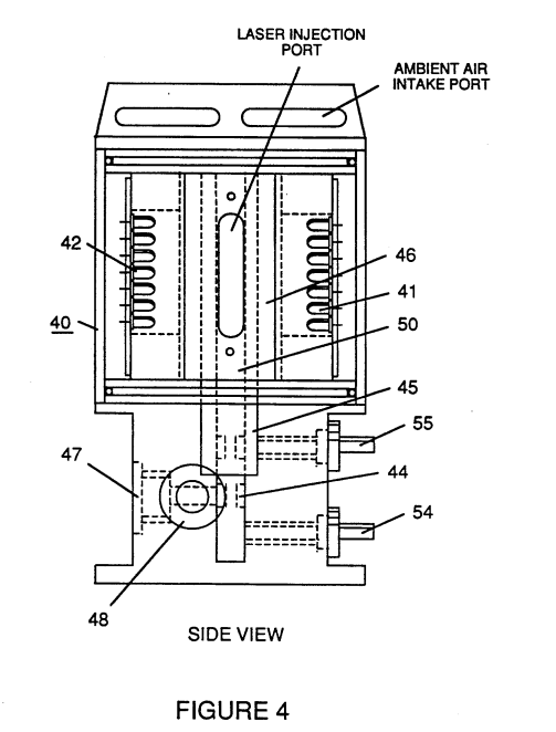
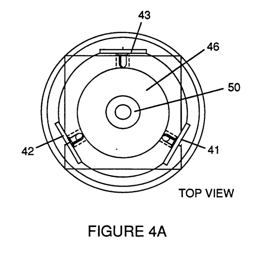
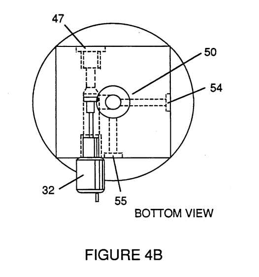
FIG. 5 shows a "quenching conduit" for the safe distribution of a hydrogen fuel in the engine environment, and FIGS. 5A and 5B shows alternative cross section configurations for said conduit.
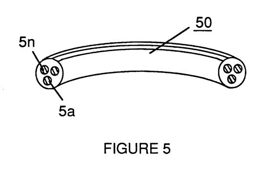
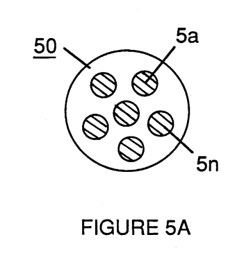
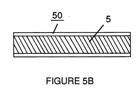
FIG. 6 figuratively represents the modulating effect upon hydrogen gas characteristics of other non-combustible gases included in a fuel gas mixture containing hydrogen in accord with the invention and its fuel gas management system.
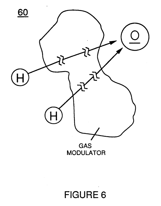
FIG. 7 shows the electron extractor circuit used in the air processor section to ionize and maintain the ionization of introduced air gas.
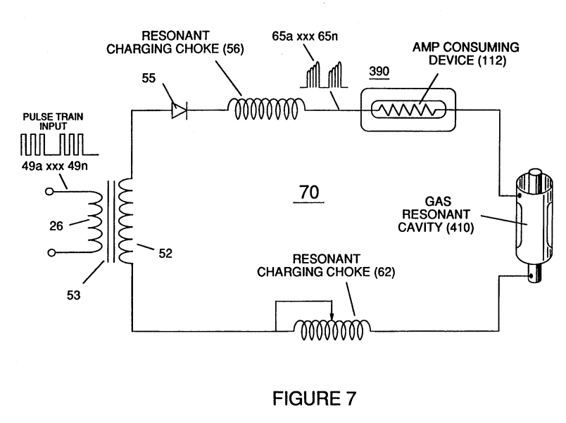
With reference to FIG. 1, it is an object of the invention to regulate a hydrogen fuel gas mixture that is introduced into the engine combustion chamber such that the burn rate of the hydrogen fuel gas remains constant regardless of engine RPM. As used herein, "burn rate" is an arbitrary measure of the relative volatility of a fuel gas (in contrast with the rate at which a given fuel is consumed, e.a., miles per gallon). Thus, it is an object to regulate the combustion "window" of hydrogen in a gas mixture so that optimum combustion is achieved, regardless of engine speed. With reference to Table I, the extreme volatility of hydrogen in the atmosphere (burn rate: 325-265 cm/sec) is shown in contrast with the relatively equivalent burn rates of several known hydrocarbon and fossil fuels (burn rates: 45-35 cm/sec):
TABLE 1:
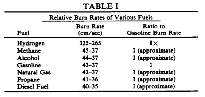
The combustion characteristics and high volatility of hydrogen can be charted with reference to an axis correlated to the running speed of an internal combustion engine, as illustrated by the narrow combustion envelope for hydrogen, shown in FIG. 1 at 1 in contrast with the combustion envelope, for example, in gasoline, 2. Typically, in the tuning of an engine for either optimum performance or efficiency, the low volatility and the wide combustion envelope of a fossil fuel permits an engine to be tuned, for example, to an optimum speed corresponding to 60 MPH, without concern for significant adverse effects or need for adjustment over the remaining engine operating range. The narrow combustion envelope of hydrogen, however, prevents such broad tuning and consequently results in fuel over-enrichment and the engine operation difficulties noted above, passim. In the invention, the burn rate of the hydrogen fuel gas is adjusted to be equivalent to that of a fossil fuel by the introduction into the hydrogen fuel of other non- combustible gases that serve as a modulator of the inherent volatility of the hydrogen.
In addition, the hydrogen/oxygen ratio of 2:1 which represents the optimum combustion ratio for a hydrogen fuel is uniformly maintained in the modulated fuel mixture over the engine operating range, e.g. at speeds represented by 3a, 3b, 3c. The combustion window of hydrogen at a modulated given volatility remains in the same 2:1 hydrogen- :oxygen ratio. Thus, the modulated burn rate of the hydrogen fuel gas, adjusted downward to 43-37 cm/sec, is maintained uniformly in the range of speeds from idling to maximum RPM, in contrast with conventional engine design based on typical gasoline burn rate, which is not usually adjusted. Nevertheless, because of the wide combustion window for gasoline, optimum tuning at 60 MPH as shown at 2 in FIG. 1 will allow satisfactory engine operation to other speeds. In the prior art, use of unmodulated hydrogen allowed engine operation only in the narrow envelope figuratively shown in curve 1. In the invention, a processed gas mixture including a hydrogen fuel component-having a uniform, predetermined volatility is generated by the system and introduced into the engine in a proper mixture to insure optimum combustion throughout the range of engine operating speeds.
FIG. 2 shows a block diagram of a complete hydro- gen gas management system. For explanation and illustration purposes, one cylinder of an engine is shown, however, it is appreciated that adaptations of the system to multiple cylinder engines are within the skill of the art. In the system diagram of FIG. 2, there is shown a conventional reciprocating piston internal combustion engine configuration including piston 1 and cylinder 2 connected to a rod and crankshaft mechanism 3, fuel intake valve 4, exhaust valve 5, and spark plug 6. Valves 4 and 5 and spark plug 6 are operatively interconnected to the management system of the invention.
One aspect of an overall system provides a source of fuel gas including hydrogen, such as a water fuel cell, 7, described in my U.S. Pat. No. 4,936,961 including water capacitor 8 immersed in a volume of water 9 which produces a source of a hydrogen/oxygen and non-combustible gas mixture 10 that is operatively interconnected with the gas management system 11 through regulator 13. Preferably the gas management system 11 includes a logic module and central processing unit interconnected to sensors and controllers in the system. The voltage intensifier-circuit 12 regulates voltage amplitude, pulse frequency and gated pulse frequency associated with operation of the fuel cell 7. (See U.S. Pat. No. 4,936,961, FIG. 1, and U.S. Pat. No. 4,798,661.) and is operatively interconnected to the gas management module. The gas pressure regulator 13 is included proximate the exit orifice of the cell to maintain a consistent back pressure (optimally 15 psi in the preferred embodiment) in the fuel delivery system.
The gas management system logic module 11 deter- mines the mixing of the hydrogen fuel gas mixture 10 produced by the cell with other modulating gases such as ambient air, introduced through manifold 14 and/or exhaust gas introduced through gate 15. The management system module includes inputs from sensors relating to air and engine temperature, engine RPM, gas pressure and the vehicle accelerator or engine speed control 40 which determines the speed at which the engine operates. A distributor control 16, as in a conventional internal combustion engine, determines ignition system function 17 and additionally provides an input signal for a tuned gas meter control 18 that is operatively interconnected to the injector port 19 so that a uniform quantity of modulated fuel gas is injected through valve 4 into the cylinder upon each operating cycle of the cylinder. Air gas processor 20 is also included for treatment of gas derived from ambient air introduced in the system through the intake manifold. (See FIGS. 3, 4, 4A, 4B and discussion, infra.) FIG. 3 illustrates an appropriate mechanical configuration adapted to the overall system shown in FIG. 2.
An intake manifold (not shown) directs ambient air 101 to air filter assembly 31 operatively interconnected to an inlet valve 32 which is regulated by the management module and controls the flow of air into air processor 33 which produces a source of ionized non-combustible gases 102, that in turn may be mixed with non-combustible cylinder/engine exhaust gases 103 introduced at exhaust gate 15. These gases are mixed in the intake manifold 35 with gas from the fuel cell 7, introduced at injector port 19 whereupon the modulated combustion mixture having the hydrogen fuel component in the correct proportion with oxygen is delivered to the cylinder at a burn rate equivalent to that of a fossil or hydrocarbon fuel. An oil inlet port 110 for lubrication is optional. Thus, in the air processor ambient air 101 is ionized and the ionized gas 102, and other modulating 65 gas such as the exhaust gas 103 is mixed until the fuel gas 10 for introduction to the cylinder at the modulated burn rate. Lubricating oil mist is shown at 111.
Appropriate sensors for monitoring air pressure, RPM and engine temperature are operatively interconnected with the management module and controllers regulate various fuel source or fuel gas mixture parameters such as the proportional air mixture introduced in the fuel gas or the proportional exhaust mixture introduced in the fuel gas at respective gates. Idling, low temperature operation adjustments or other calibration adjustments for normal ambient conditions are made by trim pots on other means included in the management module. In a preferred mode, air gas processor shown at 20 in FIG. 2 and in greater detail in FIGS. 4, 4A and 4B is operatively interconnected with a hydrogen fuel cell gas generator operated in accordance with the method of my U.S. Pat. No. 4,936,961. Shape and size of the resonant cavity such as described in my U.S. Pat. No. 4,936,961 may vary. Larger resonant cavities and higher rates of consumption of water in the conversion process require higher frequencies such as up to 50 KHz and above. The pulsing rate, to sustain such high rates of conversion must be correspondingly increased. As noted above in the preferred embodiment of FIG. 2, the pulse generating circuit of the method is interconnected with the management module such that fuel gas is generated by the fuel cell gas generator on demand and such that the fuel cell operation is also responsive to sensed parameters and control signals generated.
Other sources of a hydrogen fuel gas may be used, as well as other types of fuel; the system of the invention manages the combustion characteristics of the engine fuel and the-delivery regardless of source. FIG. 4, 4A and 4B show a side frontal cross-section and plan view from the top and bottom of a type of air gas processor such as 20 shown in FIG. 2. In essence, the processor 40 of FIG. 4 and its operation essentially correspond to the method and apparatus shown and described in my U.S. Pat. No. 4,826,581, (incorporated herein by reference), however, as used in the system of the present invention, the ambient air gases (not the combustible gas produced by the fuel cell), on a reduced scale, are charged and ionized and otherwise enhanced in energy before the ambient air gases are mixed with the fuel gas. In the processor 40 shown in FIGS. 4, 4A and 4B a treatment chamber 50 is provided that encloses a set of batteries 41, 42, 43 of solid state lasers, e.g. 42, a, b, c, d, etc., that are concentrically mounted around a charging cell formed from positively and negatively charged concentric rod 44 and cylinder rod 45 which are connected to an ionizing voltage source through terminals 54 and 55. Optical lens 46 concentrates the laser output to the gas flowing through the processor which also includes outlet port 47 for the energized air gas and a gas meter control 48. The electron extraction circuit 7 ionizes the incoming ambient air gases and consumes the electrons ejected from the gas atoms while the injected laser energy energizes the ionized gases to pre- vent-the processed ambient air gases from reverting back to stable-state, as illustrated by FIG. 7.
In the preferred embodiment of the invention a hydrogen fuel gas mixture is generated by the method of my aforesaid U.S. Pat. No. 4,936,961. That gas comprises a mixture of hydrogen, oxygen and other formerly-entrapped gases dissolved in water. It is the purpose of this invention, beginning with the hydrogen component of a fuel gas, to adapt hydrogen gas to the approximate burn rate of a fossil fuel for use in an internal combustion engine and to maintain the ratio of hydro- gen to oxygen in the mixture at the most efficient 2:1 ratio. The system of the invention modulates the hydro- gen component of the overall gas mixture such that the burn rate of the hydrogen-containing fuel mixture approximates that of a fossil fuel as illustrated in FIG. 1. While the invention of my U.S. Pat. No. 4,936,961 produces a gas mixture including hydrogen, oxygen and all other gases that were formerly dissolved and entrapped in the water from which the hydrogen/oxygen gas mixture released by the process was formed, further modulation of the burn rate of this hydrogen fuel gas mixture occurs in the system of the present invention as a result of mixing with processed ambient air and the water vapor produced as a combustion exhaust product of the engine. In this regard, the rate of gas production in-a water fuel cell (or the introduction of hydrogen per se into the system if a water fuel cell is not used as a fuel source) determines the amount, per se, of hydrogen introduced into the system, but in the manner in which the hydrogen fuel is modulated, mixed with oxygen, and injected in optimal quantities and mixtures into the engine cylinder.
The regulation of the burn rate of the hydrogen fuel, which is of crucial importance in a hydrogen fueled internal combustion engine according to the system of the invention, is determined by the relative proportion of the mixture of the hydrogen containing fuel gas with ambient air or exhaust gas including water vapor that is recycled into the engine. The fuel gas mixture produced by the fuel cell intrinsically includes the optimum 2:1 ratio of hydrogen to oxygen. The mixture of hydrogen and non-combustible gas that modulates the burn rate of the hydrogen fuel mixture to that equivalent to gasoline must be achieved by the addition of the non-combustible gases and maintained uniformly over the range of engine operating speeds. This is accomplished by correlating the rate of fuel gas production from the water fuel cell with the introduction to the gas mixture of other non-combustible gases. This can be accomplished in a simplified engine by manual control involving manually sensed "look, touch and hear" impressions, as well as by complex electronic control means for more sophisticated engines.
Maintenance of-the Consistency of the mixture by the management module prevents overloading of the engine with hydrogen and permits smooth running of the engine regardless of engine RPM or power load. The distributor and ignition system operates in a conventional mode to provide spark ignition of the fuel and oxidant mixture in the cylinder at the appropriate time in a piston reciprocating cycle that is otherwise also related to fuel intake and exhaust outlet sequences in the cycle. In the invention, however, two aspects of the injection of the fuel gas mixture into the cylinder at the intake cycle are controlled: (1) the 2:1 proportion of hydrogen to oxygen to "non-combustible" gases in the fuel intake mixture is maintained at a predetermined proportion such that the "burn rate" is maintained at the lowered predetermined rate corresponding to that of a fossil fuel; and (2) the quantity of the fuel mixture introduced to the cylinder at the intake of the cycle is the same per cycle regardless of engine RPM. Thus, although the rate of hydrogen production by the fuel cell must increase with higher engine RPM, the consumption of hydrogen, per cycle, remains constant. This constancy is maintained by the tuned gas meter control 18, 19 and by variation of the rate of gas production in the fuel cell as controlled by the gas management system CPU, 11.
The gas meter control which provides the uniform delivery of the fuel gas mixture is determined by pulse signals generated by the distribution corresponding to each cycle of the engine. FIG. 6 represents the modulating effect on hydrogen density in a gas mixture, that the other large (non-combustible) gas molecules have in the hydrogen fuel gas that is accomplished by the invention. To wit, other gases dilute the hydrogen concentration in a given volume; the dilution in turn reduces the burn rate of the hydrogen per se component and enables the burn rate of the overall fuel gas mixture produced by system to approximate that of a fossil hydrocarbon fuel. As this modulation of the burn rate occurs, however, it is necessary to maintain the overall ratio of hydrogen to oxygen in the mixture as close to 2:1 as possible to prevent over-enrichment of the hydrogen in the fuel and the consequent shut down problems that result from an excess of hydrogen.
Thus, inert water vapor exhaust gas, (e.g., from valve 5 in FIG. 2), as well as ambient air, is used as a dilutent. The introduction of ambient air may result in a proportional excess of oxygen in the mixture over the preferred ratio; however, excess oxy- gen insures complete combustion of the hydrogen component; to the extent that oxygen is in excess, it is a non-combustible dilutent. Too much of an oxygen excess may result in the production of undesirable NOx exhaust gases; however, this is not a significant problem and may be resolved in the engine system of FIG. 2 by the introduction of more exhaust gas rather than air as a dilutent. When the burn rate of hydrogen is, however, reduced to that of a fossil fuel, the production of nitro- gen oxides is reduced because the combustion temperature and rate is reduced. Sensors of the system of FIG. 2 monitor air pressure and temperature which affect the dilution of the hydro- gen fuel.
The management module CPU and controllers appropriately adjust the gas mixture components to maintain a uniform burn rate for the fuel mixture regardless of engine speed. For example, if the burn rate is not maintained at a constant, the introduction of additional hydrogen by throttling the engine would disrupt the narrow combustion window of the gas resulting in engine inefficiency, roughness or shut down because of the over-enrichment. Distribution of the hydrogen gas (or the fuel gas mixture produced by the means of my aforesaid Letters Patent) within the engine system may be accomplished by an appropriately configured circuit of "quenching tubes", such as are shown in FIGS. 5 and 5B. The quenching tubes comprise a conduit of discrete small volumes such as formed in an open cell porous material formed in an otherwise solid, extending member.
Typically, a plurality of conduits of microcell type material from 0.015 to 0.025 inch in diameter may be formed in a solid length having an outer diameter of approximately 0.378 inch in the manner shown in FIG. 5. The conduit size specified is appropriate for a fuel gas having a burn rate equivalent to gasoline. Conduit diameters may be proportionately larger or smaller if the hydrogen concentration is further diluted or increased. The quenching tube prevents burn-back or flash-back of hydrogen in its delivery tube. Flash-back, a serious problem in conventional hydrogen gas transport systems, is eliminated by the quenching circuit tubes of the invention. In the control system of the invention, all parameters are adjusted to maintain a uniform burn rate of the hydrogen containing fuel gas, which is the key to smooth engine operation. In the mechanical system shown in FIG. 3, the characteristics of the hydrogen fuel are modified to adapt to load conditions, and the system works in a manner comparable to that of a conventional carburetor in a fossil fueled engine.
When used with a water fuel cell and the method of my aforesaid U.S. Pat. No. 4,936,961, a preferred management system includes a pulse generator for fuel gas production and includes a phase lock loop circuit that detects and scans a resonant frequency in the fuel cell generator and maintains that frequency. From the foregoing description of the preferred embodiment, other variations and modifications of the system disclosed will be evident to those of skill in the art.
CLAIMS:
1. A management system for a fuel gas mixture containing hydrogen that is introduced as a fuel to an internal combustion engine consisting of:
- means for monitoring the composition of a fuel gas mixture introduced into the engine such that the proportion of hydrogen to oxygen in the mixture is approximately 2:1; and
- means for modulating the density of the hydrogen component of the introduced fuel gas mixture by the addition of other non-combustible gases to the mixture such that the burn rate of the fuel gas mixture approximates that of a fossil fuel.
2. The system of claim 1 in which the means for modulating includes a means for the mixing of a proportion of the exhaust gas of the engine into the fuel gas mixture introduced into the engine.
3. Apparatus for the distribution of a fuel gas mixture containing a hydrogen gas component comprising a plurality of longitudinally extending conduits having an internal diameter of 0.015 to 0.025 inch intrinsically formed in an otherwise solid matter
4. The apparatus of claim 3 in which the conduit comprises a porous open celled foam.
5. A process for maintaining combustion in an internal combustion engine that is fueled by a fuel gas mixture containing hydrogen that is introduced as a fuel to consisting of:
-
monitoring the composition of a fuel gas mixture introduced into the engine such that the proportion of hydrogen to oxygen in the mixture is approximately 2:1;
-
modulating the density of the hydrogen component of the introduced fuel gas mixture by adding other non-combustible gases to the mixture such that the burn rate of the fuel gas mixture introduced to the engine approximates the burn rate of a fossil fuel; and
-
Maintaining the volume of the introduced fuel gas mixture at a predetermined quantity for each operating cycle of the engine, regardless of engine operating speed
6. The process of claim 5 in which the step of modulating includes mixing a proportion of the exhaust gas of the internal combustion engine into the fuel gas mixture introduced into the engine.
7. The process of claim 5 including the step of ionizing ambient air gases and introducing said ionized gases to the fuel gas mixture.