# VIC5 Toroidal Core
# Linear Magneto Effect
# 2014 Stan Meyer Conference Notes on Linear Magnetism
> Analysis and speculation on the comments regarding Linear Magnetism, given by Max during the 2014 Stan Meyer Conference. This discussion focuses on the VIC5 core and the step-charge behavior.
1. The voltage reference to the cell must be biased above 0V Arbitrary Ground.
- Max: There's many ways to bias the voltage
- Max: can bias his B+ supply up to +600VDC
- Max: As long as the wave is above 0V, you will make hydrogen
- Max: When the wave levels off, no increase in hydrogen will continue. You've reached the peak voltage potential of your cell.
2. No specific waveform will make more bubbles over another, until the secret is found, and you get an eruption in front of your face.
3. The first pulse causes the voltage reference to shift below 0V. The reason for the dip below zero is the secret to Stan's effect.
- Max implied a spectator comment was "on the right track":
- "Give it the positive and nature will provide the negative energy to balance it automatically."
-
4. A really good scope is required.
- What is it about the scope?
- The HV isolation is relatively the same as our external isolated probes.
- The Techtronics scope may be able to use actual ground as a reference for the 0V line.
- Audience: An automotive scope designed for watching spark waveforms can reveal the wave operation.
- This confirms a focus on the transient period
5. Russ is Nuts -
- Demonstrates the Linear Magneto Effect, discovered by Ed Leekskalin and his [Perpetual Motion Holder](https://physics.stackexchange.com/questions/167356/ed-leedskalnins-perpetual-motion-holder-pmh)
- Linear Voltage holds nuts together
- Snap it with a backEMF (dead short a battery into a field around it)
**Linear Magnetism Statements:**
1. Linear Magnetism travels in a circle, in the same direction, forever
2. No voltage reversal exists
3. In the VIC5 core, linear magnetism travels in one direction only
4. There is no backEMF in the VIC5 toroid
**David**:
- A threshold of 201mA was found (in a given setup?) where electromagnetism overtakes linear magnetism.
Changing the Resonant Frequency of a coil
- **Max:** An automotive ignition coil has a resonant frequency around 50Hz
- The car coil is already a well designed resonant transformer
- **Max**: That resonant frequency can be changed by introducing a Gate frequency
- The gate interrupts the core and allows the pulses to come through
- **Max**: Changing the gap in the core
- anywhere up to 500kHz
- with a step charge coming off of it
Magnetic Amplifiers
- Used in legacy computer technology
- core materials that can saturate are exploited and used for a binary on/off state.
- Pickup coils were wound around the toroid to "check" the state of the bit
- The pickup coils do not load the toroid and dampen the linear magnetism
- Toroids can be saturated and will retain the linear magnetism indefinitely.
Back EMF
- **Max**: Every time you capture the backEMF, you're going to grow a step, and you end up with a ramping wave.
The cell will continue to produce hydrogen for up to 1 minute during offtime
The 8XA does resonate - I will eventually prove it
Relationship of the tube sizes.
- **David Puhcta**: The volumes of each tube's metal is relevant
- An imbalance exists with the mismatched sizes
- The positive outer tube was floated above the negative one
- The negative tube has a strong secure mounting base
#### Further speculations from known results:
The pulse waveform contains an ON time width that is small enough to effect a modulation into the inductor core.
The pulse train exists to induce the linear magnetism into the core. The gate period allows it to continue traveling with minimal dampening by the secondary coils and cell load.
The Stan effect is not to **avoid** saturation of the VIC5 core, but to **sustain** it! Using only the minimum amount of energy required.
The pulse amplitude can reach the voltage breakdown of the cell's gap.
# Magnetic Amplifiers
# THE MAGNETIC AMPLIFIER
By [George Trinkaus](https://www.nutsvolts.com/magazine/contributor/george_trinkaus) [View In Digital Edition ](http://nutsvolts.texterity.com/nutsvolts/200602/?folio=68)
## A LOST TECHNOLOGY OF THE 1950S
***Anyone can build it!***
Most folks believe that first came the vacuum tube and right on its heels came its successor, the transistor — an historical fact, correct? Not really. Another competitive control technology developed by US and Nazi engineers came in between. It was the magnetic amplifier. Rugged, dependable, EMP-proof, and capable of handling greater electrical powers than either transistor or tube, the magnetic amplifier is a simple device that can be built by anyone.
By the 1950s, the magnetic amplifier was not just an experimental dream languishing in some inventor’s notebook. Nor was this ingenious technology sitting unexploited in patent archives. The mag amp was in manufacture in a number of versions and had a clique of boosters, including many electronics engineers, especially within the US Navy.
The mag amp is an American invention and has been used in heavy electrical machinery regulators since 1900. In the 1940s, the Germans took the American’s relatively crude device, assigned their best scientists, invested millions, and developed it into a faster, lighter electronic tool competitive with the vacuum tube in performance but more simple and dependable. It’s also much more rugged. A mag amp can be made to be nearly indestructible.
The Germans used the mag amp in electric brakes for trucks, streetcars, and locomotives. They used it for high-voltage utility-power controls and even for early computers.
Appreciating its indestructibility, the Nazi military used it in gun stabilizers, in automatic pilots, and in missile-guidance, including the rocket stabilizer and steering systems of the V-2.
After the war — like German rocketry itself — the mag amp emigrated to the US, where it got further development by enthusiastic American engineers. By 1951, a Navy engineer could write, “Electronics engineers are now forced to concede recognition of the magnetic amplifier, as it has demonstrated its value beyond question in many fields dominated by the electron tube.”
## SIMPLICITY
The mag amp, like the vacuum tube and transistor, is an electrical control valve. When a smaller circuit controls another circuit’s larger flow, that’s the definition of an “amplifier.”
A mag amp can be put in series with any circuit carrying an alternating current and control that flow. No external power supply is required to run the device. The simple mag amp is just a core of iron or ferrite with some coils of wire wound around it.
One other basic component is the rectifier. Today, rectifying diodes are compact, easily available, and cheap. The old selenium rectifiers used back in the 1950s were large, cumbersome, and expensive.
A variety of ferrite core materials are also available to today’s builders.
With some spools of wire, a ferrite rod, and a couple of diodes, you can throw together a little high-frequency mag amp on a Sunday afternoon.
Compare the construction challenge of a vacuum tube or transistor. And the mag amp can handle voltages and currents that you would never put into the average transistor or tube.
## HOW IT WORKS
The mag amp is a sort of variable choke. It controls the impedance (opposition) to alternating current in a coil by controlling the magnetic condition of the core on which the coil is wound. This is done by energizing another winding on the core called a control coil. Depending on the energy in the control coil, the core’s permeability (its receptivity to magnetism) can be varied by degrees, thus controlling a larger AC flow.
Fully energized, the control coil can reduce the permeability of the core to zero, in which case the core is said to be saturated. Then it becomes so magnetically unresponsive it’s like the core has been removed.
[](https://www.nutsvolts.com/uploads/wygwam/NV_0206_Trinkaus_FIG01.jpg)
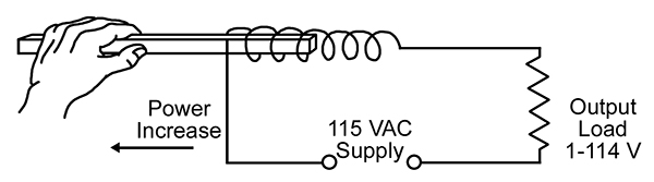
**FIGURE 1.** Principle of Oeration.
---
**Figure 1** is a way of showing the principle. With the core completely within the coil, the impedance to the flow is high, permitting perhaps only a fraction of a volt to appear across the load. Pulling the core out causes the load voltage to rise progressively to 115. Since it took only a few watts of muscular energy to move the iron core within the coil, which may, in turn, control several horsepower, the device is an amplifier.
[](https://www.nutsvolts.com/uploads/wygwam/NV_0206_Trinkaus_FIG02.jpg)
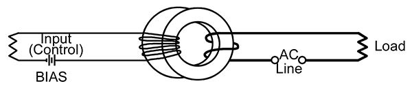
**FIGURE 2.** Saturable Reactor.
---
**Figure 2** is another demonstration. This qualifies as a saturable reactor. This circuit could be for a dimmer for theater stage lighting. Add a diode, and you have a basic mag amp (see **Figure 3**). The larger coil is the control coil. The smaller is called the loading coil.
[](https://www.nutsvolts.com/uploads/wygwam/NV_0206_Trinkaus_FIG03.jpg)
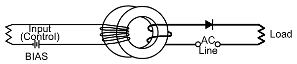
**FIGURE 3.** Mag Amp.
---
The diode rectifier makes the load current unidirectional, which assists the control winding in saturation. Considerably less power is now required, making it a more potent amplifier.
This mag amp, however, will function as a step-up transformer, which would be undesirable since it would send energy back into the control circuit. This effect is cleverly cancelled by running the AC through a pair of parallel loading coils which are wound in opposite directions.
[](https://www.nutsvolts.com/uploads/wygwam/NV_0206_Trinkaus_FIG04.jpg)
**FIGURE 4.** Functional Mag Amp.
---
**Figure 4** is your basic functional mag amp represented by the appropriate schematic symbols. The control coil symbol is a single sharp angle-line, but the control coil actually has many more turns than the loading coil.
How many turns? The rule of thumb is control-coil ampere-turns equals loading-coil ampere-turns plus sufficient extra turns to saturate the core. (Much of the how-it-works above is from *Magnetic Amplifiers* by the US Navy, 1951, recently republished.)
## USES
The mag amp still has industrial uses in the control and regulation of power utilities and big electric motors, as in locomotives, but its most fascinating applications — mostly forgotten — are in electronics.
The mag amp can modulate, switch, invert, convert, multivibrate, audio-amplify, radio-amplify, frequency-shift, phase-shift, and multiply. Stages can be cascaded. Simple feedback techniques enable gains in the millions.
The mag amp can even compute. Trouble-proof magnetic binaries replaced the less reliable vacuum tubes used in some early digital computers.
[](https://www.nutsvolts.com/uploads/wygwam/NV_0206_Trinkaus_FIG05.jpg)
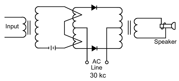
**FIGURE 5.** Mag-amp Audio Amplifier (push-pull).
---
**Figure 5** shows the incredibly simple circuit for a mag amp audio amplifier.Mag-amp audio would be a challenging pursuit for some adventurous audiophile. But the mag-amp electronics which engaged this writer is in radio.
## MAG AMPS IN RADIO
The first patent for a mag amp was in 1903, but little attention was paid until 1916 when radio pioneer E.F.W. Alexanderson seized on the idea as a means of controlling the giant rotary alternators he was using for high-power radio transmitting (at 10,000 to 100,000 cycles). The *Magnetic Amplifier Bibliography* (by the US Navy, 1951) lists three Alexanderson patents in 1916 and three more in 1920, the last titled “Transoceanic Radio Communication.”
[](https://www.nutsvolts.com/uploads/wygwam/NV_0206_Trinkaus_FIG06.jpg)
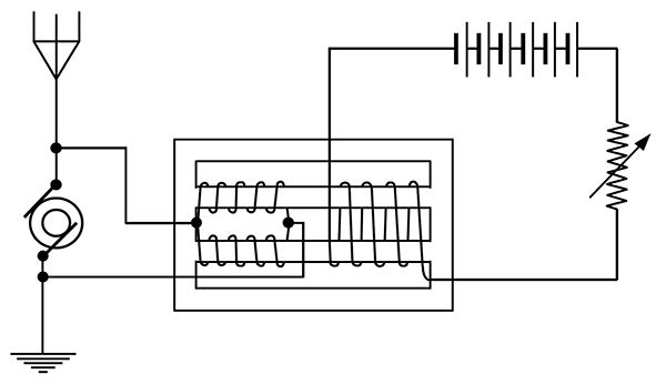
**FIGURE 6.** GE Mag-amp Modulator by Alexanderson.
---
The mag amp can turn the alternator on and off for telegraphy and vary the signal for speech modulation (see **Figure 6**).
The frequency limits of an alternator are low, so the mag-amp was reinvented in that era as a frequency multiplier (doubler, tripler), as seen in **Figure 7**. The *Bibliography* cites many radio-transmitter frequency-multiplier patents up through the 1920s. These are simple circuits compared to those of vacuum-tube frequency changers that came later.
[](https://www.nutsvolts.com/uploads/wygwam/NV_0206_Trinkaus_FIG07.jpg)
**FIGURE 7.** Frequency Multiplier.
---
Early mag amps with solid iron cores never got above a few hundred kilocycles. Powdered-iron cores, the ceramic-iron-oxide composition known as ferrite, and later the ultra-thin magnetic tapes liberated the mag amp, so by the 1950s the limit was up to a megacycle and switching rates were in microseconds, suitable then for computer applications. Techniques for the modulation even of microwave frequencies were also developed in the 1950s (see **Figure 8**).
[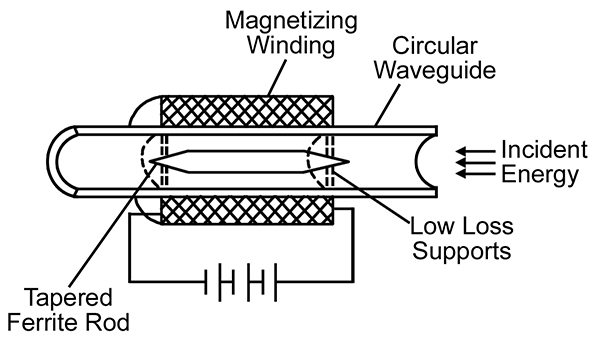](https://www.nutsvolts.com/uploads/wygwam/NV_0206_Trinkaus_FIG08.jpg)
**FIGURE 8.** Microwave Mag Amp.
---
## MY HOME-BUILT MAG AMP
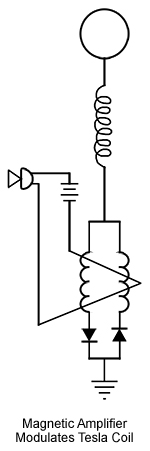
I wanted to see if a mag amp could modulate a Tesla coil (see **Figure 9**), as Alexanderson modulated his big alternator-transmitter. I used the schematic in **Figure 4**. The Navy booklet, *Magnetic Amplifiers* served as a reference.
[](https://www.nutsvolts.com/uploads/wygwam/NV_0206_Trinkaus_FIG09.jpg)
**FIGURE 9.** In Tesla Coil Circuit.
---
I first obtained a ferrite rod (material #33), six inches by just under 1/2-inch diameter. I got it surplus from Alltronics, for about $5, but it’s no longer available, though they do carry a four-inch version (**[www.alltronics.com](http://www.alltronics.com/)**.) Another source for rods is Surplus Sales of Nebraska (**[www.surplussales.com](http://www.surplussales.com/)**). From Alltronics I also got spools of magnet wire — #26 for the two loading coils and #30 for the control coil.
I wound my coils, not directly on the ferrite, but on acrylic tubing, 1/2 inch inside diameter (from Tap Plastics), which I could slip over the rod. A section of the tubing and a couple of nylon fender washers from the local hardware store made a well insulated spool or coil form on which to wind the coils on my winding jig. The loading-coil spools were 1-1/8 inch wide, the control coil two inches wide. For the loading coils, I wound 13 layers, 860 turns of the #26 wire, laying on some electrical tape for extra insulation between each layer. I wound the two loading coils in opposite directions. The control coil took 400 feet of the #30 wire.
A mag amp is frequency specific according to the size of its loading coils. (Thus, an audio amp would be quite large.) I wanted 180 kilocycles, and I determined the number of turns experimentally.
For the rectifiers, I used eight 1,000-volt, three-amp 1N4008 diodes, four in each leg (All Electronics, **[www.allelectronics.com](http://www.allelectronics.com/)**). The mag amp was now safe to 4,000 volts and could handle the output of my solid-state Tesla coil.
## PERFORMANCE
So that I could observe the mag amp’s performance with my signal generator and oscilloscope, I replaced the 1N4008s with two low-power signal diodes. In series with the control coil, I put a 12-volt battery and a telegraph key, as a convenient switch. The mag amp is frequency-specific; you design it for a particular range. Keyed on and off, the mag amp showed response from 155 to 200 kilocycles (a range that happens to fall within the license-free experimental radio band called LowFER).
What a versatile device! At a particular frequency, operating the key would increase or decrease the amplitude of the wave as traced on the scope. At another frequency, the keying would shift the frequency back and forth, and at another it would shift the phase.So this one little device, depending on how it was tuned, could do on-off keying (CW), amplitude modulation (AM), frequency-shift keying (FSK), frequency modulation (FM), or phase-shift keying (PSK), including bi-phase-shift keying (BPSK), which is a common mode of digital transmission. Placed in the ground circuit of my solid-state Tesla-coil, the little mag amp showed that it could do all of the above with more than 3,000 oscillating volts running through it. This would be quite a task for a vacuum tube and probably beyond any transistor.
And I built it myself. **NV**
# VIC5 Winding Machine
This machine was designed to allow easy winding of VIC5 replica bobbins. Ferrite U-Cores (approx. 2000 perm) were purchased that matched Stan's original dimensions. The STLs are provided for free if one desires to make these coils. Please understand that if you cannot afford cores to go inside, do not build this. Testing results using these cores will be provided for free at a later date.
YouTube video for machine overview:
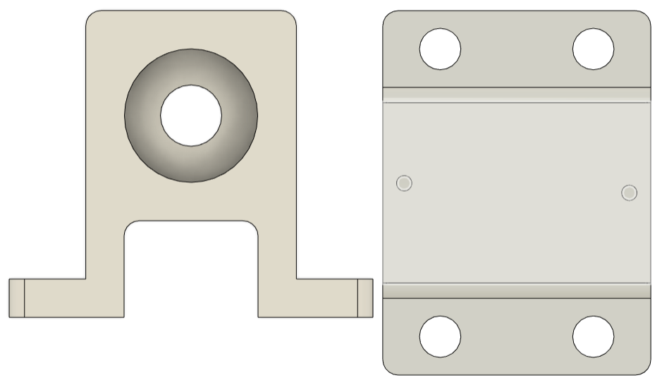
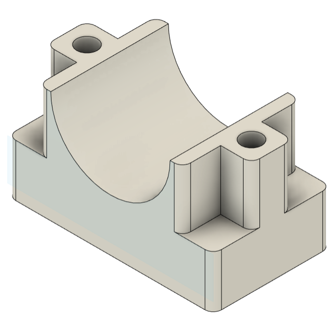
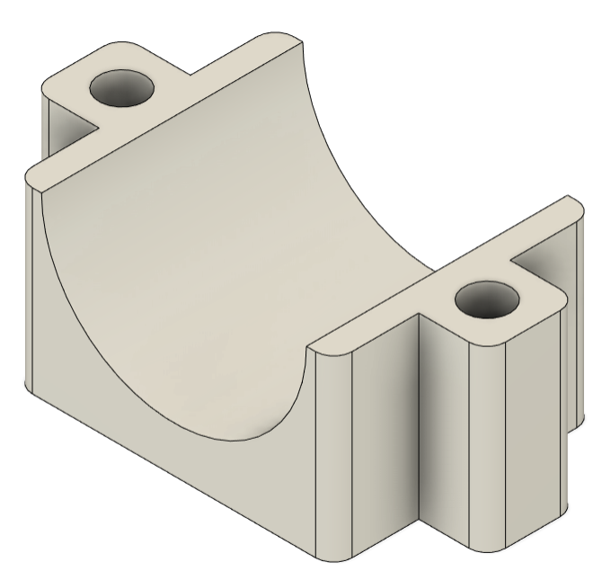
##### Bearing Blocks:
[Bearing Blocks.stl](https://stanslegacy.com/attachments/242)
##### [](https://stanslegacy.com/uploads/images/gallery/2023-10/nyAj7bnV6CgDdALz-image-1696463381483.png)
##### Bottom Motor Mount:
##### [Bottom Motor Mount\_.stl](https://stanslegacy.com/attachments/243)
##### [](https://stanslegacy.com/uploads/images/gallery/2023-10/YOyTLfsT1ZILaPVE-image-1696464275823.png)
##### Top Motor Mount:
##### [Motor Mount Top\_.stl](https://stanslegacy.com/attachments/244)
##### [](https://stanslegacy.com/uploads/images/gallery/2023-10/Lm8Rp1vRizgv41Te-image-1696464321838.png)
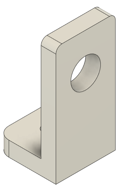
##### Inductive Sensor Mount:
##### [Inductive Counter Holder\_.stl](https://stanslegacy.com/attachments/245)
##### [](https://stanslegacy.com/uploads/images/gallery/2023-10/xcnWeBSa50zDLZ0C-image-1696464372078.png)
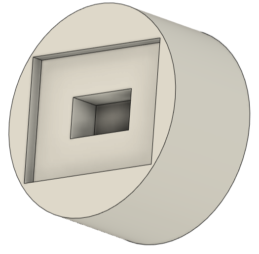
##### Bobbin Ends
[VIC5 winder end caps\_.stl](https://stanslegacy.com/attachments/246)
[](https://stanslegacy.com/uploads/images/gallery/2023-10/nwDyTdVCcqxvKdOb-image-1696466140549.png)