Custom Waveform Generators
- The Dave Lawton 9XA
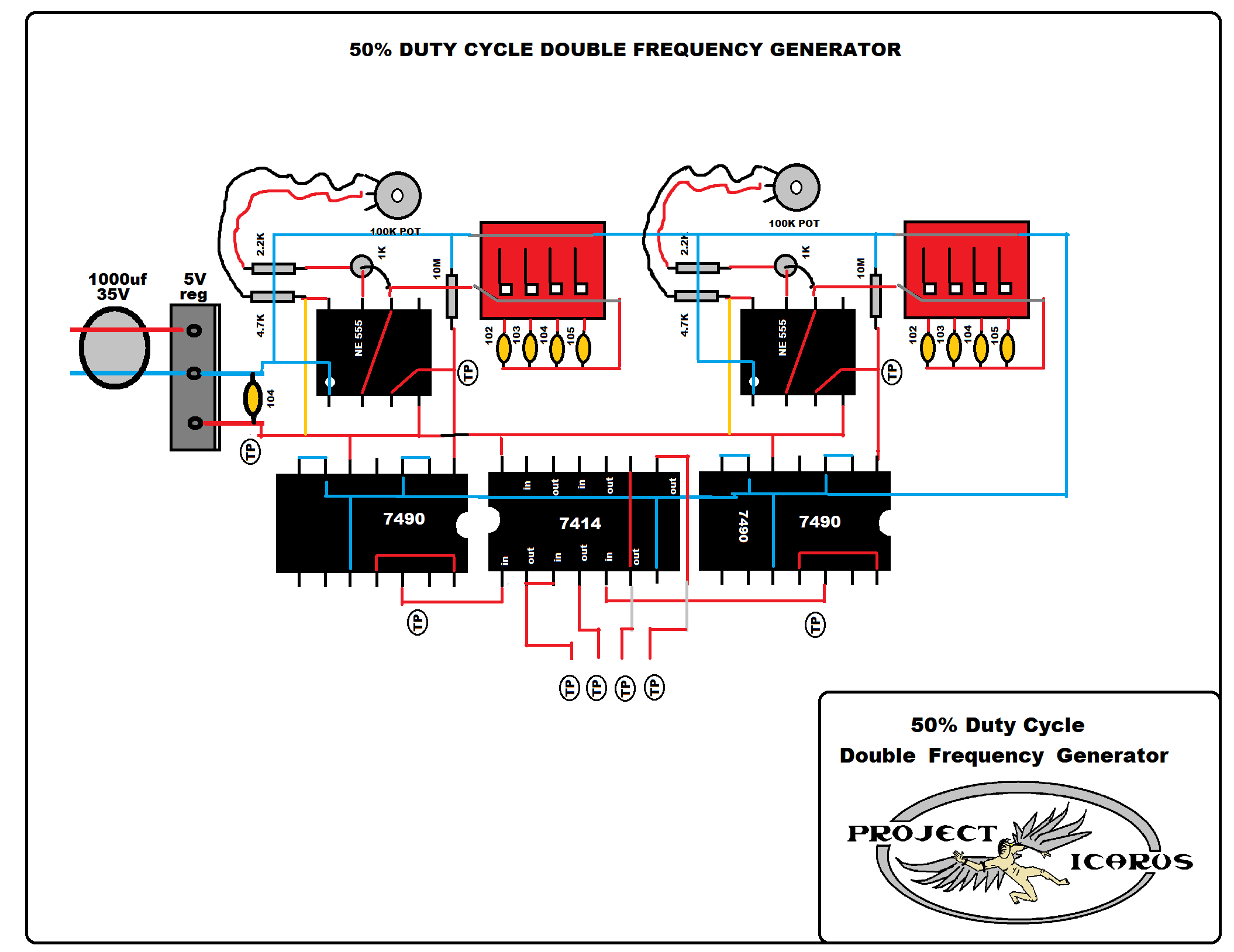
- 50% Duty Cycle Double Frequency Generator
- Adjustable Duty Cycle Gated Pulse Frequency
- 9XA Method
- 2 Arduino - Dual Channel - Triple AND Gate (Perfect Pulse Driver)
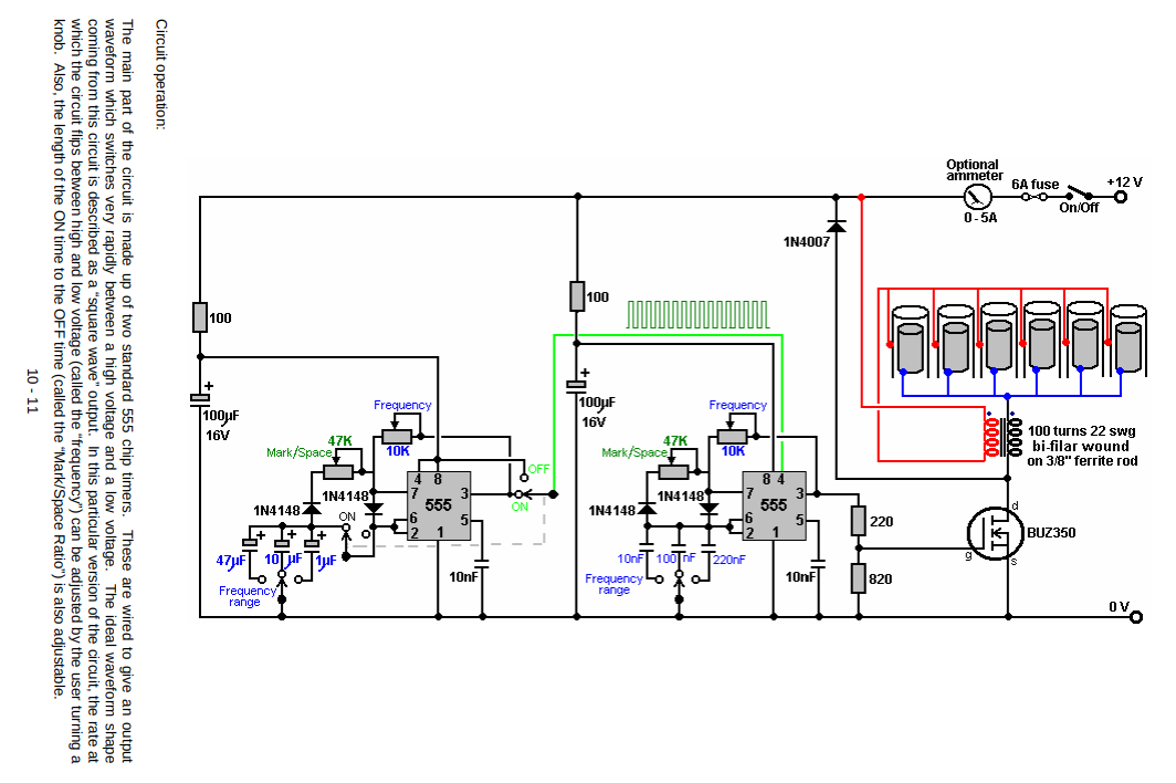
The Dave Lawton 9XA
Source: http://quanthomme.free.fr/qhsuite/2011News/imagenews11/MeyerReplicatAnglais29pages.pdf
The Dave Lawton 9XA is a versatile pulse and gate generator with variable duty cycle on both 555 timers.
One design note that exists here, is that Pin 3 Output of timer 1 is used to provide Vcc power to Pin 4 on Timer 2. This means an inherent latency is always introduced by the 1st RC charge cycle to power up the 2nd timer. This would cause a partial leading pulse. Other than that issue, it's a pretty solid circuit.
Using a BUZ350 mosfet to pull down the B+ 12V through the cell and negative choke.
50% Duty Cycle Double Frequency Generator
PDF Download: http://irondmax.com/pdf/ProjectIcarus.pdf
|
50% Duty Cycle Generator |
 |
|
50% Duty Cycle Divide X 10 |
 |
|
Gated Frequency |
 |
|
Signal Inverter |
 |
|
5 Volt Regulator |
 |
|
Clock Pulse Generator |
 |
Adjustable Duty Cycle Gated Pulse Frequency
One can use a 555 with two 1N4148 diodes to allow independent control of duty cycle ON/OFF times. Each diode has a 100k 10-turn precision potentiometer placed in series to capacitor as shown below. Rotary switch for selection of different capacitor values can allow frequency range selectivity. "RA" below can be a potentiometer to allow for frequency adjustment.
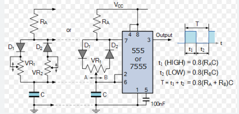
Photo from Electronic Tutorials: Electronic Tutorials (555)
In the build below, pin 3 of 555 was also output to CD4017 decade counter stage to produce a gate. This provided clock synchronization, and only allows 5 pulses per gate ON time. Otherwise, any independent driver of CD4017 would produce clock drift and not allow a discrete number of pulse per gate ON time. Beauty of shift registers in 4017's is even though a 1mS ON time may be occurring, the whole period will be used to divide by 10. Thus maintaining a 50% gated pulse time if desired. Both the adjusted pulse train from Pin #3 and output of CD4017 (Pin #12) is put into inputs (Pin #1 and Pin #2) of a 7408 AND logic gate chip. Pin #3 on 7408 is output, which is shown in yellow below on scope. Circuit driver side isolation may be achieved with H11D1 similar to the 9XA.
Gate can be adjusted by RA resistor to produce increase occurrences of pulse train
Pulse duty cycle ON time, down to lowest, measured at 1mS.
Adjustable Gated Pulse Freq Gen
This method allows pulse duty cycle control, and synchronized gate to pulse train.
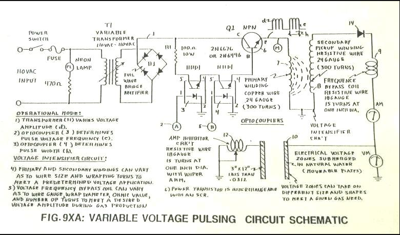
9XA Method
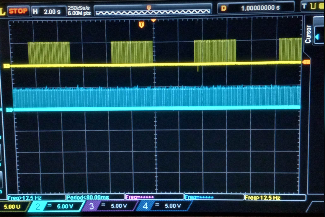
The 9XA was a circuit that Stan used to produce a gated pulse frequency via two H11D1 optocouplers. The optocouplers were driven by two independent stages of 555 timer clock frequency into 3 7490 decade counter ICs. The 7490s provided divisions of 555 frequency, but also produced 50% duty cycle pulses. Below, "A" is one 555/7490 stage and "B" is second 555/7490 stage. The two optocouplers produce an equivalent to AND logic gate.
Figure 1: 9XA schematic
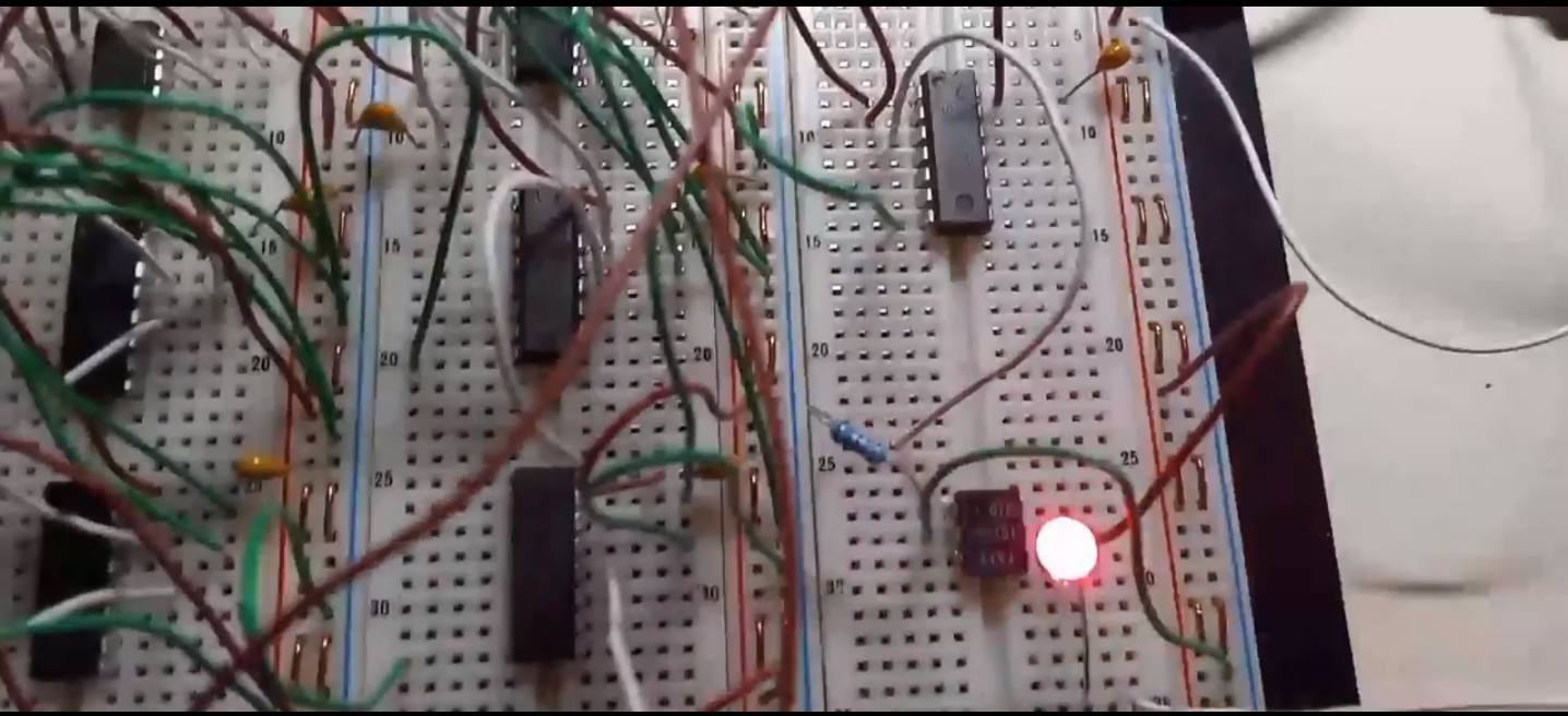
Below is an 9xa scope shot, showing how two independent 9XB style frequency generator's outputs were used to trigger two H11D1 optocouplers to produce a gated pulse train as shown in schematic. In this setup, I had 555's produce a 100khz output to 4 CD4017 dividers. This allowed a 10khz with 50/50 duty cycle to be achieved. LED is just for visual confirmation. If looking closely, you can see how the gating generator isn't synchronized with frequency generator. This causes extra pulses to arise during gated ON times, also called "clock drift".
NOTE: CD4017s were used in place of 7490s, they accomplish the same task with less wiring required.
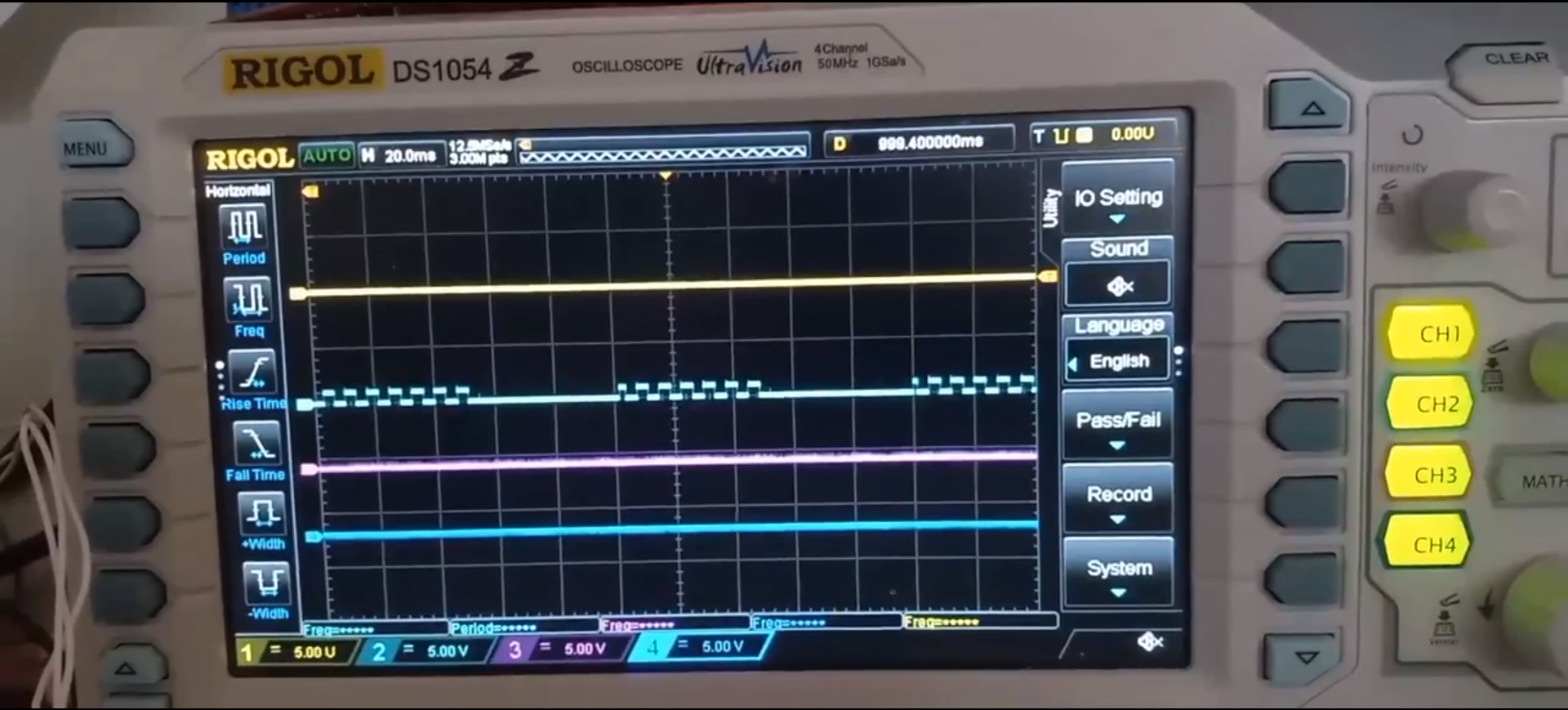
Video Link: 9XA Circuit Waveform
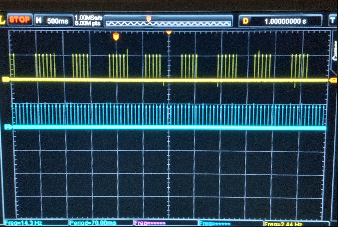
2nd setup had a modification where both signals from 555/CD4017 were fed into an 7408 AND logic gate. This produced the waveform seen below. In this instance, only 1 H11D1 optocoupler was required.
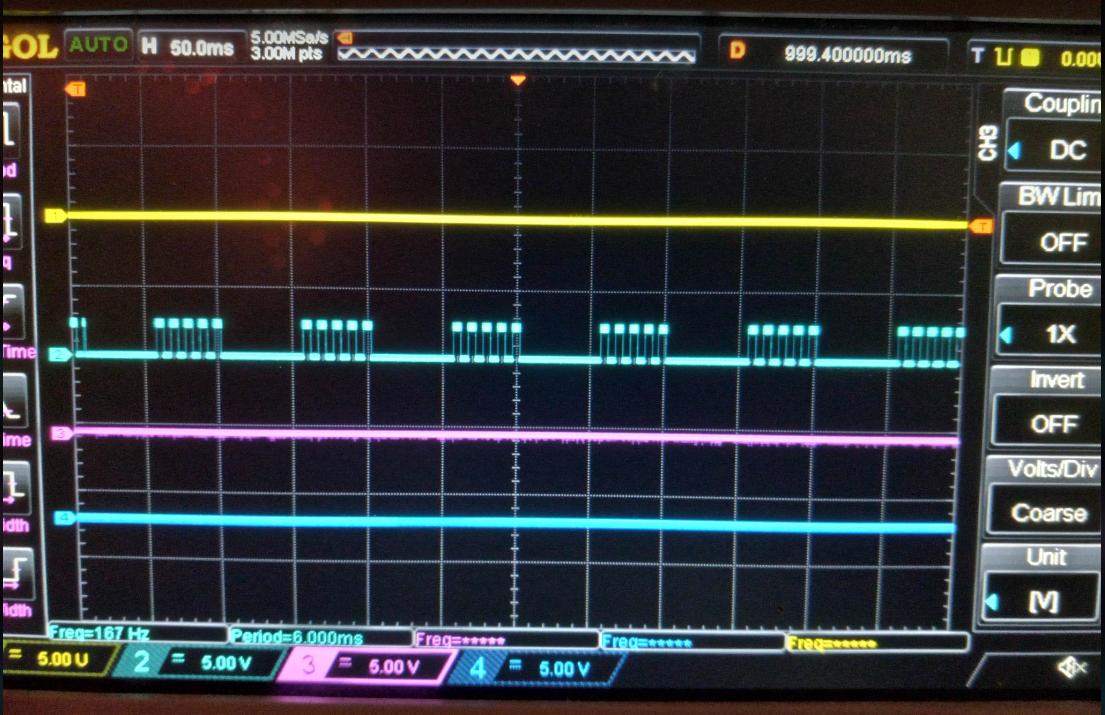
LED providing visual verification of pulse waveform.
Video Link: 9XA, 7408 mod
9XA does provide a 50% duty cycle pulse frequency with a 50% duty cycle gate frequency. However, clock drifting is an issue if both waveform generators are used independently. If both decade counter stages are driven from same 555, a synchronized clock can be achieved. It is unclear if Stan synchronized with one 555.
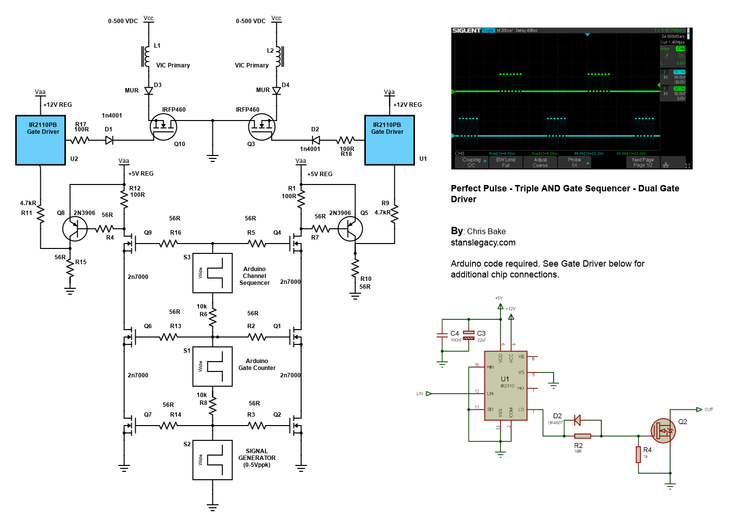
2 Arduino - Dual Channel - Triple AND Gate (Perfect Pulse Driver)
By: Chris Bake
Arduino Code: https://bitbucket.org/cbake6807/dualtripleseq/src/master/
Parts List
- External Signal Generator: 0-5Vppk output.
- Power Supply: ATX is ideal, providing +5V REG and +12V REG.
- 2N7000 Signal MOSFETs: Quantity 6.
- IRFP460 or Similar Power N-channel MOSFET: Quantity 2.
- 56Ω 1/8W Resistors: Quantity 10.
- 100Ω 1/2W Resistors: Quantity 2.
- 4.7kΩ Resistors: Quantity 2.
- 2N3906 PNP General Purpose Transistor: Quantity 2 (can be substituted with any general PNP transistor).
- IR2110PB Gate Driver Chip 14-pin: Quantity 2.
- Arduino Nano (or similar): Quantity 2 (must support hardware PCNT).
- Rotary Encoder: Quantity 1.
Software Requirements
- Arduino IDE: Ensure it is installed and updated to the latest version.
- Encoder Library: Install via the Arduino Library Manager.
Arduino Setup
Pulse Counter Arduino
-
Upload Script
- Open the Arduino IDE.
- Connect the first Arduino (PulseCounter) to your PC.
- Open
PulseCounter.inofrom the provided file. - Upload the script to the Arduino.
-
Connect the Encoder
- Connect the encoder's VCC to the Arduino's 5V pin.
- Connect the encoder's GND to the Arduino's GND pin.
- Connect the encoder's CLK and DT pins to two digital pins on the Arduino D2 and D3.
- Connect the encoder's Button pin to D5.
-
Verify Encoder Output
- Open the Serial Monitor in the Arduino IDE.
- Rotate the encoder and check the output to confirm it is functioning correctly.
Adding a Pushbutton for Sync Mode Toggle
Parts Required
Hardware Connections
-
Connect the Pushbutton
- Connect one terminal of the pushbutton to the Arduino's 5V pin.
- Connect the other terminal of the pushbutton to digital pin 4 on the Arduino.
-
Add a Pull-Down Resistor
- Connect a 10kΩ resistor between digital pin 4 and GND. This ensures that the pin reads LOW when the button is not pressed.
Summary of Connections
Sequencer Arduino
- Upload Script
- Disconnect the PulseCounter Arduino and connect the second Arduino (Sequencer) to your PC.
- Open
Sequencer.inofrom the provided file. - Upload the script to the Arduino.
Pin Mapping and Connections
Connecting the Two Arduinos
-
PulseCounter Arduino to Sequencer Arduino
- PulseCounter D5 (Input) ← Signal Generator
- PulseCounter D9 (Output) → Sequencer D2 (Input)
-
Sequencer Arduino Outputs
- Sequencer D9 (Output) → Input to the first AND gate tree
- Sequencer D10 (Output) → Input to the second AND gate tree
Note: The schematic shows the outputs merged due to limitations, but there should be dual outputs from the sequencer, each connecting to a separate AND gate tree.
Gate Driver Chip Connections
IR2110PB Gate Driver Chip
-
Power Connections
- VCC (Pin 3) → +12V REG
- VSS (Pin 12) → GND
-
Input Connections
- LIN (Pin 11) → Arduino PWM pin (as per script)
- HIN (Pin 10) → Arduino PWM pin (as per script)
-
Output Connections
- LO (Pin 1) → Gate of the IRFP460 MOSFET
- HO (Pin 7) → Gate of the second IRFP460 MOSFET
- VS (Pin 6) → Source of the high-side MOSFET
-
Bootstrap Capacitor
- Connect a 0.1µF capacitor between VB (Pin 8) and VS (Pin 6).
-
Other Components
- D2: Place a 1N4001 diode between VB (anode) and VCC (cathode).
- R2: Connect a 10Ω resistor between LO and the gate of the MOSFET.
Schematic Overview
Refer to the schematic image to visualize these connections. The IR2110PB gate driver chips control the IRFP460 MOSFETs, enabling high-power switching of the VIC (Voltage Intensifier Circuit) primaries.
Additional Notes
- Resistor Tolerances: The resistors can have a large tolerance. The 56Ω value is selected to preserve signal clarity. Any value ≤220Ω should be acceptable.
- Merged Outputs: The Arduino Channel Sequencer has 2 outputs shown merged due to Scheme-It limitations.