Waveform Generators
- Waveform Generators: Duty Cycle and Fast Rise/Fall Times
- Custom Waveform Generators
- The Dave Lawton 9XA
- 50% Duty Cycle Double Frequency Generator
- Adjustable Duty Cycle Gated Pulse Frequency
- 9XA Method
- 2 Arduino - Dual Channel - Triple AND Gate (Perfect Pulse Driver)
- Off The Shelf - Waveform Generators
Waveform Generators: Duty Cycle and Fast Rise/Fall Times
Waveform generators are a fundamental tool for producing various electrical waveforms, often used in testing, measurement, and signal processing. In Stanley Meyer's work, waveform generators play a crucial role in creating the pulse patterns necessary for resonance in water fuel cell technologies. This article explores the importance of the duty cycle, fast rise and fall times, and highlights arguments against traditional duty cycle methods as presented in Stan's Legacy.
Traditional Duty Cycle and Its Limitations
A duty cycle is the proportion of time that a waveform is active compared to the entire period of the signal. It is typically expressed as a percentage, where 100% indicates a constantly on signal and 50% represents a signal that is on half the time and off the other half. Traditional waveform generators allow you to control the duty cycle to create pulse-width modulation (PWM), which is often used to control power, drive components, or create specific resonance conditions.
However, as pointed out in Stan's Legacy, traditional duty cycle control has inherent flaws when it comes to applications requiring precise resonance. The main problem is that varying the duty cycle alone does not adequately address the energy characteristics required for proper resonance in Meyer's fuel cell applications. The energy content of the waveform depends heavily on both the on-time and off-time, as well as the rise and fall times of the signal, which can greatly influence the ability to achieve resonance.
In Meyer's technology, achieving resonance means more than just controlling the duty cycle. It requires a waveform with a very specific energy profile, including precise timing and minimal energy loss during transitions. This is where the importance of fast rise and fall times comes into play.
Importance of Fast Rise and Fall Times
Rise time refers to how quickly a signal transitions from a low state (0V) to a high state (e.g., 5V or 12V), and fall time refers to the reverse transition from high to low. Fast rise and fall times are critical for creating clean, sharp pulses, which are essential for high-efficiency energy transfer and maintaining resonance conditions.
In waveform generation for resonance circuits, slow rise or fall times can cause significant problems. Gradual transitions lead to dissipative losses, meaning energy is wasted as heat rather than being transferred effectively. This is especially true in high-frequency circuits, where even minor inefficiencies can add up quickly. Fast rise and fall times help ensure that most of the energy is retained in the pulse and effectively transferred to the load, which is essential for the high-voltage, low-current resonance conditions needed in Meyer's fuel cells.
Alternative Approaches to Duty Cycle Control
Instead of focusing solely on adjusting the duty cycle, alternative approaches consider the overall energy content of the waveform and how efficiently that energy is delivered. One effective method involves using waveform shaping that emphasizes fast edges and precise control over pulse timing. In Meyer's applications, maintaining consistent pulse characteristics—such as amplitude, rise/fall time, and frequency—is more important than simply varying the duty cycle.
For example, in resonance circuits, the goal is to match the natural resonant frequency of the system. This means the waveform must have not only the correct frequency but also the right energy profile, which includes managing transition times and minimizing any wasted energy. Using specialized waveform generators or designing custom circuits can provide the control necessary for achieving these conditions, where traditional PWM falls short.
Practical Considerations for Fast Rise/Fall Waveform Generators
When designing or selecting a waveform generator for resonance-based applications, consider the following key factors:
-
Rise and Fall Times: Look for a generator capable of producing rise and fall times in the nanosecond range. The faster the transition, the less energy is wasted.
-
Pulse Fidelity: Ensure that the waveform maintains consistent amplitude and shape across varying load conditions. This is crucial for ensuring that energy is effectively transferred to the intended target.
-
Customizable Pulse Width and Frequency: While duty cycle alone is not sufficient, having precise control over pulse width and frequency is still important. The ability to fine-tune these parameters helps achieve the desired resonance conditions.
In practice, waveform generators designed for high-speed digital circuits or RF applications tend to have the characteristics needed for resonance work. Some modern microcontrollers or programmable function generators also offer the ability to create complex, high-fidelity waveforms with customizable rise and fall times, making them suitable candidates for experiments inspired by Stanley Meyer's technology.
Conclusion
Waveform generators are an essential tool for creating the precise electrical signals needed in resonance-based technologies. Traditional duty cycle methods, while useful in many contexts, have inherent flaws when it comes to achieving the exact energy profiles required for Meyer's water fuel cell work. Fast rise and fall times, along with precise waveform shaping, are critical to maintaining efficiency and achieving resonance.
By moving beyond traditional PWM and focusing on the entire energy profile of the waveform—including rise and fall characteristics—researchers and hobbyists can better explore the potential of Meyer-inspired technologies. Choosing the right waveform generator, or designing circuits that emphasize these characteristics, can make all the difference in achieving effective and consistent results.
Custom Waveform Generators
The Dave Lawton 9XA
Source: http://quanthomme.free.fr/qhsuite/2011News/imagenews11/MeyerReplicatAnglais29pages.pdf
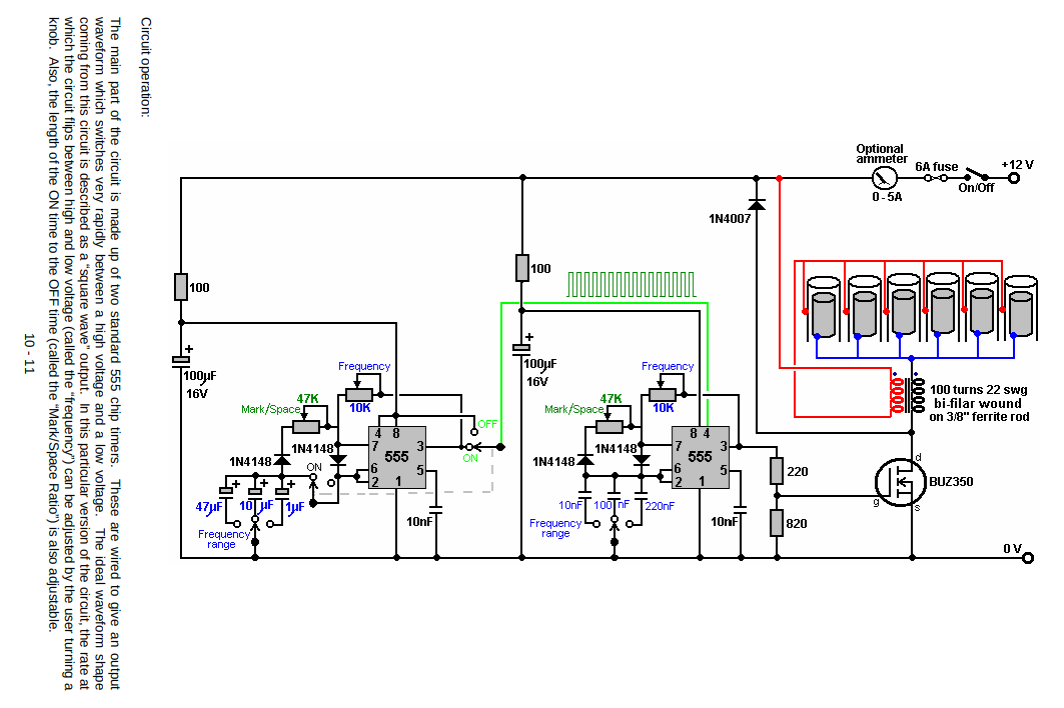
The Dave Lawton 9XA is a versatile pulse and gate generator with variable duty cycle on both 555 timers.
One design note that exists here, is that Pin 3 Output of timer 1 is used to provide Vcc power to Pin 4 on Timer 2. This means an inherent latency is always introduced by the 1st RC charge cycle to power up the 2nd timer. This would cause a partial leading pulse. Other than that issue, it's a pretty solid circuit.
Using a BUZ350 mosfet to pull down the B+ 12V through the cell and negative choke.
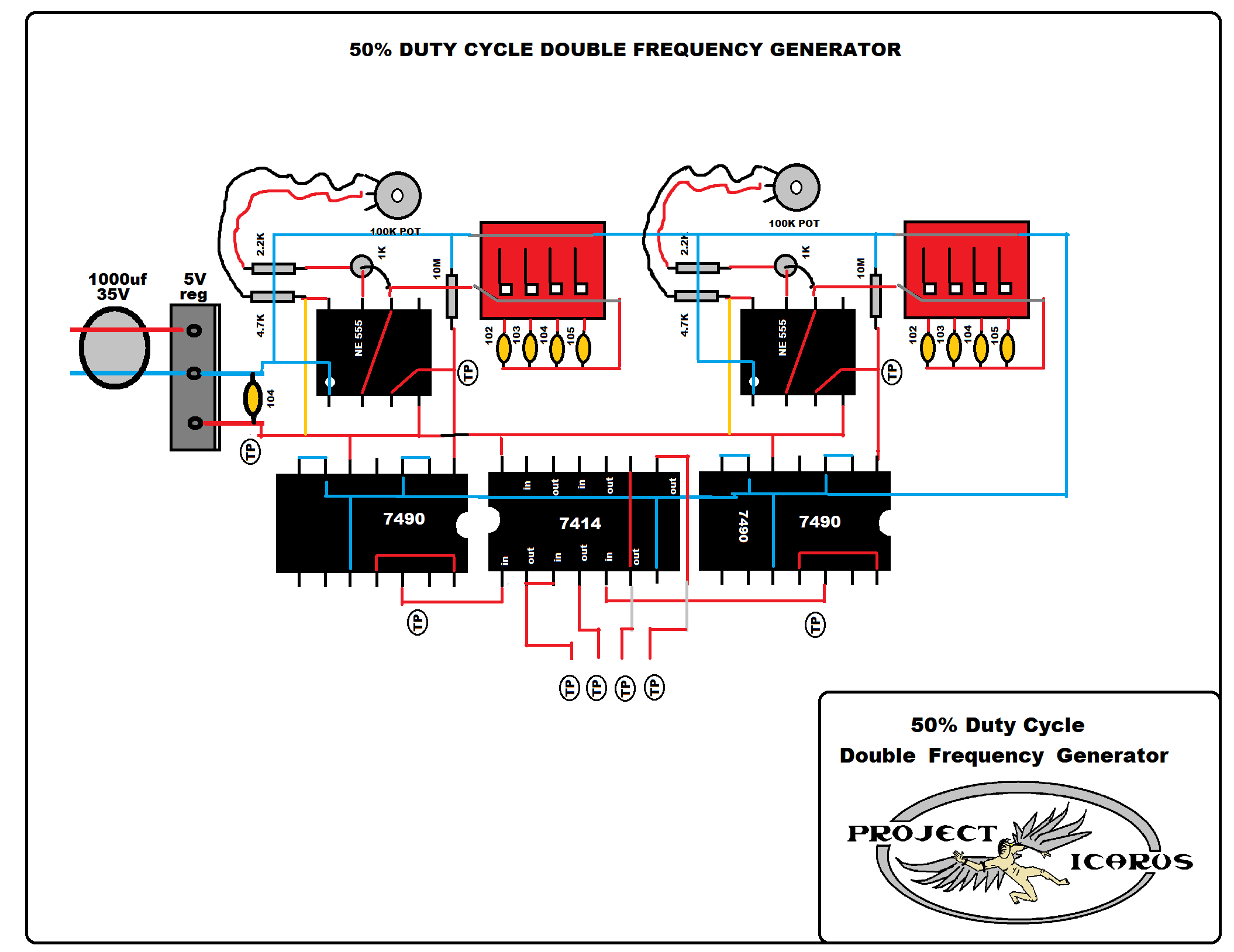
50% Duty Cycle Double Frequency Generator
PDF Download: http://irondmax.com/pdf/ProjectIcarus.pdf
|
50% Duty Cycle Generator |
 |
|
50% Duty Cycle Divide X 10 |
 |
|
Gated Frequency |
 |
|
Signal Inverter |
 |
|
5 Volt Regulator |
 |
|
Clock Pulse Generator |
 |
Adjustable Duty Cycle Gated Pulse Frequency
One can use a 555 with two 1N4148 diodes to allow independent control of duty cycle ON/OFF times. Each diode has a 100k 10-turn precision potentiometer placed in series to capacitor as shown below. Rotary switch for selection of different capacitor values can allow frequency range selectivity. "RA" below can be a potentiometer to allow for frequency adjustment.
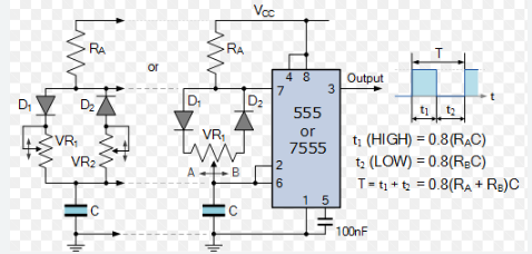
Photo from Electronic Tutorials: Electronic Tutorials (555)
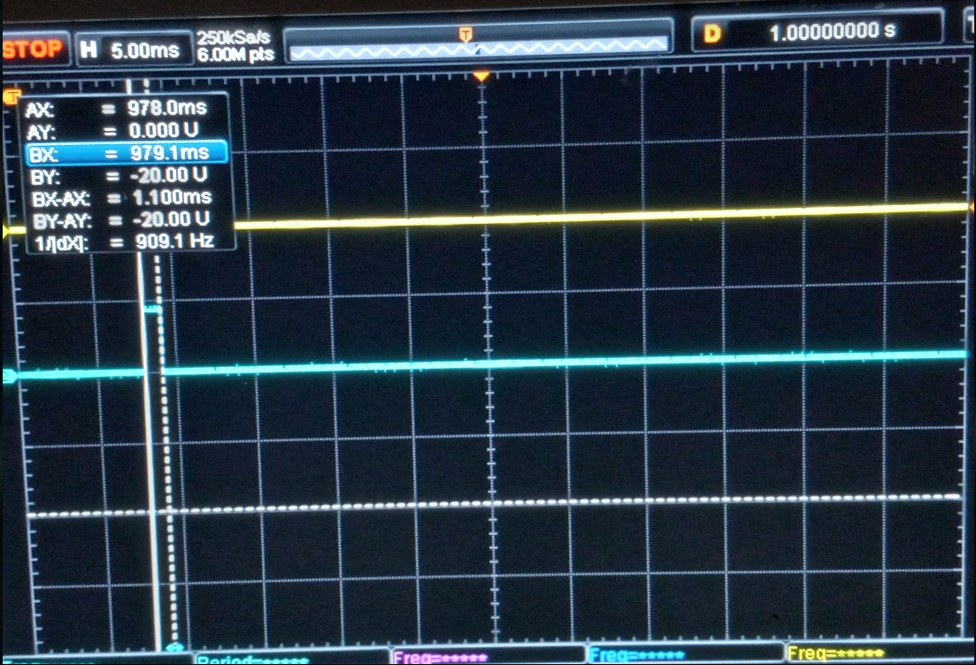
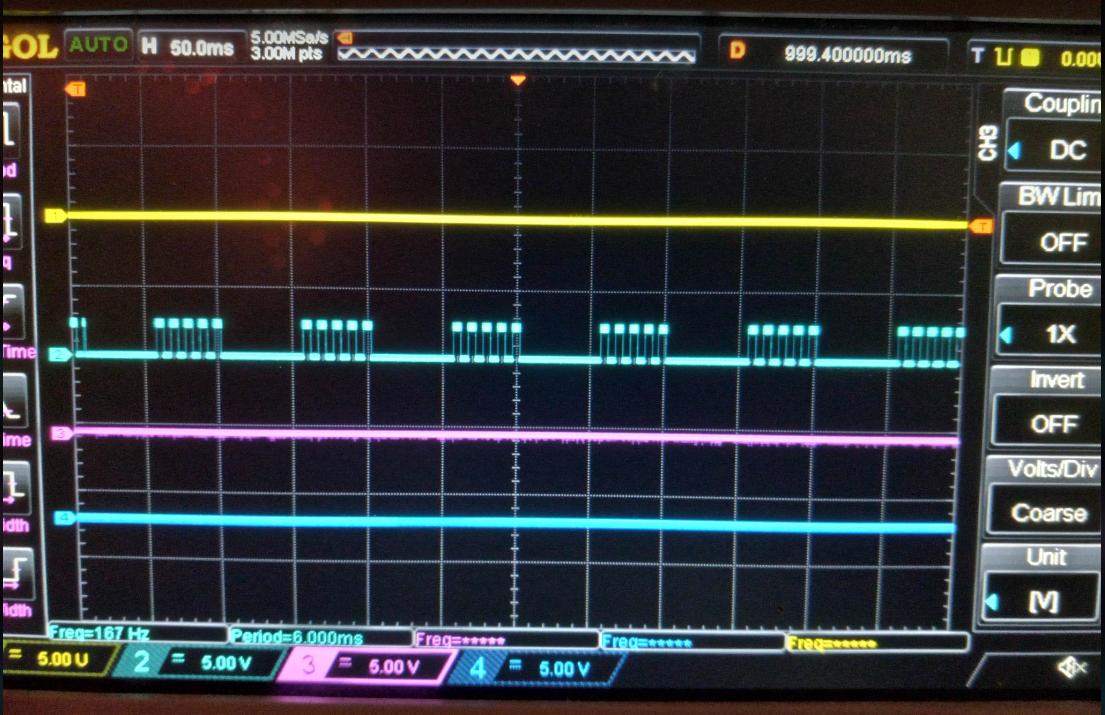
In the build below, pin 3 of 555 was also output to CD4017 decade counter stage to produce a gate. This provided clock synchronization, and only allows 5 pulses per gate ON time. Otherwise, any independent driver of CD4017 would produce clock drift and not allow a discrete number of pulse per gate ON time. Beauty of shift registers in 4017's is even though a 1mS ON time may be occurring, the whole period will be used to divide by 10. Thus maintaining a 50% gated pulse time if desired. Both the adjusted pulse train from Pin #3 and output of CD4017 (Pin #12) is put into inputs (Pin #1 and Pin #2) of a 7408 AND logic gate chip. Pin #3 on 7408 is output, which is shown in yellow below on scope. Circuit driver side isolation may be achieved with H11D1 similar to the 9XA.
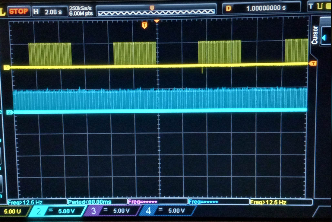
Gate can be adjusted by RA resistor to produce increase occurrences of pulse train
Pulse duty cycle ON time, down to lowest, measured at 1mS.
Adjustable Gated Pulse Freq Gen
This method allows pulse duty cycle control, and synchronized gate to pulse train.
9XA Method
The 9XA was a circuit that Stan used to produce a gated pulse frequency via two H11D1 optocouplers. The optocouplers were driven by two independent stages of 555 timer clock frequency into 3 7490 decade counter ICs. The 7490s provided divisions of 555 frequency, but also produced 50% duty cycle pulses. Below, "A" is one 555/7490 stage and "B" is second 555/7490 stage. The two optocouplers produce an equivalent to AND logic gate.
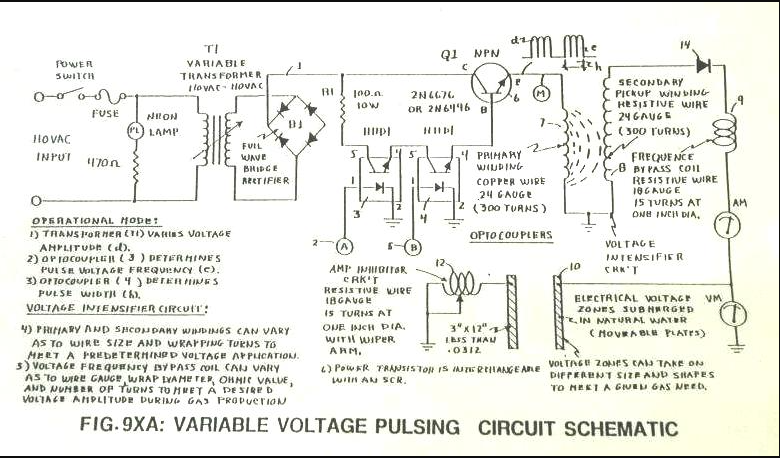
Figure 1: 9XA schematic
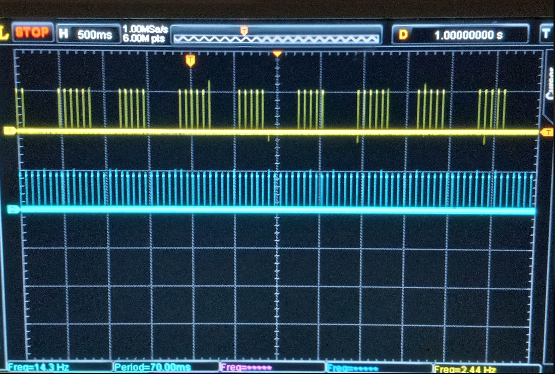
Below is an 9xa scope shot, showing how two independent 9XB style frequency generator's outputs were used to trigger two H11D1 optocouplers to produce a gated pulse train as shown in schematic. In this setup, I had 555's produce a 100khz output to 4 CD4017 dividers. This allowed a 10khz with 50/50 duty cycle to be achieved. LED is just for visual confirmation. If looking closely, you can see how the gating generator isn't synchronized with frequency generator. This causes extra pulses to arise during gated ON times, also called "clock drift".
NOTE: CD4017s were used in place of 7490s, they accomplish the same task with less wiring required.
Video Link: 9XA Circuit Waveform
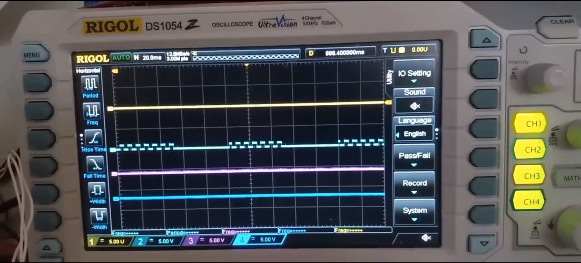
2nd setup had a modification where both signals from 555/CD4017 were fed into an 7408 AND logic gate. This produced the waveform seen below. In this instance, only 1 H11D1 optocoupler was required.
LED providing visual verification of pulse waveform.
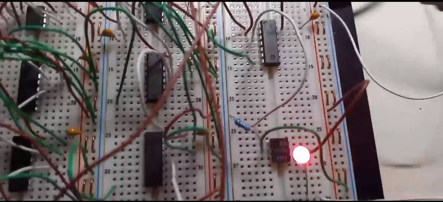
Video Link: 9XA, 7408 mod
9XA does provide a 50% duty cycle pulse frequency with a 50% duty cycle gate frequency. However, clock drifting is an issue if both waveform generators are used independently. If both decade counter stages are driven from same 555, a synchronized clock can be achieved. It is unclear if Stan synchronized with one 555.
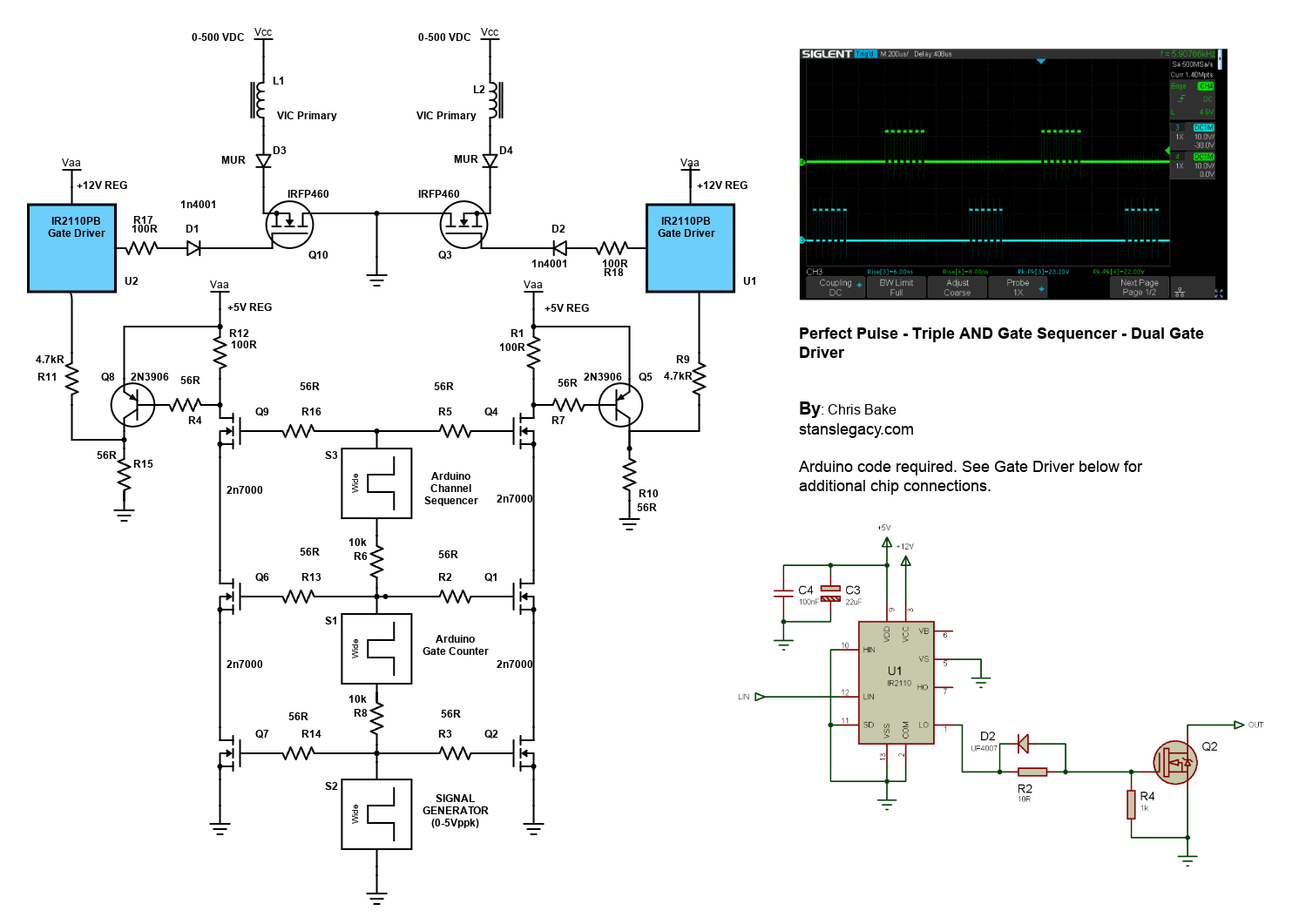
2 Arduino - Dual Channel - Triple AND Gate (Perfect Pulse Driver)
By: Chris Bake
Arduino Code: https://bitbucket.org/cbake6807/dualtripleseq/src/master/
Parts List
- External Signal Generator: 0-5Vppk output.
- Power Supply: ATX is ideal, providing +5V REG and +12V REG.
- 2N7000 Signal MOSFETs: Quantity 6.
- IRFP460 or Similar Power N-channel MOSFET: Quantity 2.
- 56Ω 1/8W Resistors: Quantity 10.
- 100Ω 1/2W Resistors: Quantity 2.
- 4.7kΩ Resistors: Quantity 2.
- 2N3906 PNP General Purpose Transistor: Quantity 2 (can be substituted with any general PNP transistor).
- IR2110PB Gate Driver Chip 14-pin: Quantity 2.
- Arduino Nano (or similar): Quantity 2 (must support hardware PCNT).
- Rotary Encoder: Quantity 1.
Software Requirements
- Arduino IDE: Ensure it is installed and updated to the latest version.
- Encoder Library: Install via the Arduino Library Manager.
Arduino Setup
Pulse Counter Arduino
-
Upload Script
- Open the Arduino IDE.
- Connect the first Arduino (PulseCounter) to your PC.
- Open
PulseCounter.inofrom the provided file. - Upload the script to the Arduino.
-
Connect the Encoder
- Connect the encoder's VCC to the Arduino's 5V pin.
- Connect the encoder's GND to the Arduino's GND pin.
- Connect the encoder's CLK and DT pins to two digital pins on the Arduino D2 and D3.
- Connect the encoder's Button pin to D5.
-
Verify Encoder Output
- Open the Serial Monitor in the Arduino IDE.
- Rotate the encoder and check the output to confirm it is functioning correctly.
Adding a Pushbutton for Sync Mode Toggle
Parts Required
Hardware Connections
-
Connect the Pushbutton
- Connect one terminal of the pushbutton to the Arduino's 5V pin.
- Connect the other terminal of the pushbutton to digital pin 4 on the Arduino.
-
Add a Pull-Down Resistor
- Connect a 10kΩ resistor between digital pin 4 and GND. This ensures that the pin reads LOW when the button is not pressed.
Summary of Connections
Sequencer Arduino
- Upload Script
- Disconnect the PulseCounter Arduino and connect the second Arduino (Sequencer) to your PC.
- Open
Sequencer.inofrom the provided file. - Upload the script to the Arduino.
Pin Mapping and Connections
Connecting the Two Arduinos
-
PulseCounter Arduino to Sequencer Arduino
- PulseCounter D5 (Input) ← Signal Generator
- PulseCounter D9 (Output) → Sequencer D2 (Input)
-
Sequencer Arduino Outputs
- Sequencer D9 (Output) → Input to the first AND gate tree
- Sequencer D10 (Output) → Input to the second AND gate tree
Note: The schematic shows the outputs merged due to limitations, but there should be dual outputs from the sequencer, each connecting to a separate AND gate tree.
Gate Driver Chip Connections
IR2110PB Gate Driver Chip
-
Power Connections
- VCC (Pin 3) → +12V REG
- VSS (Pin 12) → GND
-
Input Connections
- LIN (Pin 11) → Arduino PWM pin (as per script)
- HIN (Pin 10) → Arduino PWM pin (as per script)
-
Output Connections
- LO (Pin 1) → Gate of the IRFP460 MOSFET
- HO (Pin 7) → Gate of the second IRFP460 MOSFET
- VS (Pin 6) → Source of the high-side MOSFET
-
Bootstrap Capacitor
- Connect a 0.1µF capacitor between VB (Pin 8) and VS (Pin 6).
-
Other Components
- D2: Place a 1N4001 diode between VB (anode) and VCC (cathode).
- R2: Connect a 10Ω resistor between LO and the gate of the MOSFET.
Schematic Overview
Refer to the schematic image to visualize these connections. The IR2110PB gate driver chips control the IRFP460 MOSFETs, enabling high-power switching of the VIC (Voltage Intensifier Circuit) primaries.
Additional Notes
- Resistor Tolerances: The resistors can have a large tolerance. The 56Ω value is selected to preserve signal clarity. Any value ≤220Ω should be acceptable.
- Merged Outputs: The Arduino Channel Sequencer has 2 outputs shown merged due to Scheme-It limitations.
Off The Shelf - Waveform Generators
Economical Off-the-Shelf Signal Generators with Dual Channels
Signal generators are essential tools for developing, testing, and troubleshooting electronic circuits. For projects inspired by Stanley Meyer's technology, having a versatile and affordable dual-channel signal generator can be particularly useful for driving components, testing resonance, and creating pulse patterns. In this article, we will explore several economical, off-the-shelf signal generators that offer dual-channel functionality, describing their features and potential applications.
1. JDS6600 Signal Generator
The JDS6600 is an economical dual-channel function generator that offers a wide range of waveforms, including sine, square, triangle, pulse, and arbitrary waveforms. This generator is capable of producing signals up to 60 MHz (depending on the model), with adjustable amplitude, frequency, and duty cycle.
-
Dual-Channel Output: The JDS6600 provides two independent channels, allowing you to generate two different waveforms simultaneously. You can adjust parameters such as frequency, phase shift, and amplitude independently for each channel, which is ideal for testing circuits that require two synchronized or complementary signals.
-
LCD Display: The device features a clear LCD screen, making it easy to adjust and monitor waveform settings.
-
Application: This signal generator is suitable for hobbyists and professionals needing an affordable way to experiment with dual-channel signals for applications such as driving transformers, triggering oscillators, or testing resonance conditions.
2. FeelTech FY6900 Function Generator
The FeelTech FY6900 is another affordable, dual-channel signal generator, offering a maximum frequency of up to 60 MHz. This device is popular among hobbyists and DIY electronics enthusiasts due to its versatility and ease of use.
-
Waveform Variety: It can generate a wide range of waveforms, including sine, square, triangle, ramp, pulse, and arbitrary signals, making it versatile for different testing scenarios.
-
Dual Output: The FY6900 features two fully independent output channels, allowing users to generate different waveforms with independent frequency, amplitude, and duty cycle settings. The dual-channel functionality makes it useful for creating complementary signals or testing differential circuits.
-
Modulation Options: This signal generator supports amplitude modulation (AM), frequency modulation (FM), and pulse-width modulation (PWM), which adds significant value to the tool, making it ideal for more advanced applications, such as resonance testing or creating complex waveforms for energy research.
3. Koolertron DDS Function Generator
The Koolertron DDS Function Generator is an affordable digital signal generator that offers dual-channel functionality with a maximum frequency of up to 60 MHz. It is a popular option for those who need a reliable generator without spending too much.
-
Dual-Channel Output: The Koolertron signal generator allows for two independent outputs, each with configurable amplitude, frequency, and waveform type. It supports sine, square, triangle, and custom arbitrary waveforms.
-
USB Connectivity: The Koolertron signal generator includes USB connectivity, allowing users to connect to a computer for remote control, data logging, and saving waveform parameters. This is a useful feature for those looking to conduct more systematic experiments.
-
Application: With dual-channel capabilities, this generator is well-suited for experiments that require precise signal synchronization or testing components in different configurations.
4. SainSmart DDS140 Dual-Channel Signal Generator
The SainSmart DDS140 is another economical solution for those looking for a dual-channel signal generator. This function generator is well known for its versatility and intuitive interface.
-
Dual Channels: Both channels are fully adjustable, allowing for different waveform types, frequencies, and amplitudes. The output frequency is adjustable up to 40 MHz, which is sufficient for most hobbyist-level testing and circuit development.
-
Modulation Capabilities: The SainSmart DDS140 features frequency and amplitude modulation, which is useful for generating complex waveforms for more detailed circuit analysis.
-
User-Friendly Interface: With an easy-to-read display and straightforward controls, the SainSmart DDS140 is ideal for beginners who want a simple yet effective tool for signal generation.
5. Hantek 6022BE PC-Based Oscilloscope with Function Generator
The Hantek 6022BE is an economical PC-based oscilloscope that also features a dual-channel function generator. This device is particularly interesting because it combines the capabilities of a signal generator and an oscilloscope into one affordable package.
-
PC Integration: The Hantek 6022BE uses a USB connection to interface with your computer, allowing you to generate signals and analyze them using the same software. It can generate waveforms such as sine, square, and triangle, with adjustable amplitude and frequency.
-
Two-Channel Generator: The built-in function generator allows for two channels of signal output, with adjustable frequency and amplitude. This feature is beneficial for projects that require simultaneous signal analysis.
-
Application: This tool is ideal for those who want to combine waveform generation and signal analysis in a single, cost-effective package.
Conclusion
Economical off-the-shelf signal generators with dual-channel functionality are valuable tools for developing and testing electronic circuits. The JDS6600, FeelTech FY6900, Koolertron DDS, SainSmart DDS140, and Hantek 6022BE each offer versatile solutions with distinct features that make them suitable for different applications.
Whether you are driving transformers, testing resonance conditions, or creating complementary signals for energy research, these affordable dual-channel signal generators provide the flexibility and functionality needed to meet your experimental requirements. By selecting the right tool for your needs, you can make your research more efficient and achieve better results without breaking the bank.