To develop and utilize a **hydrogen gas reclaim system** capable of performing water purification on demand without using chemical filters.
##### **Assembly Stage:** **Catalytic Dome Assembly** (10/30) positioned on top of and in space relationship to a Quenching Nozzle (20) affixed on top of and to a natural Water Fuel Cell, as illustrated in Figure 24 as to Figures 24SA, Figure 24SB, and 24SC.| Figure 24SA | Figure 24SB | Figure 24SC |
| [](https://stanslegacy.com/uploads/images/gallery/2024-10/H40XNTZkh9JH6UrX-image-1729264485208.png) | [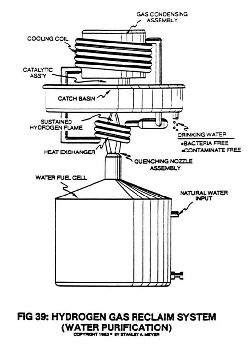](https://stanslegacy.com/uploads/images/gallery/2024-10/S1khIgN4tHvwcpGa-image-1729264594060.png) |
The gas mixing ratio of said Fuel Cell automatically adjusts the burn rate of **hydrogen gas from 325 cm/sec** to **42 cm/sec**, co-equating the burn-rate of natural gas, as illustrated in Figure 24 as to Figure Graph 23.
| [](https://stanslegacy.com/uploads/images/gallery/2024-10/H40XNTZkh9JH6UrX-image-1729264485208.png) | [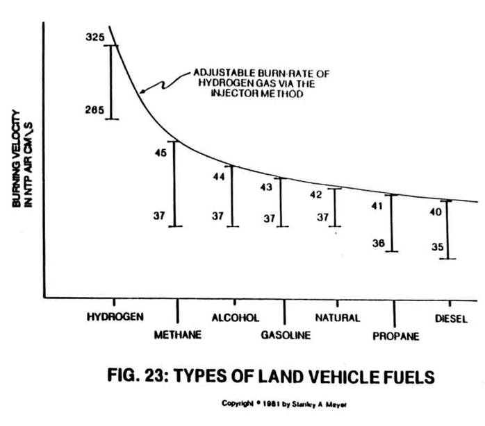](https://stanslegacy.com/uploads/images/gallery/2024-10/agagu4TMrcGFyxIi-image-1729264710483.png) |
The gas flow regulator or **gas valve** (11) can adjust or lower the hydrogen flame temperature below that of burning paper.
This gas modulation process is further used to transport hydrogen gas through conventional gas lines, as shown in Figure 31. [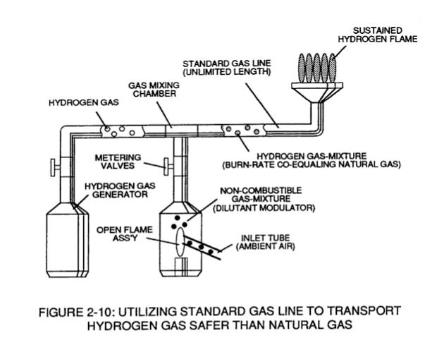](https://stanslegacy.com/uploads/images/gallery/2024-10/2kGCtgvRjd3csfp9-image-1729265366375.png) In another application, the gas modulation technique is also used to run a conventional car engine, as illustrated in Figure 22 as to Figure Graph 23.| [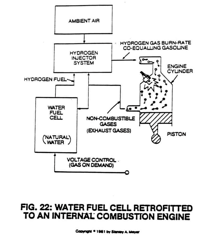](https://stanslegacy.com/uploads/images/gallery/2024-10/Jsrk3KDyzBXETtQy-image-1729264836651.png) | [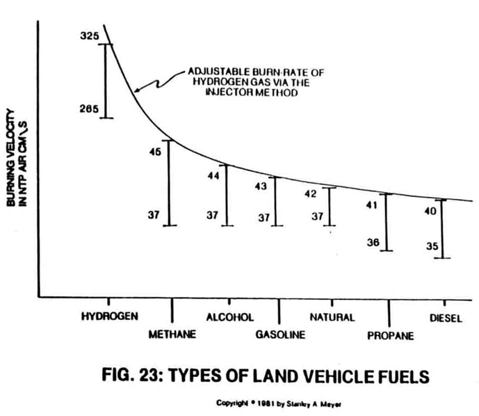](https://stanslegacy.com/uploads/images/gallery/2024-10/dRqIWpgiLbx6o7cZ-image-1729264843227.png) |
| Figure 24SB | Figure 24SC | Figure 24SA |
**Multiple Quenching Circuits** (5a xxx 5n) of Figure 24SB are used to prevent flame-out when the Fuel Cell gases exceed a certain gas velocity.
#### QUENCHING CIRCUIT RELIABILITY: A non-oxidizing material such as alumina (*a type of ceramic material*) is used to form said **quenching disc** (7) to prevent **gas port** (5) enlargement due to chemical interaction and/or heat exposure or both.The **nozzle assembly** (20) itself acts as a heat sink.
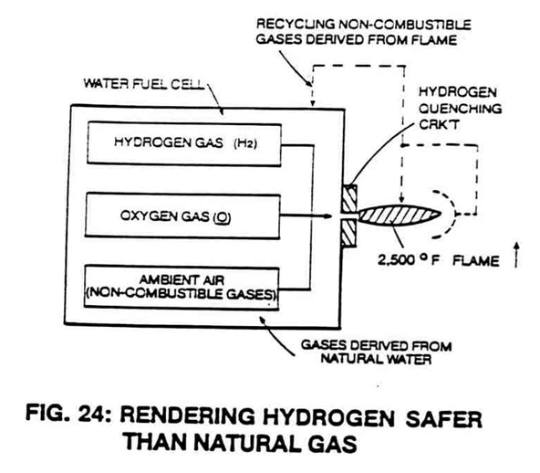
#### SUSTAINING AND MAINTAINING A HYDROGEN GAS FLAME: [](https://stanslegacy.com/uploads/images/gallery/2024-10/H40XNTZkh9JH6UrX-image-1729264485208.png)By simply igniting the Fuel Cell **gases** (6) expelling from said **Quenching Nozzle** (20) of Figure 24SB as to Figure 24, a **hydrogen/oxygen flame** (9) of Figure 24SB as to Figure 24 is sustained and maintained regardless of the gas-rate of said Fuel Cell. Flame projection is achievable beyond six inches while flame temperature is variable up to and beyond **5,000 degrees F**.The **modulated gas mixture** (6) near each **quenching circuit** (5) prior to **gas ignition** (9) helps keep **quenching disc** (7) cool to the touch.
#### #### HYDROGEN LEAKAGE:To help prevent hydrogen gas leakage due to quenching circuit flame-out (*Murphy's law of probability*), said quenching circuits (5a xxx 5n) are prearranged in such a way as to allow an **adjacent flame** (9) to re-ignite the expelling fuel gas.
The **overlapping flame pattern** (12a xxx 12n) of Figure 24SB as to Figure 24SA also aids the hydrogen burning process by concentrating flame temperature in a centralized area while said anti-spark back technique (*quenching circuit*) remains intact. #### SECONDARY BURNING ZONE: To ensure total and complete gas combustion during Fuel Cell operations, a **Catalytic Dome** (10) is placed on top of and in space relationship to said **quenching nozzle** (20), as so illustrated in Figure 24SA. The **hemispherical-shaped dome** (13) performs several functions simultaneously: - captures and entraps any and all combustible gases that somehow escape the gas-burning process; - ignites said combustible gases inside said catalytic dome composed of heat-retaining material (like ceramic); - redirects the burning gases back into the sustained hydrogen flame for continuing burning… superheating the gases for **utilization** (14). In actuality, the **hemispherical dome** (10) of Figure 24SA performs as a secondary combustion zone.| [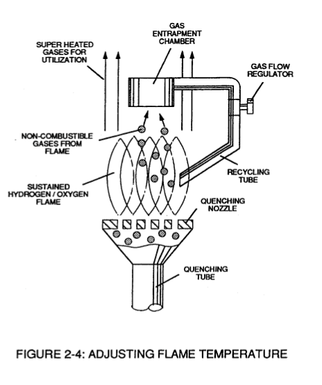](https://stanslegacy.com/uploads/images/gallery/2024-10/8hpCSBSfX4T9ibph-image-1729265496426.png) | [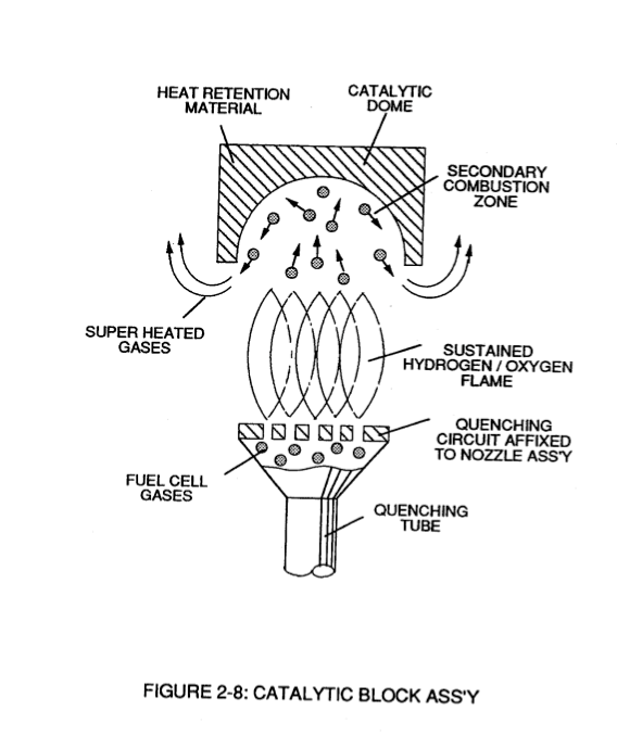](https://stanslegacy.com/uploads/images/gallery/2024-10/yZ24jT2GCuXXp9XD-image-1729265550102.png) |
The superheated gases prevent **Nitrous Oxide** (N2O) formation.
#### WATER PURIFICATION: [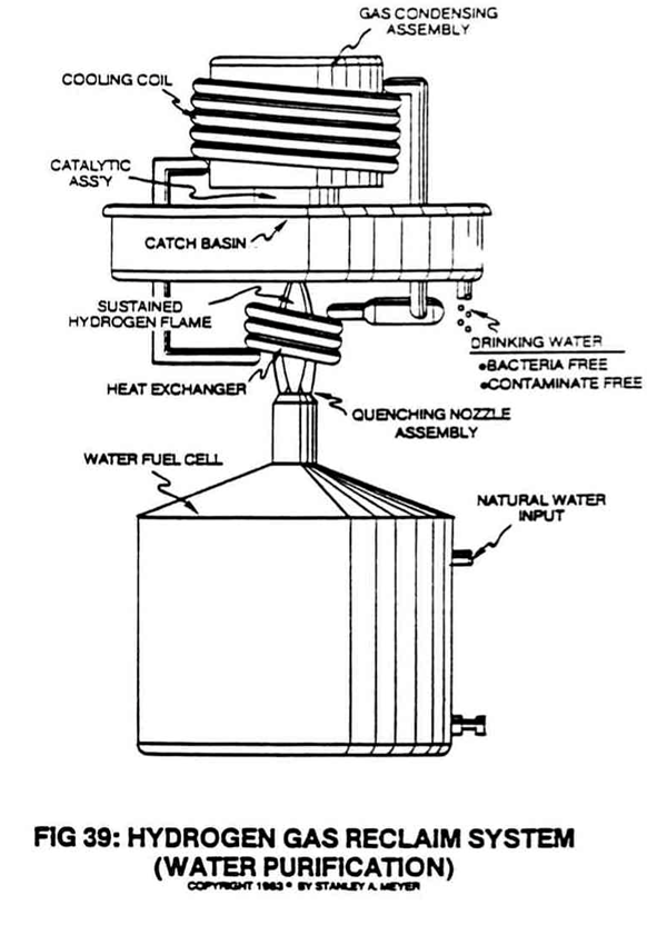](https://stanslegacy.com/uploads/images/gallery/2024-10/yX28FnGLpGx2uNRG-image-1729265037333.png) Water purification is now performed in a three-step operation: contaminates in water remain in the Fuel Cell since voltage is used to dissociate the water molecule; the sustained and maintained hydrogen gas flame kills any and all bacteria that attach themselves to the Fuel Cell gases; cooling the superheated gases moving away from the hydrogen gas flame forms water droplets free of contaminates and bacteria. To accomplish the gas cooling process, a **gas condensing assembly** (40) is attached to the **catalytic block assembly** (10/20), as illustrated in Figure 39. The first stage **heat exchanger** (15) exposed to said **flame temperature** (9) heats a cycling gas that enters into and passes through a **gas expansion chamber** (16). The expanded gas cools another **heat exchanger** (17) exposed to **superheated gases** (14) of Figure 24SA.The resultant temperature gradient performs the water condensing process.
[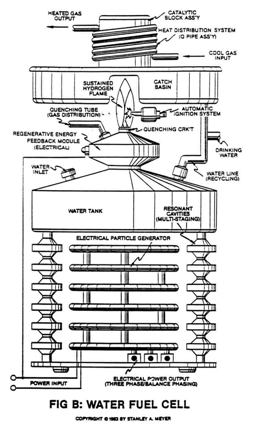](https://stanslegacy.com/uploads/images/gallery/2024-10/tw5sDqY0KoKReDJC-image-1729267754605.png) The **gas condensing assembly** (40) has no moving parts and is self-regulating as to the flame temperature. The collected and stored water inside **catch basin** (18) can be “drained off” for drinking water or re-routed back to the Fuel Cell for hydrogen reuse, as so illustrated in Figure 39 as to Figure B titled “Water Fuel Cell.” During water recycling, the water molecule is re-exposed to **laser energy** (Figure 20FB as to Figure 20K) for **Energy Charging**... duplicating sun exposure.