To design said **rotary electrical generator**, the following design parameters must be utilized to reach maximum operational performance:
**POWER FACTOR OF DESIGN**: 1. Strength of Magnetic Field (number of magnetic flux lines) 2. Velocity or speed at which a magnetic field passes through a conductive wire 3. Number of loops or turns per wire-coil 4. Number of pickup coils 5. Energy input to produce and maintain said rotating electromagnetic field (applied electrical energy) 6. Energy input to rotate or move said electromagnetic field (applied mechanical energy) **Point-of-Observation**: A magnetic flux line does not show signs of deterioration when passing through an electrical conductive wire. **Observations-Test**: An electromagnetic field emanating from a permanent magnet rotating inside an electrical wire-coil produces electrical energy. Said permanent magnet requires no energy input to maintain said magnetic field, see [Thomas Edison generators](https://edison.rutgers.edu/life-of-edison/inventions?catid=91&id=530&view=article). **Typical Rotary Electrical Generator**: Car Alternator **Operational Characteristics**: **maximum duty loading** 1. Apply 120 watts (12 volts x 10 amps) of electrical power to armature winding to produce said electromagnetic field. 2. Apply 5,222 watts (7 hp x 746 watts) to "start" and "rotate" said armature to move said electromagnetic field through said pickup coils during maximum duty loading. 3. Three rotor pickup coils (300 turns per coil; 3 coils per stator ring array) produces 720 watts (12 volts x 60 amps) output during said maximum duty loading. ##### **Second Point-of-Observation**: The **opposing magnetic fields** (a xxx an) (*opposite polarity attraction*) between said armature and said stator ring consumes tremendous amounts of mechanical energy during deformation of said **attraction fields** (a), see Figure 25ZA.Said **opposing magnetic fields** (a) resist said armature rotation.
##### **Observation Test**: Once said **electromagnetic circuit** is formed (a), said **opposite polarity attraction** (*north to south magnetic pole interaction*) tries to prevent armature rotation. *A **stationary armature** (electrically* energized) cannot rotate without exerting mechanical torque (*rotational force*) energy to said armature. Said mechanical energy input is directly proportional to said **magnetic field strength** (a). Increasing said **electromagnetic field strength** (a) requires an increase in mechanical energy input.Counter EMF electrical field is not formed around said pickup coils since said armature is stationary during static testing.
**Scientific Fact**: > Said Maxwell/Faraday Laws of inductance require that a magnetic field must pass through said pickup coil to generate a counter EMF electromagnetic field, see Exhibit AZ, McGraw-Hill Encyclopedia of Science and Technology, Vol. 6, page 144. **Point of Discovery**: Elimination of said "Air Gap" attraction problem can help reduce energy input requirements to produce electricity. --- ##### **The Birth of New Technology: Electrical Particle Generator (EPG)** **Design Objective**: To move and attenuate a permanent magnetic field through a pickup coil array without said "Air Gap." --- #### **Electrical Particle Generator: Assembly & Operability** ##### **A) Magnetic Pathway: Closed loop system** Take a **non-magnetic tube** (*material that will not become permanently magnetized when exposed to a magnetic field and having the capability of distorting said magnetic field through said tubular material without signal distortion… such as aluminum, brass, glass, and/or plastics*) and form a **closed loop pathway** (*without open ends*), as illustrated in (1) of Figure 26 through Figure 30.| [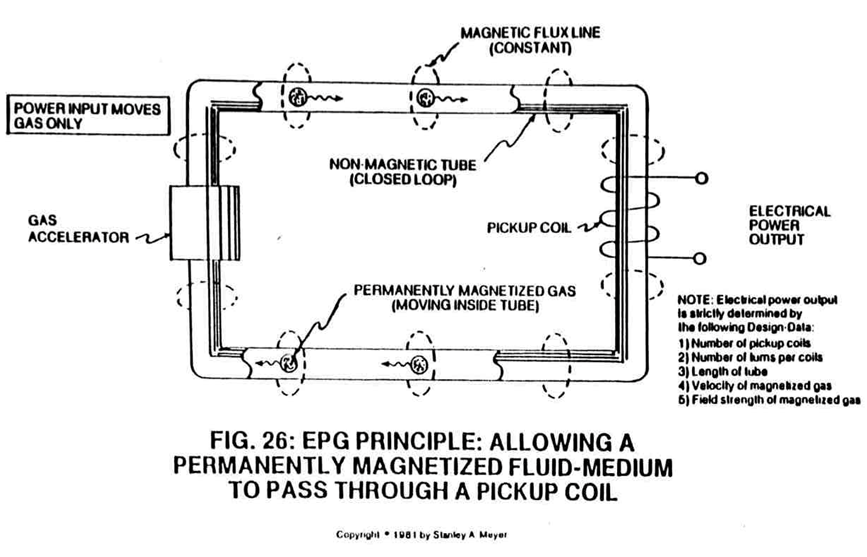](https://stanslegacy.com/uploads/images/gallery/2024-10/tYSeCbe9BF34ik0X-image-1729698664899.png) | [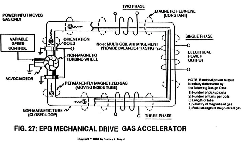](https://stanslegacy.com/uploads/images/gallery/2024-10/vPmH1J09GzeI7YH3-image-1729568840461.png) |
| [](https://stanslegacy.com/uploads/images/gallery/2024-10/jV5842wLneom6bjK-image-1729568848276.png) | [](https://stanslegacy.com/uploads/images/gallery/2024-10/MfYuwau4z4tLpfGE-image-1729568854073.png) |
Wrap a **wire-coil** (2) and/or **coil-array** (2a xxx 2n) around one end of said **non-magnetic tube** (1) to comply with Maxwell/Faraday Laws of Inductance.
[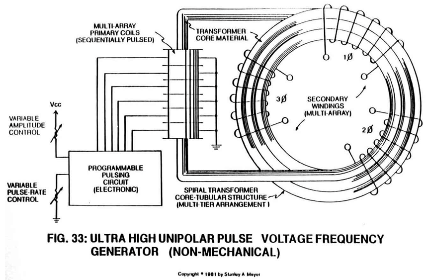](https://stanslegacy.com/uploads/images/gallery/2024-10/iA8DbdlGxg2gL0pE-image-1729624457766.png)Said **pickup coil** (2) is placed around said **spiral pathway** (8) of Figure 33 to form a **coil-array** (2a xxx 2n). ##### **C) Particle Accelerator Assembly: Purpose & Placement** Insert into and affixed a **Particle Accelerator Assembly** (10) to said **closed loop tube** (1) as to (8), locating said Particle Accelerator Assembly on opposite end of **tube** (1) away from said **pickup windings** (2 xxx 2n), as shown in Figure 26. --- [](https://stanslegacy.com/uploads/images/gallery/2024-10/tYSeCbe9BF34ik0X-image-1729698664899.png)Said **Particle Accelerator Assembly** (10) causes and propels a **permanent magnetic fluid-medium** (3 of Figure 26) (*liquid slurry or gases*) to move toward, through, and beyond said **pickup coils** (2) for recycling, as illustrated in Figure 26.Said **Particle** **Accelerator Assembly** (10) can take on different design configurations to utilize different energy inputs to overcome different climatic and operational conditions.
--- A **Mechanical Accelerator Drive Assembly** (20 of Figure 27) utilizes a **non-magnetic turbine wheel** (21) to physically move said **magnetic fluid-medium** (3) inside said **tubular pathway** (1).| [](https://stanslegacy.com/uploads/images/gallery/2024-10/vPmH1J09GzeI7YH3-image-1729568840461.png) | [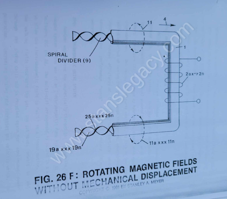](https://stanslegacy.com/uploads/images/gallery/2024-10/0WPinvE1yJJT8VVJ-image-1729699457603.png) |
| [](https://stanslegacy.com/uploads/images/gallery/2024-10/ECD8ihbWga3Tseii-image-1729713795923.png) | [](https://stanslegacy.com/uploads/images/gallery/2024-10/iA8DbdlGxg2gL0pE-image-1729624457766.png) |
Said **mechanical drive system** (20) and/or **Electromagnetic Pump Assembly** (30) can be used separately, joined together, or periodically spaced around said **tubular structure** (1) as to (8).
--- ##### **D) Energy Input: Mechanical to Electrical Interfacing** **Power Train linkage** (22) to said **non-magnetic turbine wheel** (21 of Figure 27 can take different forms:AC/DC Electric Motor powered by solar or conventional electrical power; Hydraulics; Steam Power; Wind Power; Internal combustion engine, and/or manpower.
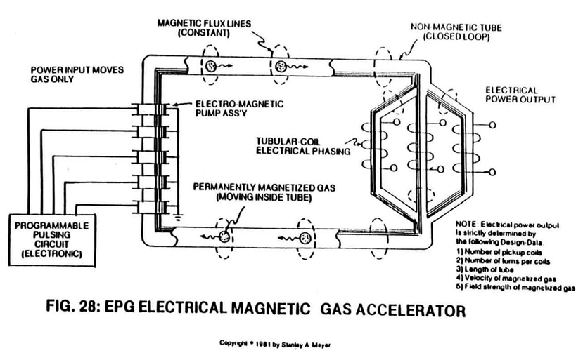
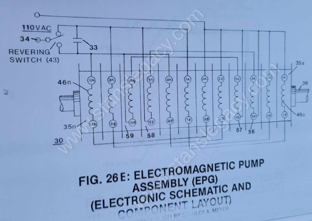
**Electromagnetic Pump Assembly** (30 of Figure 28 as to Figure 33) is energized by a variable AC electrical **power source** (34).| [](https://stanslegacy.com/uploads/images/gallery/2024-10/jV5842wLneom6bjK-image-1729568848276.png) | [](https://stanslegacy.com/uploads/images/gallery/2024-10/iA8DbdlGxg2gL0pE-image-1729624457766.png) |
| [](https://stanslegacy.com/uploads/images/gallery/2024-10/tYSeCbe9BF34ik0X-image-1729698664899.png) | [](https://stanslegacy.com/uploads/images/gallery/2024-10/vPmH1J09GzeI7YH3-image-1729568840461.png) |
| [](https://stanslegacy.com/uploads/images/gallery/2024-10/MfYuwau4z4tLpfGE-image-1729568854073.png) | [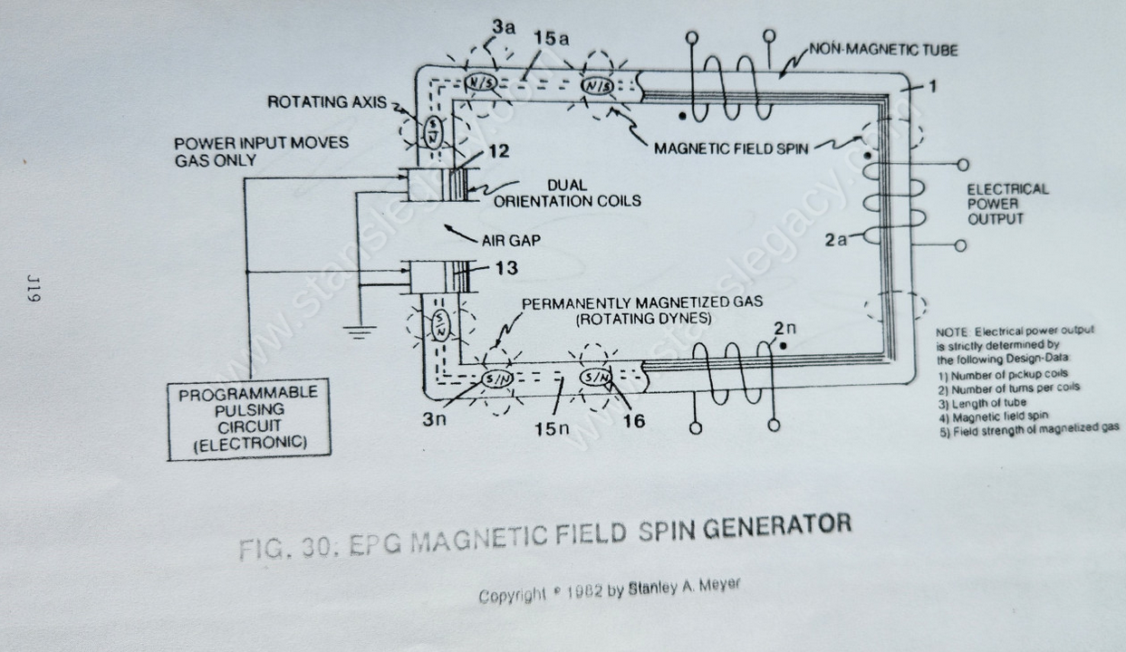](https://stanslegacy.com/uploads/images/gallery/2024-10/HkrFdxXxmCQmMROW-image-1729623833109.png) |
Said **permanently magnetized material** (3) can either be in a liquid slurry and/or gas form.
Said liquid slurry is composed of **micro-size permanently magnetized particles** suspended in a fluid-medium such as **liquid Teflon** or light-oil, forming a homogeneous liquid-mass.
Said permanently magnetized gas is composed of atom-size permanently magnetized particles suspended onto an inert carrier gas such as nitrogen argon, forming a homogeneous gas-mass.
Both homogeneous masses **can be doped** with different permanently magnetized atoms to encourage electromagnetic field enhancement.
**Scientific Fact**: > The smallest part of a permanent magnet is its atomic structure. ##### **F) Magnetic Field Formation: An Electronic Process** Once said **tubular pathway** (1) as to (8) is completely filled with said **permanently magnetized material** (3), said **pickup coil-array** (2a xxx 2n) is electrically energized to produce an electromagnetic field that completely surrounds said **tubular pathway** (8) of Figure 33, exposing said **magnetic material** (3) to said electromagnetic field... causing said **material** (3) to become permanently magnetized...forming a **longitudinal field** (4) of Figure 26 emitting from said **tubular pathway** (1). Said **longitudinal field** (4) remains after said **coil-array** (2a xxx 2n) is de-energized.| [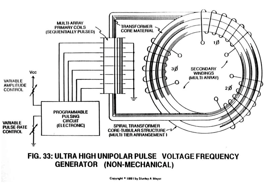](https://stanslegacy.com/uploads/images/gallery/2024-10/jQTQVT4yguejziI3-image-1729568489425.png) | [](https://stanslegacy.com/uploads/images/gallery/2024-10/tYSeCbe9BF34ik0X-image-1729698664899.png) |
No other energy is needed to maintain said **magnetic field** (4).
> **Electronic Fact**: At this point, above said magnetizing process duplicates the same function as a **Toroidal Pulsing Core** in electronic circuit applications. Except said Toroidal core material becomes demagnetized after electrical power is removed. ##### **G) Magnetic Fields Movement: Linear Spin** **Longitudinal movement** (*moving permanently magnetized fluid-medium inside said tubular pathway*) of said **magnetic field** (4 of Figure 26) is simply accomplished when said **Electro/mechanical Pump Assembly** (20) of Figure 27 and/or **Electromagnetic Pump Assembly** (30) of Figure 28 is energized for operability.| [](https://stanslegacy.com/uploads/images/gallery/2024-10/ELdUfU5cNL4H9FcO-image-1729568832482.png) | [](https://stanslegacy.com/uploads/images/gallery/2024-10/vPmH1J09GzeI7YH3-image-1729568840461.png) | [](https://stanslegacy.com/uploads/images/gallery/2024-10/jV5842wLneom6bjK-image-1729568848276.png) |
By attenuating or varying power input to said **power drive systems** (20 and/or 30) likewise varies the recycling speed or velocity of said **magnetic field** (4) moving toward, through, and beyond said **pickup coil-array** (2a xxx 2n)... moving onward to and through said **Power Drive Assembly** (20 and/or 30) once again for continued field recycling.
| [](https://stanslegacy.com/uploads/images/gallery/2024-10/ELdUfU5cNL4H9FcO-image-1729568832482.png) | [](https://stanslegacy.com/uploads/images/gallery/2024-10/0WPinvE1yJJT8VVJ-image-1729699457603.png) |
| [](https://stanslegacy.com/uploads/images/gallery/2024-10/jV5842wLneom6bjK-image-1729568848276.png) | [](https://stanslegacy.com/uploads/images/gallery/2024-10/jQTQVT4yguejziI3-image-1729568489425.png) |
The linear-spin movement of said **magnetic field** (4/11) now duplicates the magnetic field spin of Figure 26ZA without the opposing magnetic field problem (*caused by said "Air Gap"*) associated with standard rotary electrical generators, see **"Pre-History to Development"** again.
Said **Rotary Electrical Generator** (Figure 26ZA) simply moved the armature field in one direction;whereas, the EPG System now moves said **magnetic field** (4/11) in two directions simultaneously:
(4) **linear direction**, (11) **axial** or **spin rotation**. --- ##### **H) Magnetic Field Deflection: Oscillating a permanent magnetic field** To pulsate or vary said **rotational field** (11) moving in a **linear direction** (4), **Dual-Orientational coils** (12/13 of Figure 27) are now inserted into said tubular pathway on opposite side of **Electromechanical Drive System** (20), away from said **pickup coil-array** (2a xxx 2n), as illustrated in Figure (27) as to Figure 30.| [](https://stanslegacy.com/uploads/images/gallery/2024-10/vPmH1J09GzeI7YH3-image-1729568840461.png) | [](https://stanslegacy.com/uploads/images/gallery/2024-10/HkrFdxXxmCQmMROW-image-1729623833109.png) |
The **dual-pulsing coils** (12/13) perform a sequential function:
[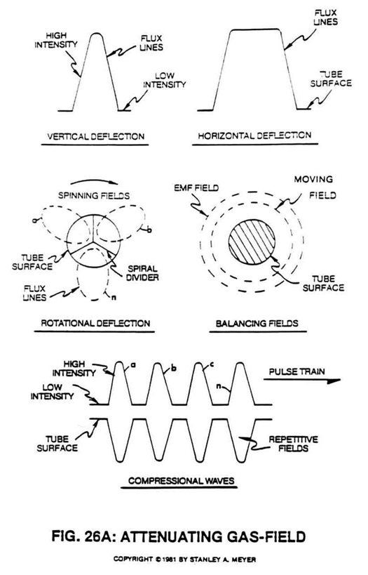](https://stanslegacy.com/uploads/images/gallery/2024-10/EYJwp3N9OUIkVXaP-image-1729730454152.png) First, when electrically energized, said **dual-coils** (12/13) stabilize said **magnetic field** (4/11) since said **turbine wheel** (21 of assembly 20) disrupts the **electromagnetic field alignment** (15a xxx 15n) (*electromagnetic attraction force*) between said **permanently magnetized particles** (3a xxx 3n) moving inside **non-magnetic tubular pathway** (1 as to 8), see Figure 27 as to Figure 30. Secondly, said **moving field** (4/11) is terminated when said **dual-coil assembly** (12/13) is de-energized... allowing said particles (15a xxx 15n) to go into a state of reformation of said magnetic field sequence. Re-energizing said **coils** (12/13) causes said **particles** (3a xxx 3n) to go into alignment once again... reforming **magnetic field** (4/11). Pulsing said **Orientation-coils** (12/13) quickly causes a **vertical deflection** (17a xxx 17n of Figure 26A) of said **magnetic field** (4/11). Pulsing said Orientation-coils slowly causes a **horizontal deflection** (18a xxx 18n of Figure 26A) of said **magnetic field** (4/11).In both cases, said **reforming** **magnetic wave-forms** (17a xxx 17n and/or 18a xxx 18n) are oscillating inside said **coil-array** (2a xxx 2n)... producing electrical energy.
---**Pulse-frequency electrical output** (23 of Figure 30 as to Figure 27) is strictly determined by the pulse-rate of said **orientation coils** (12/13).
| [](https://stanslegacy.com/uploads/images/gallery/2024-10/HkrFdxXxmCQmMROW-image-1729623833109.png) | [](https://stanslegacy.com/uploads/images/gallery/2024-10/vPmH1J09GzeI7YH3-image-1729568840461.png) |
| [](https://stanslegacy.com/uploads/images/gallery/2024-10/iA8DbdlGxg2gL0pE-image-1729624457766.png) | [](https://stanslegacy.com/uploads/images/gallery/2024-10/yHKotVDKYIEID5GY-image-1729131224050.png) |
**Transformer interaction** (*magnetic field coupling*) between said **Orientation Coils** (12/13) and said **pickup coils** (2a xxx 2n) can "NOT" occur since said **particles** (3a xxx 3n) are permanently magnetized.
The magnetic pulsing process simply spins the dyne-axis of **said particles** (3a xxx 3n) to oscillate and attenuate a **permanent** **magnetic field** (4/11 as to 17/18), as illustrated in Figure 30 as to Figure 26 through Figure 33.| [](https://stanslegacy.com/uploads/images/gallery/2024-10/HkrFdxXxmCQmMROW-image-1729623833109.png) | [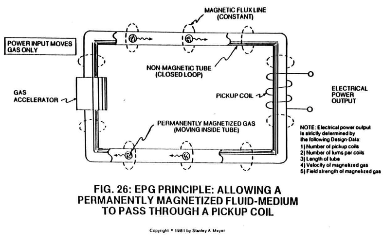](https://stanslegacy.com/uploads/images/gallery/2024-10/YITRFOekWD3T86QW-image-1729713849522.png) |
The **multi-channel spiral divider** (19a xxx 19n) is composed of any type of material (*such as electrical steel M27*) that will "NOT" become permanently magnetized (*when exposed to said moving **magnetic field** (4)*) when "shunting" said **magnetic field** (11a xxx 11n), as shown in Figure 26A sub-titled "Rotational Deflection."
| [](https://stanslegacy.com/uploads/images/gallery/2024-10/oU5VWJKo3ggJE0h3-image-1729730448270.png) | [](https://stanslegacy.com/uploads/images/gallery/2024-10/0WPinvE1yJJT8VVJ-image-1729699457603.png) |
If more **longitudinal magnetic fields** (19a xxx 19n) are required... simply increase the number of **pathway channels** (19).
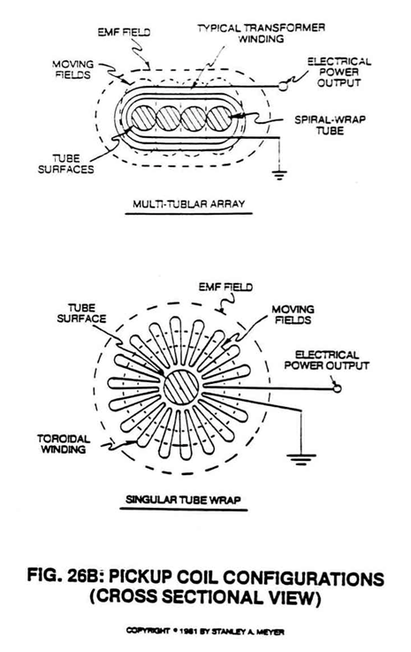
[](https://stanslegacy.com/uploads/images/gallery/2024-10/iA8DbdlGxg2gL0pE-image-1729624457766.png)To increase said **magnetic flux lines** (11a xxx 11n) still further, said **pathway** (1) is now spiraled (8 of Figure 33) (*in spaced relationship to each other*) inside said pickup **coil-array** (2a xxx 2n), as illustrated in Figure 33 as to cross-sectional drawing titled "Multi-tubular array"of Figure 28A.The greater number of spiral-turns (8a xxx 8n) the greater number of right-hand lines transverses said pickup coil array (2a xxx 2n) during pulse-form stage.
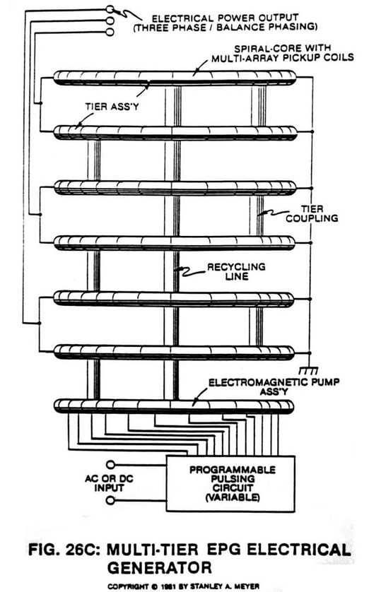
---The number of "shunting" magnetic fields (11a xxx 11n) times (x) the number of spiral pathways (8a xxx 8n) determine the magnetic field strength of said EPG system of Figure 26C.
| [](https://stanslegacy.com/uploads/images/gallery/2024-10/7Z9VbD5lJjjzV6cR-image-1729730668576.png) | [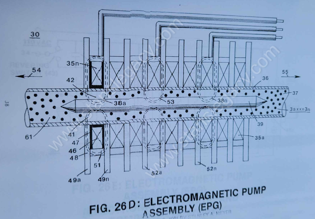](https://stanslegacy.com/uploads/images/gallery/2024-10/USfOHAa5qEsVeEk4-image-1729734343970.png) |
To speed up said **magnetic field spin** (11a xxx 11n), simply increase the velocity of said **magnetized fluid-medium** (3a xxx 3n) traveling through said **pathways** (19a xxx 19n)... or vice versa.
By increasing the **number of turns** (*twist configurations*) (25a xxx 25n of Figure 26F) per linear measurement of said **spiral-divider cluster** (19a xxx 19n) also increases said **magnetic spin** (4/11) still further once said **fluid-velocity** (4) is reached. In both cases, said **magnetic field spin** (11a xxx 11n) is not subject to the rotational/mechanical limitation of said **Rotary Electrical Generator** of Figure 26ZA.| [](https://stanslegacy.com/uploads/images/gallery/2024-10/0WPinvE1yJJT8VVJ-image-1729699457603.png) | [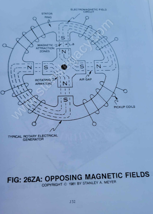](https://stanslegacy.com/uploads/images/gallery/2024-10/Dw9PvTJ5eDTFGI7g-image-1729699080588.png) |
**--- Unidirectional pulsing** (27/28) occurs since the **Linear-Spin movement** (11) of said **pulsating magnetic field** (17/18) is moving in one direction.
**--- Balance-Phasing** (*equal magnetic field strength between said pickup coil-array 2a xxx 2n*) is automatic since **particle velocity** (4) remains constant while passing through said **close-loop tubular pathway** (1).
> Series to parallel hookup of said **coils** (2a xxx 2n) determines amp draw as to applied voltage. Power Output = Amps x Voltage. **[](https://stanslegacy.com/uploads/images/gallery/2024-10/jV5842wLneom6bjK-image-1729568848276.png)Pickup coil-array phasing** (26a xxx 26n) also occurs when splitting said **tubular pathway** (1) into **parallel legs** (1a xxx 1n), as shown in Figure 28. **Electrical Power Output: Power Factor of Design** Electrical power output of said **Electrical Particle Generator** (EPG) is determined as subscribed below: 1. The velocity or movement of said **permanent magnetic fluid-medium** (3a) inside **tubular pathway** (1) (*magnetic field movement per second in a linear direction*). 2. The number of **pathway-channels** (19a xxx 19n) per **spiral-divider** (9) forming **magnetic circuits** (11a xxx 11n) per **spiral-divider** (9) spinning in a linear direction per 360 degrees (*the number of magnetic fields formed per second*). 3. The number of turns or twist per (25a xxx 25n) unit length of said **spiral divider** (9) inserted into said **tubular pathway** (1), the number of magnetic fields spins of said **multi-fields** (11a xxx 11n) per second of linear-travel. 4. The magnetic field strength (*number of magnetic flux-lines per unit volume of said magnetic **fluid-medium** (3)*). 5. The number of **tubular-legs** (8a xxx 8n) spiraled inside said pickup **coil-array** (2a xxx 2n). The number of **multi-rotational fields** (11a xxx 11n) formed per turns of **tubular legs** (8a xxx 8n). 6. The pulse-rate frequency of said **orientational coils** (12/13) to spin or rotate said dyne-axis of said **magnetic fluid-medium** (3) to oscillate said **permanent magnetic field** (11a xxx 11n). 7. The number of turns per coil of wire. 8. The number of coils per **coil-array** (2a xxx 2n). --- ##### **L) Power Input: To Start & Maintain EPG Operations** Power input is required to move said **magnetic fluid-medium** (3) through said **closed-loop tubular pathway** (1). Power input is also required to rotate said dyne-axis of said magnetized **fluid-medium** (3).The basic purpose of said power input is to physically attenuate said **permanently magnetized fluid-medium** (3)... which in turn oscillates a **permanent magnetic field** (4/11).
##### **M) EMF Counter Measures: Minimizing Power Input** To help minimize opposition to the movement of said magnetic fluid-medium during power on-stage, said pickup **coil array** (2a xxx 2n) of Figure 33 as to Figure 26F is placed and aligned end-to-end around said **pathway** (8a xxx 8n) for the purpose of coupling and forming a single and **continuous magnetic field** (31) or any type of electromagnetic field emanating from said **pickup coil-array** (*during duty loading*) is wrapped and positioned around said **pickup coil-array** (2a xxx 2n)... forming a **concentric magnetic ring** (31) around said **pickup coil-array** (12/13) as illustrated in Figure 26A sub-titled "Balancing Fields." Said **oscillating magnetic ring** (31) also forms a **concentric magnetic ring** (29) inside and below said **tubular pathway** (1). The space **formed** (32) between said **magnetic fields** (29 and 31) allows said magnetic lines to cross one another... reducing the opposition to the magnetic field movement.In other words, passing the force-lines between each other magnetic field without said fields opposing each other.
> **Maxwell/Faraday Laws** demonstrate that a space is formed between magnetic flux-lines... this is also known as the standing magnetic wave theory. By synchronizing said **magnetic compression wave** (oscillating magnetic field 17/18) with said **EMF field** (31) termination, EMF field opposition is held to a minimum. See Figure 26A subtitled "Compression Waves." When **EMF field** (31) is formed, said **pulsating magnetic field** (29) forming **concentric ring** (29) is turned off (switched off).| [](https://stanslegacy.com/uploads/images/gallery/2024-10/YITRFOekWD3T86QW-image-1729713849522.png) | [](https://stanslegacy.com/uploads/images/gallery/2024-10/EYJwp3N9OUIkVXaP-image-1729730454152.png) |
| [](https://stanslegacy.com/uploads/images/gallery/2024-10/0WPinvE1yJJT8VVJ-image-1729699457603.png) | [](https://stanslegacy.com/uploads/images/gallery/2024-10/7Z9VbD5lJjjzV6cR-image-1729730668576.png) |
**The Electromechanical actuator** (*Electromagnetic Pump Assembly (30)*) attached to said **tubular pathway** (1) operates as a direct-drive principle of a linear induction motor.
[](https://stanslegacy.com/uploads/images/gallery/2024-10/rYPtRRwOcSG20Hyf-image-1729730524941.png)The **coil-array** (35a xxx 35n) of Figure 26C, besides being the stator, the **magnetic field medium** (3a xxx 3n) is displaced along a movable/non-movable electromagnetic tubular surface (*of Figure 26C) which, in reference to Figure 28*) acts as a bearing surface (since **said surface** (35a xxx 35n) is fixed).| [](https://stanslegacy.com/uploads/images/gallery/2024-10/EYJwp3N9OUIkVXaP-image-1729730454152.png) | [](https://stanslegacy.com/uploads/images/gallery/2024-10/6XHKhvyo7Tgyu86I-image-1729730651882.png) |
| [](https://stanslegacy.com/uploads/images/gallery/2024-10/tYSeCbe9BF34ik0X-image-1729698664899.png) | [](https://stanslegacy.com/uploads/images/gallery/2024-10/iA8DbdlGxg2gL0pE-image-1729624457766.png) |
The **magnetic pump assembly** (30) may operate on three-phase alternating current or with a **capacitor** (33) (*see schematic drawing Figure 26E as to Figure 26C*) on single-phase alternating current.
| [](https://stanslegacy.com/uploads/images/gallery/2024-10/M7inajv1n4YpLydq-image-1729712616828.png) | [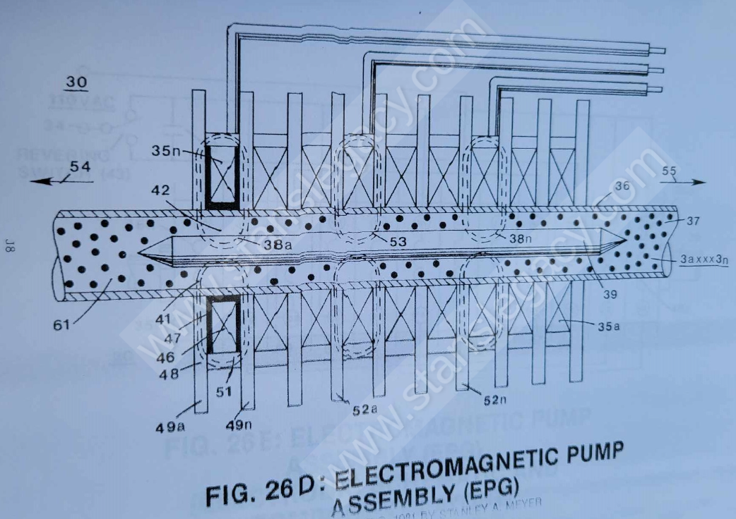](https://stanslegacy.com/uploads/images/gallery/2024-10/aSwUAQH6JJ5mVGW9-image-1729734071459.png) |
A simple **mechanical switching** (43 of Figure 26E) reverses the **sweep of fields** (38a xxx 38n) and moves the direction of **fluid-medium** (3) travel.
Double-phase or three-phase control is applicable to force control that would be needed for mechanical applications.
Output Force (magnetic field deflection to move mass) can be extended to beyond 300 pounds under normal duty loading.
Three-phase operations. Stator Assembly (30a xxx 30n) can be combined or built specially for higher forces.
##### **P) Electromagnetic Pump Assembly: Operational Parameters** **Force vs. fluid-medium (3) displacement:** Uniform during movement and recycling. **Force and speed controllability:** Force is directly proportional to power and voltage squared. Force can be controlled by varying input voltage, resulting in variable speed control. **Current vs. fluid-medium displacement:** Uniform during movement and recycling. No high in-rush current. **Fluid-medium (3) velocity:** Fluid-mass acceleration occurs in less than 10 milliseconds and reaches a controlled speed (or velocity) during recycling. The time or distance needed to perform normal operational speed of fluid-velocity depends upon net force "applied" and fluid-mass being moved. Normal operating velocity is 30 fps for **single-phase units** (30) and 90 fps for **three-phase units** (30/30/30). **Force vs. duty cycle capabilities:** Duty cycling (*stator on-time*) is only limited to heat dissipation ability. ##### **Q) Electrical Pump Assembly: Design Specs** **Coil** (46) is wound (*400 turns 30 ga. insulated wire*) on **molded nylon bobbin** (47) that is placed inside a **magnetic "shunt-assembly"** (48) and slipped over said **tubular bearing** (36), as illustrated in Figure 26E as to Figure 26F and Figure 28.| [](https://stanslegacy.com/uploads/images/gallery/2024-10/M7inajv1n4YpLydq-image-1729712616828.png) | [](https://stanslegacy.com/uploads/images/gallery/2024-10/0WPinvE1yJJT8VVJ-image-1729699457603.png) |
A second **magnetic bar key** (39) is inserted into said **tubular pathway** (36) and properly aligned to said **coil-array** (30/30)... forming an **air gap** (42) between said **tubular surface** (36) and said **Magnetic Key Assembly** (39)... completing the field effect forming said **cavity** (41)... and structuring **pulsing effect** itself (35).
| [](https://stanslegacy.com/uploads/images/gallery/2024-10/M7inajv1n4YpLydq-image-1729712616828.png) | [](https://stanslegacy.com/uploads/images/gallery/2024-10/jV5842wLneom6bjK-image-1729568848276.png) |
Said **metal discs** (49a/49b) are extended beyond said **Magnetic Key** (51) to provide **open air fins** (52a xxx 52n) for the purpose of heat dissipation during coil pulsing.
| [](https://stanslegacy.com/uploads/images/gallery/2024-10/iA8DbdlGxg2gL0pE-image-1729624457766.png) | [](https://stanslegacy.com/uploads/images/gallery/2024-10/0WPinvE1yJJT8VVJ-image-1729699457603.png) |
Typical cross-sectional diameter of said **tubular pathway** (36) may vary up to and beyond 1/2 inch O.D.
--- ##### **R) Electromagnetic Pump Assembly: Electrical Activation** Voltage applied to **coil** (46) causes current flow and creates **magnetic field** (41) that passes through said **magnetic shunt** (48)... causing magnetic **flux-lines** (48) to align said field effect to said **fluid-mass** (3). Once the **magnetized** **fluid-mass** (3) is aligned by said **magnetic deflection (*pulsing*) attraction forces** (53 of Figure 26C) and "locks-onto" said permanently magnetized **fluid-medium** (3a xxx 3n). > Electromagnetic fields emanating from a **coil-magnet** (like 46) and a **permanent magnet** (like 4) are the same in electromagnetic characteristic. [](https://stanslegacy.com/uploads/images/gallery/2024-10/M7inajv1n4YpLydq-image-1729712616828.png) Wiring of said **coils** (46a xxx 46n) in proper sequence (see wiring schematic Figure 26E) with said capacitor (33) produces a **sweeping magnetic wave** (38a xxx 38n) across said **fluid-mass** (3), thus allowing said **fluid-mass movement** (54). Applied AC electrical power (110 Vac 60 Hz) to said **capacitor** (33) provides an electrical charge/discharge cycling rate that allows adjacent coils to be fired in proper sequence.In other applications, said **charging capacitor** (33) can be replaced by an AC Triac triggering circuit or SCR triggering circuit.
In terms of electrical reversibility, **Directional Switch** (43) applies AC electrical power to opposite side of said **capacitor** (33) to cause said **magnetic sweeping field** (38a xxx 38n) to reverse in **direction** (55). Coil-arrangement as to **Electrical Hookup** (56/57 and 58/59) of Figure 26E provides temporary "Breaking Power" during switching operations.By simply varying applied voltage and pulse triggering rate, likewise varies **magnetic mass velocity** (61).
To reach maximum acceleration performance, said **Magnetic Keeper Bar** (39) moves said moving **fluid-mass** (3) closer to said **bearing surface** (36)... enhancing **magnetic attraction force** (53).
To obtain maximum operational efficiency of said **Stator assembly** (30), said **magnetic keeper-bar** (39) also acts as a magnetic field spoiler by disrupting **particle alignment** (15a xxx 15n of Figure 30)... **collapsing magnetic field** (4/11) prior to particle entrance into said **Stator Assembly** (30).
Said **magnetic field** (4) reforming after exiting said **Stator Assembly** (30). [](https://stanslegacy.com/uploads/images/gallery/2024-10/HkrFdxXxmCQmMROW-image-1729623833109.png) ##### **S) Electrical Particle Generator (EPG): Environmental Flexibility**By simply encasing or coating said closed loop **Electrical Particle Generator** (EPG) with a waterproof material, said electrical generator (EPG) can be used underwater or in the deepest realm of space.