To oscillate a permanently magnetic field through a pickup coil without particle acceleration.
**Circuit Stage:** [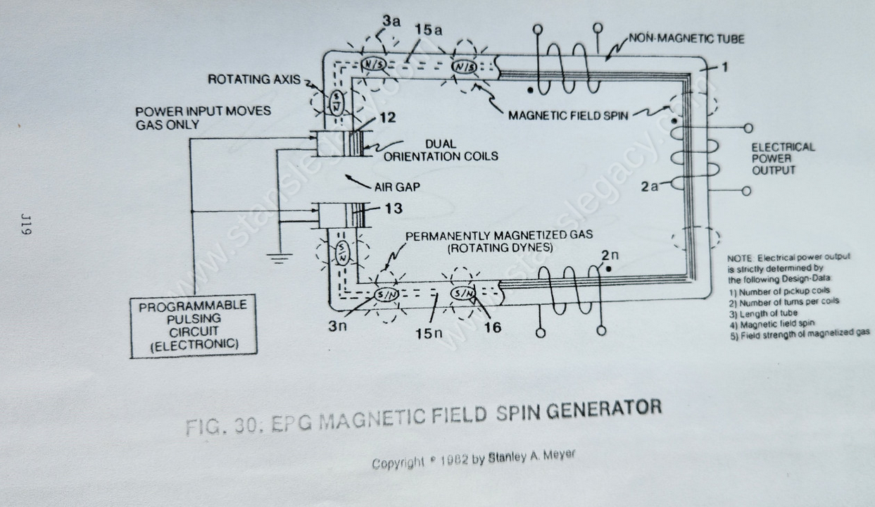](https://stanslegacy.com/uploads/images/gallery/2024-10/HkrFdxXxmCQmMROW-image-1729623833109.png)Placing **dual orientation coils** (12/13) on opposite ends of a **circular non-magnetic tube** (1) supporting a series of **pickup coils** (*2a xxx 2n*)... said hollow tube being filled with permanently magnetized particles of gas... said circular assembly forming an air gap between said orientation coils, as illustrated in Figure 30 as to Figure 30ZC and Figure 30ZD.| [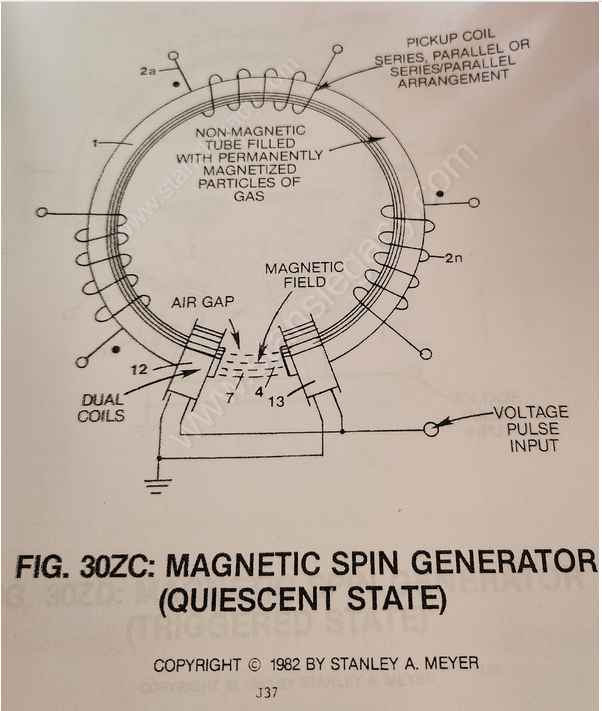](https://stanslegacy.com/uploads/images/gallery/2024-10/c7eoS45eOW683JwQ-image-1729624530181.png) | [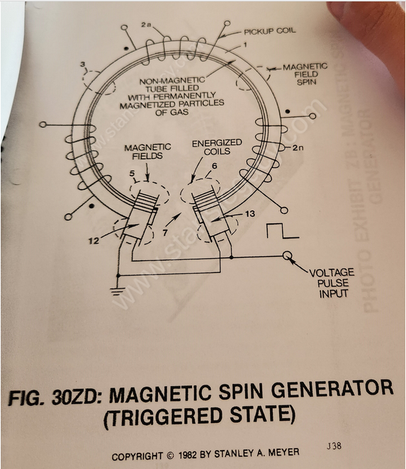](https://stanslegacy.com/uploads/images/gallery/2024-10/pv6T7I2yIhn5dHG5-image-1729623900399.png) |
By simply "switching on" said **variable gate circuit** (EE), a voltage pulse of a given duration is applied to both orientation coils simultaneously... producing **electromagnetic fields** (5/6) of equal magnitude in a North to South relationship to said **air gap** (7) as shown in Figure 30ZD.
--- [](https://stanslegacy.com/uploads/images/gallery/2024-10/pv6T7I2yIhn5dHG5-image-1729623900399.png)Once said **orientation coils** (12/13) become "electrically energized" and form **electromagnetic fields** (5/6), the **electromagnetic field** (7) across said **air gap** (4) of Figure 30ZC is terminated since said particle alignment of said **gas** (16) is "rotated" or "flipped" 90 degrees from point of **Quiescent**... forming **electromagnetic field** (3) of Figure 30 along the longitudinal axis of said **tubular structure** (1)... allowing said **electromagnetic field** (3) to expand, to pass through and beyond **pickup coils** (2a xxx 2n), as illustrated in Figure 30ZD. Once said **orientation coils** (12/13) become de-energized (switching off applied electrical power), said permanently **magnetized particles** (16a xxx 16n) now "rotate" or "flip" another 90 degrees to reform electromagnetic field (4) once again while simultaneously "switching on" said **electromagnetic field** (3). ---The collapsing **electromagnetic field** (3) passes through **pickup coils** (2a xxx 2n) forming a bipolar voltage pulse across said pickup coils.
##### MAGNETIC FIELD INTERACTION: [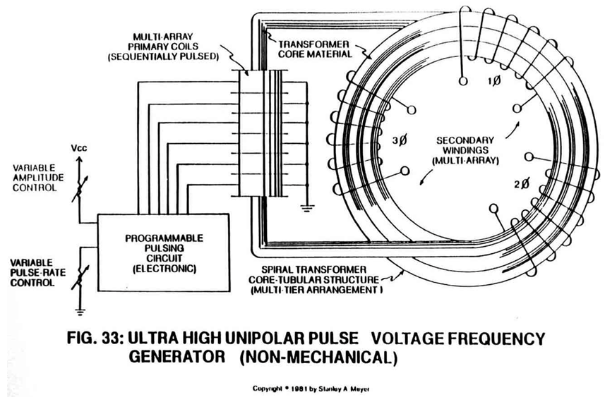](https://stanslegacy.com/uploads/images/gallery/2024-10/iA8DbdlGxg2gL0pE-image-1729624457766.png)To increase electrical power output further, simply **spiral-wrap** (1a xxx 1n) **non-magnetic tube** (1) through said **pickup coils-array** (2a xxx 2n), as illustrated in Figure 33. The spiral-wrap configuration increases the number of **magnetic flux lines** (*magnetic field*) surrounding the tubular leg, "cutting" or "passing" through said **coil-array** (2a xxx 2n). ##### POWER INPUT vs. POWER OUTPUT: Permanently magnetized particles of gas prevent electromagnetic coupling between said **orientation coils** (12/13) and said **pickup coils** (2a xxx 2n).Power input rotates or spins said particles of gas to produce an **oscillating magnetic field** (3).
#### ELECTRICAL POWER CONVERTER: The **Magnetic Spin Generator** becomes an A.C. electrical generator when the pickup coil-array is series-wrapped in a Right-Hand to a Left-Hand relationship. D.C. electrical output occurs when the coil-array is wrapped in the same direction. Orientation coils can be either pulsed by a D.C. and/or A.C. electrical power input. Electrical power conversion D.C. to D.C., D.C. to A.C., and/or A.C. to A.C. are obtainable.