| [](https://stanslegacy.com/uploads/images/gallery/2024-10/XjFBmgimCge8AATu-image-1729265842805.png) | [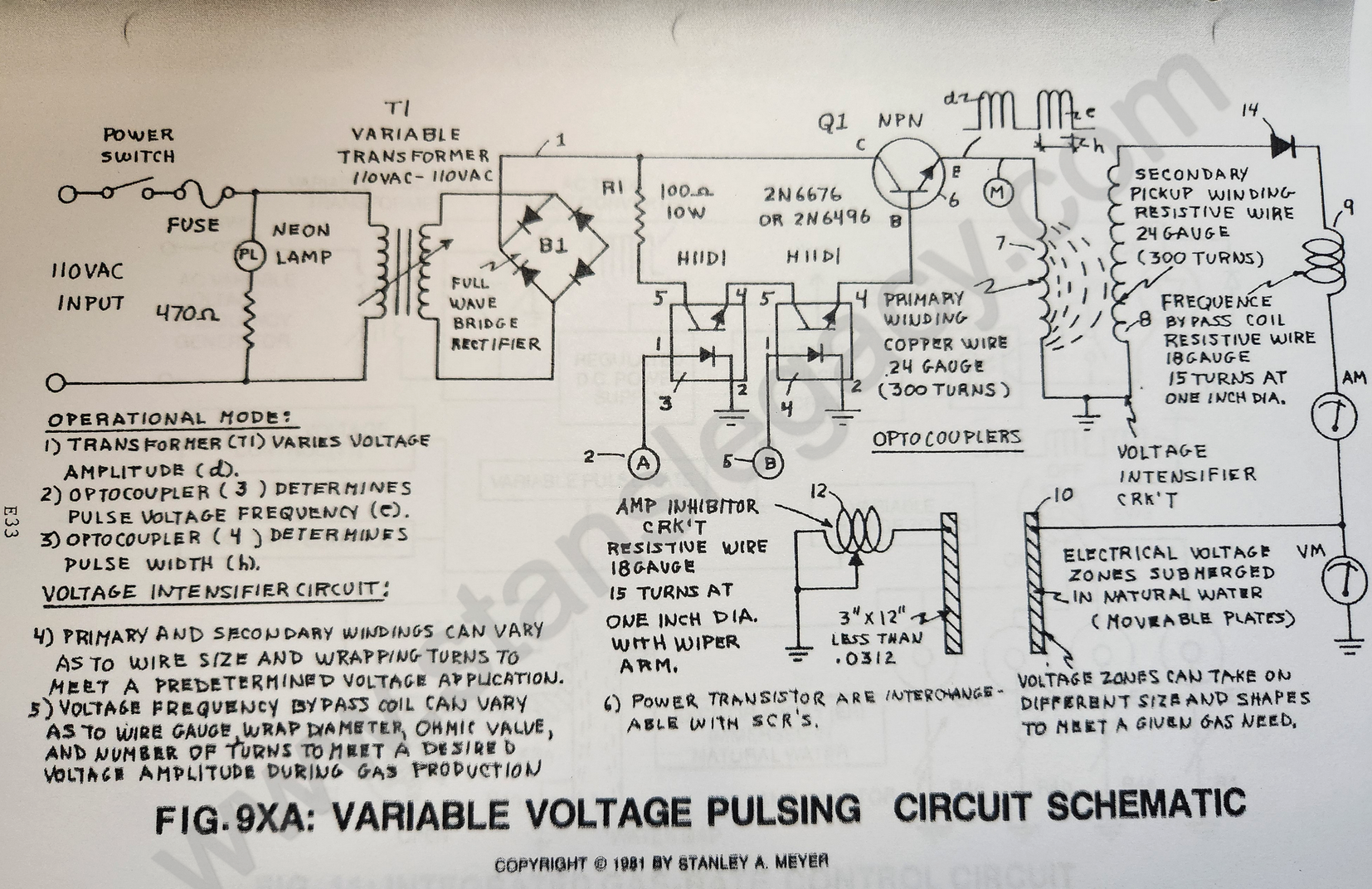](https://stanslegacy.com/uploads/images/gallery/2024-10/l16N0eiYU2kdSwXM-image-1729045722557-28-36.png) |
**Purpose:** To form opposite Electrical Voltage Zones while restricting amp flow during the Electrical Polarization Process (splitting the water molecule by way of Voltage stimulation).
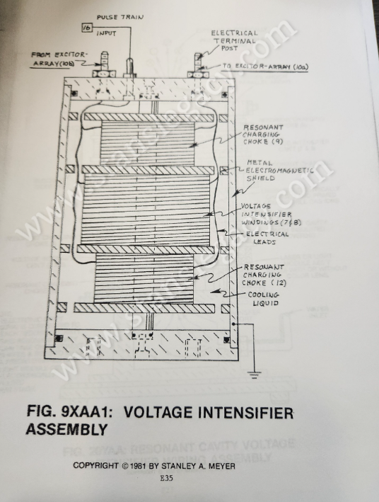
##### Component Interaction: **Secondary Pickup Winding (42):** The **resistive wire-coil** (42) allows a voltage potential (electromagnetic induction process) to form across said **pickup-coil** (42) while the resistive value (Ohm value) of said coil-wire acts as a resistor which opposes electron flow from said **circuit electrical ground** (48). > **Scientific Fact:** Since electrons are Negative Electrically Charged, electron flow (amp flow) always moves toward positive electrical potential... if allowed. **Block Diode (14):** Since **Blocking Diode** (14) conducts electricity in one direction "ONLY" (direction of schematic arrow), electron flow or movement toward said **pickup coil** (42) is prevented during said Positive Voltage Potential formation. [](https://stanslegacy.com/uploads/images/gallery/2024-10/CwBCD5eWdC7PdMTU-image-1729562258820.png)**Resonant Charging Choke (43):** Said **Resonant Charging Choke** (43) is a Modulator Inductor which sets up an oscillation of a given charging frequency (voltage pulsing rate) with the effective capacitance of a pulse-forming network in order to charge a line to a high voltage. See Modern Dictionary of Electronics 6th Edition by Rudolf F. Graf. The resistive value of said **Charging Choke** (43) acts as a resistor... preventing amp flow still further. **Electrical Voltage Zones (44/45):** Said High Voltage Output from said **Resonant Charging Choke** (43) forms a Positive Electrical Voltage Pulse Potential (voltage zone) across said **voltage surface area** (45) immersed in natural water, see step-charging graph 16A as to 20YA Section AA again. > **Scientific Fact:** Stainless Steel Material T304 forming said **voltage zone** (45) does "NOT" chemically interact with liberated hydrogen, oxygen, and ambient air gases in natural water when exposed to a voltage potential during amp restrictions. **Capacitance:** Capacitance value is formed between said **conductor plates** 44/45 (conducting medium between two plates) of natural water is relatively high.Capacitance opposes any change in circuit voltage.
A voltage change is delayed until the stored charges can be altered through current flow... if allowed.
Component arrangement of said **Voltage Intensifier Circuit** 9XA as to 20YA retards or prevents amp flow. > **Scientific Fact:** Distilled water is an insulator to the flow of amps; natural water has less than 20ppm of any type of contaminates and maintains a high dielectric constant.**Amp Inhibitor Component (47):** Another **Resonant Charging Choke** (47) is placed between said **negative voltage zone** (44) and said **circuit electrical ground** (48) to help maintain capacitance value (voltage level) within the Resonant Cavity during voltage pulsing.
The resistive value of said **wire-coil** (47) acts as a resistor while performing in like manner as a **Resonant Charging Choke** (43).| [](https://stanslegacy.com/uploads/images/gallery/2024-10/l16N0eiYU2kdSwXM-image-1729045722557-28-36.png) |
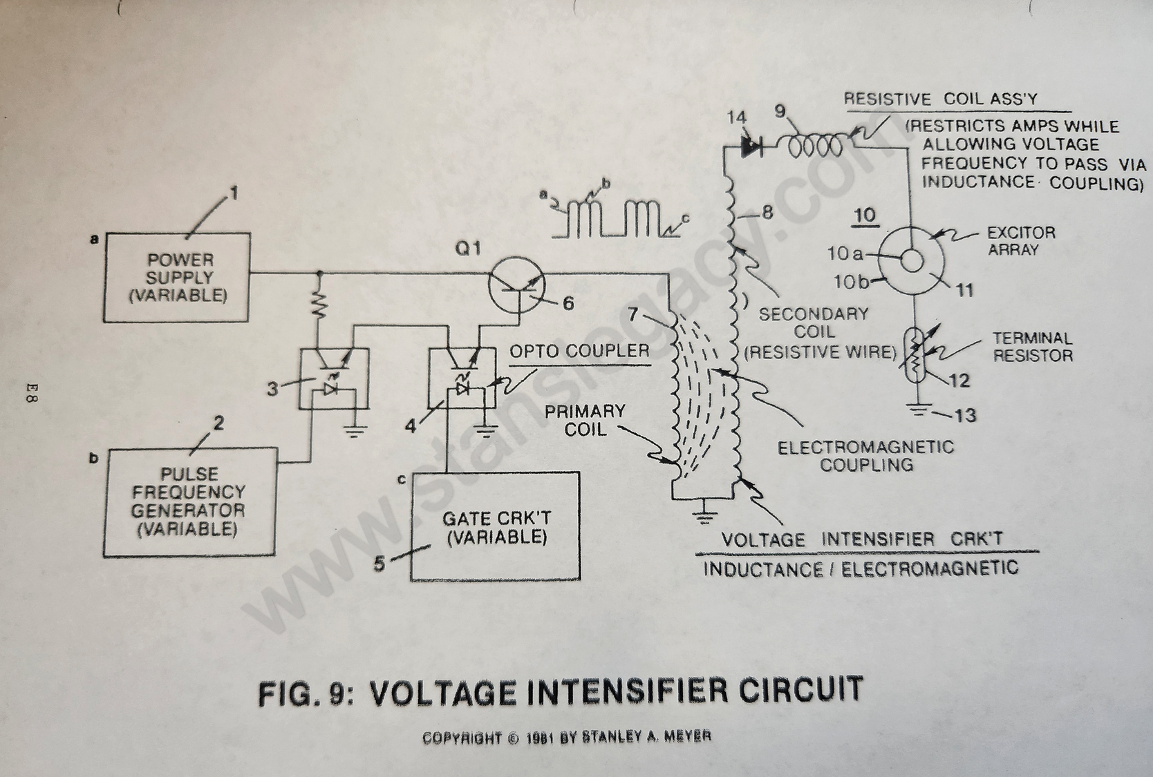
Any type of conventional A.C., to D.C. or D.C. power supply (*non-regulated*) where an adjustable voltage range from less than one volt to 110 volts and up (*first-stage to voltage attenuation*).
#### B) VARIABLE PULSE VOLTAGE FREQUENCY GENERATOR: **Purpose:** Not to allow a constant voltage source to be applied to excitor array (*voltage zones*) while attenuating voltage amplitude for gas-rate control. **Circuit Stage:** (1) (2) as to (3) of Figure 9 [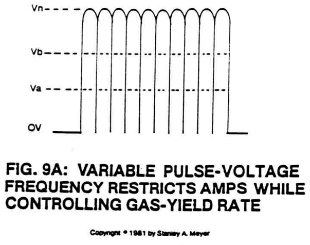](https://stanslegacy.com/uploads/images/gallery/2024-10/F03tn30nrr9rfxCn-image-1729266106655.png) **Optocoupler** (3) is a photosolation switch that when triggered by **pulse frequency generator circuit** (2) causes **power supply voltage** (1) to be attenuated as per Figure 9A, setting up a pulse voltage frequency.By varying the triggering rate of said **pulse generator** (2) from 1HZ to 1MHZ, said **pulse voltage frequency** (9A) is likewise varied.
--- [](https://stanslegacy.com/uploads/images/gallery/2024-10/jhHck3myrBaFiXPW-image-1729048345958-12-20.png) Phototransistor of said **optocoupler** (3) now allows said pulse **voltage frequency amplitude** (Va-Vn of Figure 9A) to be varied from less than one volt to over 110 volts via said **variable power supply** (1). **Circuit Function:** [](https://stanslegacy.com/uploads/images/gallery/2024-10/F03tn30nrr9rfxCn-image-1729266106655.png)The variable **pulse voltage frequency** (9A) is adjusted to keep amp flow restricted during first-stage to amp restriction by allowing said **voltage amplitude** (Va-Vn of Figure 9A). The variable **pulse voltage frequency amplitude** (Va-Vn of Figure 9A) is directly related to hydrogen gas production on demand (*second stage to voltage attenuation*). Both above said functions can be performed simultaneously or apart. #### #### #### C) VARIABLE GATE CIRCUIT: **Purpose:**To switch off and on said generated **pulse voltage frequency** (9A) at a variable time rate while maintaining said **voltage amplitude control** (Va-Vn of Figure 9A).
**Circuit Stage:** (4) (5) as to (6) of Figure 9. **Optocoupler** (4) is another photoisolation switch that when triggered by **variable gate circuit** (5) (*a second variable triggering circuit*) causes said **pulse voltage frequency wave form** (9A) to be altered as shown in Figure 9B.The gated pulse train (16, **on time**) as to (17, **off-time**) is adjustable from 1% to 100% duty time.
| [](https://stanslegacy.com/uploads/images/gallery/2024-10/F03tn30nrr9rfxCn-image-1729266106655.png) | [](https://stanslegacy.com/uploads/images/gallery/2024-10/cciAsdzIq5mJ3P2q-image-1729266167366.png) |
**To reduce the number of voltage pulses**, simply reverse the pulse-train frequency.
Once the **gated pulse train** (15) is set as to maximizing gas production, the **duty-cycle pulse** (15) is now varied from one duty-pulse per second **alternation** (15a) to one hundred duty-pulses per second **duration** (15n). The **voltage amplitude** (Va-Vn of Figure 9A) remains variable as to gas needs. Of course, **optocoupler** (4) gates on power transistor Q1 as herein described. ##### Circuit Function: 1. The adjustable pulse-train simply "concentrates" or time-regulates the applied **pulse voltage frequency** (9A), allowing for higher voltage amplitude (*third-stage to voltage attenuation*). 2. The **variable gated-pulse** (15) is now adjusted to reduce amp flow further while allowing **voltage amplitude** (Va-Vn) and **pulse voltage frequency** (9A) to be adjusted to "tune-in" for higher gas-yields (*second stage to voltage attenuation*). #### D) VOLTAGE INTENSIFIER CIRCUIT: **Purpose:** To step up **power supply voltage** (1) while maintaining said **variable voltage amplitude** (Va-Vn) control, said **variable pulse frequency** (9A) control, said **variable gate** (9B) control, and performing a *third, fourth, and fifth step to amp restriction*.| [](https://stanslegacy.com/uploads/images/gallery/2024-10/F03tn30nrr9rfxCn-image-1729266106655.png) | [](https://stanslegacy.com/uploads/images/gallery/2024-10/cciAsdzIq5mJ3P2q-image-1729266167366.png) |
As power transistor Q1 is actuated to produce **variable waveform** (9B), the **output wave form** (9B) is now superimposed onto a primary coil wrap around a secondary coil of greater size (*more turns of wire*), forming a voltage intensifier transformer, see Figure 9.
[](https://stanslegacy.com/uploads/images/gallery/2024-10/jhHck3myrBaFiXPW-image-1729048345958-12-20.png)The primary coil is composed of copper wire, whereas the secondary coil is composed of resistive wire. Both types of wire are coated with an insulated material to prevent electrical shorting.
Opposite to the input-to-output leads, the two said coiled wires are joined together to form an electrical ground.Only transformer paper is used to wrap said coils.
By way of **transformer-action** (*electromagnetic coupling*), said **waveform** (9B) is now transferred to said secondary coil, performing voltage amplification while said pulse-train remains the same.
The step-up voltage amplitude is, however, directly related to **power supply voltage** (1) and attenuated during gas production. The pulse-train is likewise attenuated as herein described. **To help prevent amp leakage from occurring during gas production,** said resistive wire is used to retard amp flow through said **secondary coil** (8) voltage potential is developed across said **pick-up coil** (\*) leads (*third stage to amp restriction and fourth-stage to voltage attenuation*.) The air space between said primary and said secondary coils provides a step-gap to amp flow since no electrical "junction" or "connection" exists inside said air-gap (*fourth-stage to amp restriction).* ##### Circuit Function: The amp restricting functions occurring prior to said transformer-action prevents "power drop" during pulsing operations under load (*fifth-stage to amp restriction*). #### E) HIGH FREQUENCY VOLTAGE BYPASS COIL: **Purpose:** To restrict amp flow while allowing voltage potential to pass through said bypass coil (9 of Figure 9) via electromagnetic induction coupling. [](https://stanslegacy.com/uploads/images/gallery/2024-10/jhHck3myrBaFiXPW-image-1729048345958-12-20.png)**Circuit Stage:** (8) as to (9) As pulse voltage potential is developed across said **secondary coil** (8) leads, said developed voltage pulses are now allowed to pass through and beyond said **bypass coil** (9) by way of electromagnetic inductance.**Inductance coupling** occurs when said voltage pulses generate an oscillating magnetic field around said bypass coil (9). The incoming voltage pulse creates a magnetic field that passes through said **coil** (9) windings.
Once the applied incoming voltage pulse is terminated, as herein described, the magnetic field now collapses, allowing said collapsing magnetic field to pass through said **coil** (9) once again during said voltage off-time. Amp restriction occurs since said **coil winding** (9) is composed of resistive wire (*sixth-stage to amp restriction*). **Circuit Function:** a) To duplicate incoming voltage pulse train while performing amp restriction without heat build-up. #### F) ELECTRICAL VOLTAGE ZONES: **Purpose:**To establish and set up **voltage zones** (10) of opposite polarity in natural water without inducing chemical oxidation.
[](https://stanslegacy.com/uploads/images/gallery/2024-10/wNgSJ1fymUzCkCof-image-1729266278109.png)**Circuit Stage:** (9) as to (10) The pulse voltage waveform (*mirror imaged of Figure 9B*) developed at said **bypass coil** (9) output lead is now transferred to stainless steel plates (*excitor array*) submerged in natural water.Due to the **skin-effect phenomenon**, voltage forms across said plates of Figure 9, forming voltage zones of opposite polarity. Switching off said voltage pulse eliminates said voltage zones.
Reapplying said voltage pulse re-establishes said voltage zones once again. Repetitive formation of said voltage pulses now establishes an oscillating voltage field between opposite polarity plates called **voltage zones** (ER).In addition, said voltage zones take on the geometrical shape of said material.
##### **Circuit Function:** **a.** The physical property of stainless steel T304 material is ideally suited since said material does "not" oxidize when exposed to liberated hydrogen and oxygen atoms in water having no voltage potential applied to said material.As per above said "operating conditions," lab certification tests show the decomposition rate of said stainless steel material at .0001/yr.
**b.** Chemical interaction is also held to a minimum since amps are being restricted (*as herein described*) in natural water having no more than 20 parts per mission of any type of contaminates (*seventh-stage to amp restriction*) **Rule of thumb:** Do not increase electrical conductivity of natural water by adding chemicals. **Gas production** occurs in all natural water, even the purest form of distilled water, when voltage potential is applied to its dielectric constant.**Remember:** Distilled water is an insulator to the flow of current (amps).
> **Point-of-Discovery:** > > If amps are being restricted during gas production, then voltage stimulation is dissociating the water molecule. This process is now called the "electrical polarization process," see Water Fuel Cell Technical Brief as to Exhibit AX (*taken from McGraw-Hill Encyclopedia of Science and Technology Volume 14, page 405*). --- #### **G) VOLTAGE CHAMBER:****Purpose:** To eliminate voltage leakage to surround water during gas production.
**Circuit Stage:** (10) as to (20 of Figure 9D)\*\* [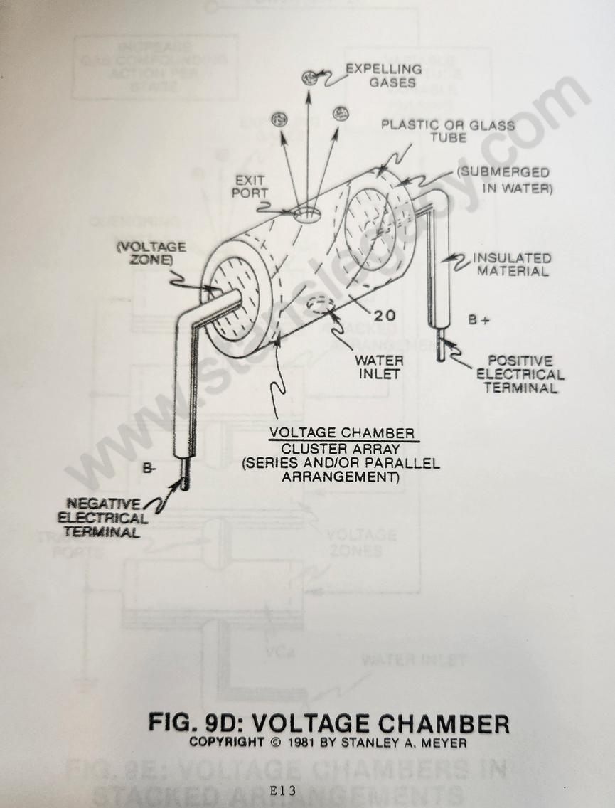](https://stanslegacy.com/uploads/images/gallery/2024-10/ppr59sTqG3hHbRdF-image-1729048789470-19-42.png)By simply surrounding said voltage zone with an electrical insulator (Teflon) such as plastic or glass (see 20 of Figure 9D), said applied voltage pulses retain a much higher voltage potential during gas production. Simply, said **insulator cavity** (20) seals off said voltage gap by preventing electrical leakage to said water supply.Voltage concentration is now accomplished during gas production.
**Circuit Function:** a) To maintain a higher voltage potential on said voltage zones by preventing electrical leakage beyond said voltage gap (sixth-stage to voltage attenuation). b) Said voltage chambers are relatively "small" or "tiny" in size and can be arranged in parallel or series array, as illustrated in Figure 9C, or stacked in series relationship (*exit port to inlet port*) for "**compounding gas production**" (*inducing particle impact into said voltage process*), as illustrated in Figure 9E. [](https://stanslegacy.com/uploads/images/gallery/2024-10/R3G8Tt2dMkN9KTih-image-1729276395263.png)c) To prevent electrical leakage from occurring outside said voltage chamber, simply use a plastic (insulator material) housing to form said fuel cell.
| **[](https://stanslegacy.com/uploads/images/gallery/2024-10/QEmus59m3g6OaIOS-image-1729048915680-21-49.png)** | [](https://stanslegacy.com/uploads/images/gallery/2024-10/4eKCvCSxilPQQzx1-image-1729048853633-20-49.png) |
**Purpose:** To increase gas production beyond voltage attenuation while keeping power loss to a minimum.
**[](https://stanslegacy.com/uploads/images/gallery/2024-10/QEmus59m3g6OaIOS-image-1729048915680-21-49.png)Circuit Stage:** (6) as to (7) (8) (9) (10) as of Figure 9C.To extend gas production beyond the limits of a **single** **excitor array** (10) (and voltage zones), simply add more excitor array (ER as to 10) to said gas producing process, as shown in Figure 9C.
Each **excitor-array** (10) is connected to the same circuit with said **voltage intensifier circuits** (7) (8) and (9), which, in turn, are **sequentially pulsed** (19) to minimize power loss during gas production. **Circuit Function:** 1. Said **sequential gate control circuit** (19) is variable to control gas production beyond said voltage attenuation controls (*seventh-stage to voltage attenuation*). 2. By variable pulsing circuit (1) (2) (3) (4) (5) as to (6) remains under power, however additional **excitor-array** (10) as herein described is added, power loss or drainage is held to a minimum (*ninth-stage to amp restriction*). --- #### **I) TERMINAL RESISTOR:****Purpose:** To provide ohmic balance between said **bypass coil** (9) and said **ground terminal** (13) to help eliminate electron deflection within said power circuit during gas production.
**Circuit Stage:** (9) as to (13) **Terminal resistor** (12 of Figure 9) is affixed to said **excitor-array** (10) on ground side (see Figure 9 again) to prevent counter electron deflection or movement within said **interfacing circuit** (8 as to 9). Said **terminal resistor** (12) is composed of resistive wire wrapped in a coil configuration, taking the shape of said **bypass coil** (9). Said **bypass coil** (9) and said **terminal resistor** (12) are the same in likeness. An adjustable terminal lead (wiper arm) is affixed, however, to said **terminal resistor** (12). **Circuit Function:** 1. Helps prevent distortion of said **pulse voltage waveform** (9B) during gas production. 2. Helps prevent transformer "**humming**" during power loading. 3. Said **terminal resistor** (12) can be adjustable to help "tune-in" gas production. #### **IA) VOLTAGE INTENSIFIER CIRCUIT: ELECTRONIC COMPONENT INTERACTION:****Purpose:** To utilize Resonant Charging Chokes to aid amp restriction.
**[](https://stanslegacy.com/uploads/images/gallery/2024-10/jhHck3myrBaFiXPW-image-1729048345958-12-20.png)Circuit Stage:** (7) (8), (14), (9), (10) as to (11), (10B), (12) and (13). The electrical control circuit used to start and control the gas generation process is shown in the schematic diagram of Figure 9. This diagram consists of the major components required to control this process and its described in the order of process flow (*from left to right across the schematic*). **ELECTRICAL DESCRIPTION OF COMPONENT:** [](https://stanslegacy.com/uploads/images/gallery/2024-10/4CdF2iRgpm6PC64B-image-1729266381003.png)The following is a description of each of these electrical components, their interconnections, their functions and the processing signals generated to disassociate the water molecule by way of voltage stimulation. The water fuel cell is also one of the major components of this circuit with its physical make-up, calibration, volume, and characteristics of water (*dielectric constant, capacitance, and electrical charge*). **SIGNAL FLOW:** 1. The **voltage intensifier circuit** (Figure 9) converts the **variable DC supply voltage** (1) into a continuous **high-frequency positive unipolar signal** (Figure 9B) to control the variable duty cycle pulse train (Figure 9B) to control the **power supply** (1). 2. The **high voltage pulse train** (16 of Figure 9B) is then coupled to the **stainless steel excitor plates** (10A) submerged in water, producing gas output. 3. By way of transformer-action (electromagnetic coupling), the step-charging effect of Figure 9B enhances the gas-yield by maintaining a stable voltage zone. **CONTINUOUS OPERATIONS:**The volume of gas from the fuel cell is now controlled by the variable duty cycle pulse train (one to one hundred percent). The variable DC power supply (1) serves as the optimum plate load of the excitors during resonant tuning.
##### CIRCUIT SETUP AND CALIBRATION The setup and calibration of this circuit is one of the major factors in the operation of this system and must be completed before use. The water fuel cell is filled with **water** (10 & 11), the excitor plates adjusted for the correct distance and volume, then connected to the voltage intensifier circuit (Figure 9). The circuit is then tuned to match the resonant characteristic of the total system by adjusting the pulse frequency generator (2) and the **series resonant charging choke-coil** (12). The amount of gas output from the water fuel cell is then adjusted by the **variable gate control circuit** (5) and the level of the **variable DC power supply** (1). --- ##### TRANSIENT STARTUP During the transient startup period, the **unidirectional diode** (14) is in its non-conducting state and isolates the water fuel cell from the **high voltage multiplying component** (8). This diode allows the fuel cell to take on a positive charge during each high positive voltage pulse. Also the diode prevents the fuel cell from discharging during pulse train off times. During the initial charging of the fuel cell, the **modulator inductor coils** (9 and 12) serve as a DC current limiter because of their resistive value (Resistive wire). The low "Q" resonant charging circuit consisting of **fuel cell** (10 and 11) in series with **choke-coil** (9 and 12) has the capability of storing electrical energy during each of the successive DC pulse inputs. The charge of the fuel cell is further enhanced by the **choke-coils** (9 and 12) during **diode** (14) disconnect times. As a result, a **step-charging effect** (voltage), as illustrated in Figure 9BB, is applied across the **fuel cell** (10). Also during pulsing operations, the impedance of the charging circuit increases, resulting in the reduction of current flow from the **high voltage drive circuit** (7 and 8).| [](https://stanslegacy.com/uploads/images/gallery/2024-10/2FbVfLFcwSScLY6T-image-1730214117271.png) | [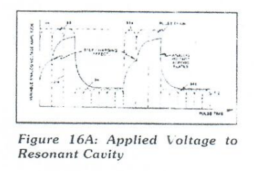](https://stanslegacy.com/uploads/images/gallery/2024-10/aynBsyXMHxv1nLEy-image-1730214293687.png) |
This step charging effect is also illustrated in Figure 16A.
##### CONTINUOUS OPERATIONS The volume of gas from the fuel cell is now controlled by the variable duty cycle pulse train (one to one hundred percent). The variable DC power supply (1) serves as the optimum plate load of the excitors during resonant tuning. #### J) ROTARY PULSE-VOLTAGE FREQUENCY GENERATOR:**Purpose:** To interface said pulsing circuit (Figure 9) with another type of power supply.
[](https://stanslegacy.com/uploads/images/gallery/2024-10/0piahrmjgpVCEhbi-image-1729266878909.png) **Circuit Stage:** (21) (22) (23) (24) (25) as to (4) (5) and (6) As shown in Figure 11A, the **variable amplitude pulsing circuit** (21) allows **armature coils** (22) to be electrically energized to produce **pulsating electromagnetic fields** (23) which are then rotated toward and through **pickup coils** (24), producing a variable A.C. pulse train. **Bounce network system** (25) converts said variable A.C. pulses to variable D.C. pulses. **Variable gating circuit** (4) (5) as to (6) simply switches off and on said D.C. pulse train, duplicating pulse voltage waveform (9B). [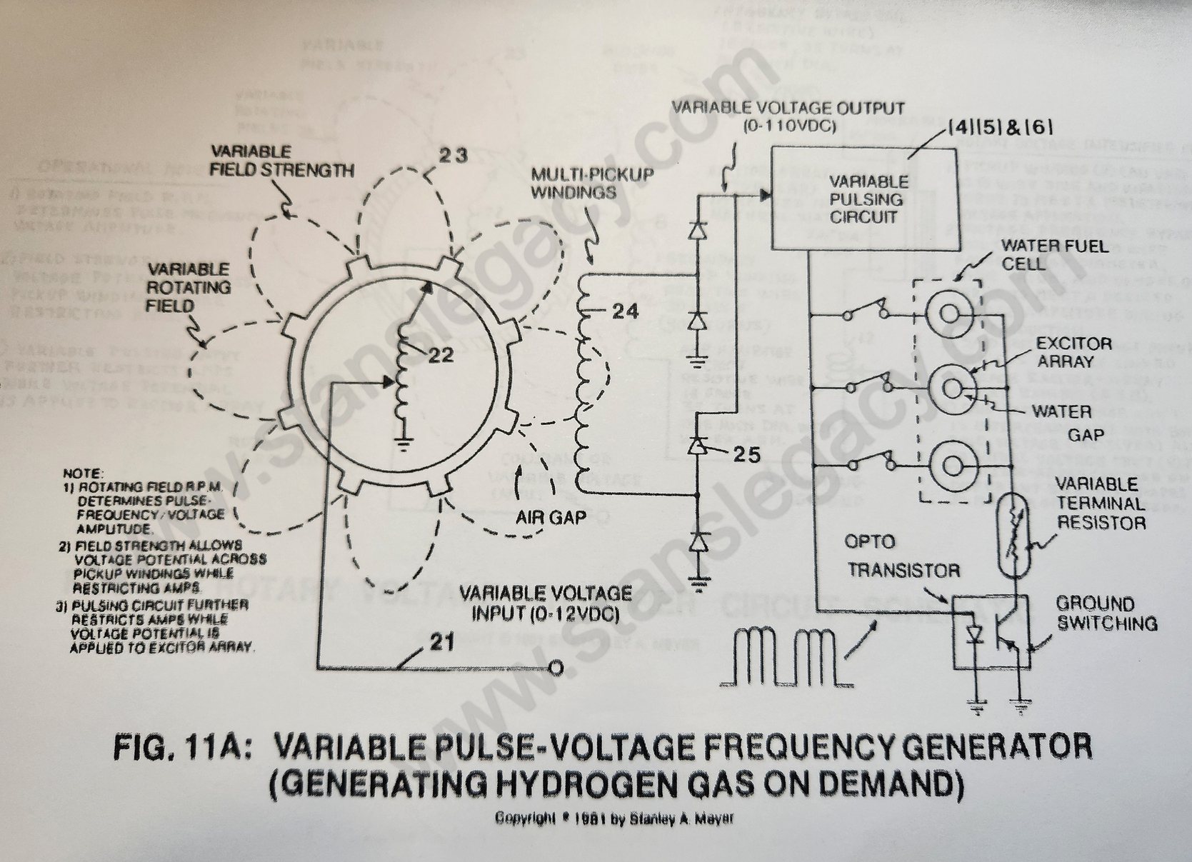](https://stanslegacy.com/uploads/images/gallery/2024-10/v4JUZ12ECaIJe4hb-image-1729049649399-34-03.png) **Circuit Function:** **a)** To adjust **magnetic field strength** (23) in such a way as to allow voltage potential only to be developed across said **pickup coils** (24) connected to said **gating circuit** (see Figure 9). Due to electrical "isolation," amp draw is now restricted since said magnetic field strength remains weak. (*tenth step to amp restriction*) **b)** To change said generated voltage pulses, simply vary the rotational speed of said armature. (*eighth step to voltage attenuation*) **c)** To vary voltage pulsing amplitude, simply vary the amplitude voltage of said **electrical power input** (21). (*ninth step to voltage attenuation*) **d)** To restrict amps still further by using resistive wire to form said pickup winding, see Figure 9XF and Figure 9XG.| [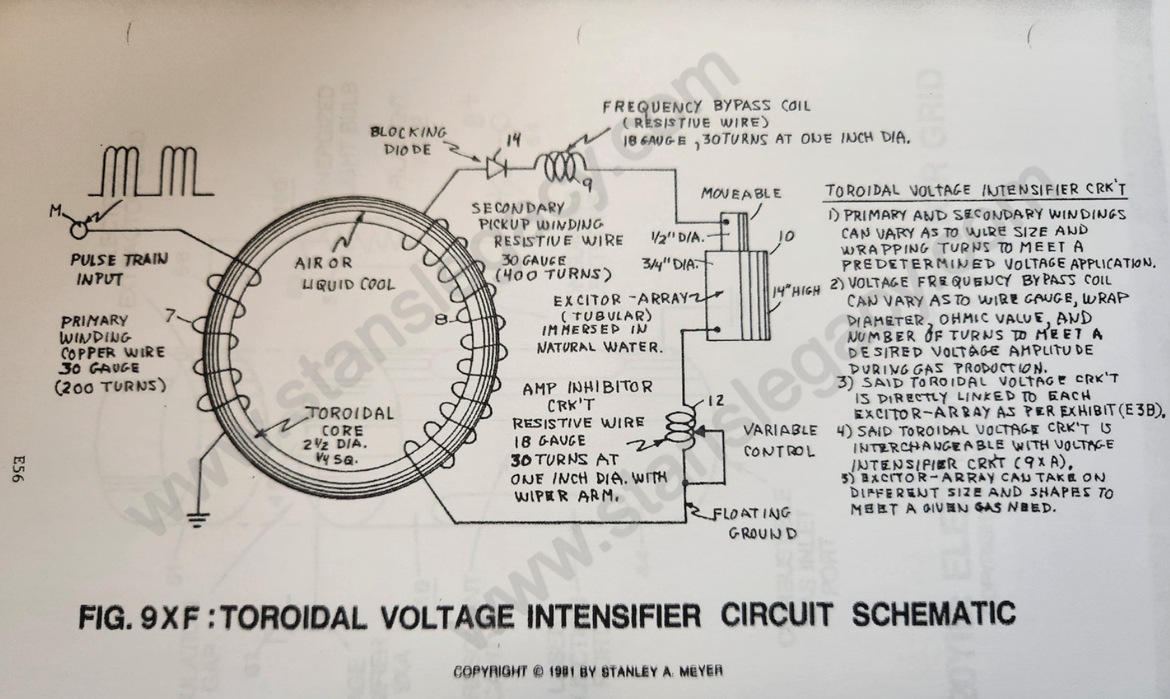](https://stanslegacy.com/uploads/images/gallery/2024-10/J7VYuMrE8ExOEwpJ-image-1729049778475-36-14.png) | [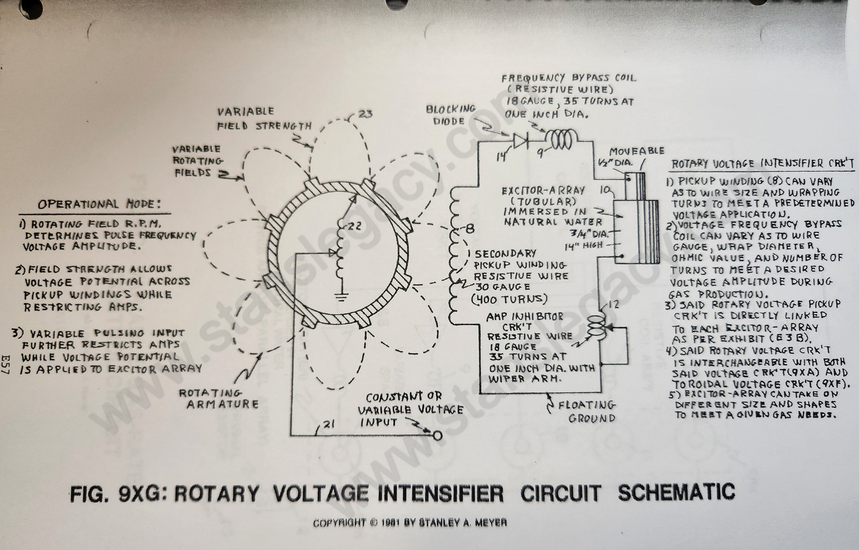](https://stanslegacy.com/uploads/images/gallery/2024-10/RxbTwBxeS1BcJaSf-image-1729049820426-36-56.png) |
| [](https://stanslegacy.com/uploads/images/gallery/2024-10/yFRt1SsQlgbh3jPC-image-1729266954621.png) | [](https://stanslegacy.com/uploads/images/gallery/2024-10/B0eH1Bru4Ei3jS0a-image-1729266961655.png) |
The fuel cell can produce more than 100cc/min of gases at one amp leakage.
--- #### **K) VOLTAGE VS PRIOR ART:** 1. Said fuel cell can operate continuously without excessive heat build. Cool to the touch. No heat sink is required. 2. Said stainless steel material needs not be replaced since decomposition rate (.0001/yr) is now negligible as compared to prior art. Said material has over 3200 hours of operating time and still maintains material specs. Prior art longevity, less than 100 hours. 3. Said fuel cell uses only natural water without chemical additives. 4. As to response time, said fuel cell "instantly" produces hydrogen gas on demand. 5. Voltage attenuation as to voltage amplitude is extremely broad range (one volt to over 5,000 volts) for high gas yield. Prior art limits gas production due to "amp arcing" that reduces electrode’s life. 6. Due to voltage attenuation, said **excitor-array** (ER) is extremely "small" and "lightweight." Prior art requires electrode mass to extend gas production. 7. Voltage Attenuation as to voltage amplitude is extremely "broad range" (one volt to over 5,000 volts) for high gas yield. Prior art limits gas-production due to "amp arcing" that reduces the electrode's life. 8. Portable voltage generators are relatively small and lightweight as compared to amp generators. 9. Said fuel cell sustains and maintains a high temperature hydrogen/oxygen flame beyond 5000F. Said flame-size is constant since control ability is limited to amp flow. Chemical fumes from said prior art keep flame temperature low. Prior art must use a gas-ignitor at all times to maintain said gas-flame combustion. 10. Said fuel cell uses nine ways (*steps to voltage attenuation*) to vary gas production. Prior art simply allows said amp flow to occur. 11. Said fuel cell uses ten ways (*steps to amp restriction*) to restrict amp flow. Prior art only uses a repetitive gate switch to switch on amp flow. 12. By using voltage attenuation to said fuel cell, ambient air from the outside is allowed to uniformly mix with said hydrogen and oxygen gases, reducing hydrogen gas burn-rate from 325 cm/sec to less than 47 cm/sec. 13. Ionization of said liberated gases can now take place by subjecting said gas atoms to a high-intensity voltage pulse. 14. Said ionized gases can now be subjected to flame combustion for applied energy yield (super charging flame temperature). 15. Since said prior art uses chemical additives (about 20% per volume) to reach maximum electrical conductivity (remember, distilled water is an insulator to amp flow), prior art creates a dead short condition that will not allow applied voltage potential to exceed several volts. Said prior art circuitry cannot compensate beyond said "dead-short" condition. Said fuel cell circuit not only overcomes said "dead-short" conditions but allows variable gas production, as herein described. 16. Said voltage circuit simply restricts amp flow (amp leakage) to a minimum while voltage parameters are varied. --- #### L) FUEL CELL MODE OF OPERABILITY: > In scientific quantitative analysis (*see Exhibit AX, McGraw-Hill Encyclopedia of Science and Technology Volume 14, page 489, paragraph 5*), said water molecule is known to take on polar charges. Said hydrogen gas being positively "electrically" charged, whereas said oxygen atom takes on a negative electrical charge (opposite polarity to said hydrogen atom at the same time). The net "electrical" attraction between said oppositely charged atoms of said water molecule is strong enough to "hold" said water molecule together. As herein described, said fuel cell technology (see Water Fuel Cell Technical Brief) simply overcomes said attraction force between said electrically charged atoms of said water molecule by forming voltage zones (of sufficient magnitude as to pull apart said charged atoms by way of opposite polarity attraction). The positive "electrically" charged hydrogen atom is being attracted to said negative "electrically" charged voltage zone; whereas, at the same time, the negative "electrically" charged oxygen atom is attracted to said positive "electrically" charged voltage zone, thereby complying with the opposite polarity attraction law of physics. By simply varying said voltage parameters on said voltage zones, said gas production can be quickly altered by doing the following: 1. By increasing voltage amplitude, which in turn increases opposite polarity attraction, causing greater gas production. 2. By varying said pulse voltage frequency in direct relationship to said variable voltage amplitude. 3. By varying said pulse-train (number of voltage pulses per gated pulse) in direct relationship to both variable voltage amplitude and variable gated pulse rate. 4. By sequentially switching (variable switching) power load to said exciter-array while performing all above said voltage functions. 5. By performing all above said voltage functions while performing said sequential switching in direct relationship to moving said voltage zones. 6. All above said control features may be operated separately, grouped together, or actuated together in a systematic way. #### M) AREAS OF ACCOMPLISHMENT: 1. Produce hydrogen gas economically since water is free. 2. Control the rate of gas production on demand with instant response. 3. Adjusting hydrogen burn-rate from 325 cm/sec to 42 cm/sec (co-equating fossil fuels) by using said water as a gas mixing regulator. 4. Sustaining and maintaining a hydrogen/oxygen flame regardless of fuel cell. 5. Developed quenching circuit to prevent spark-back into said fuel cell. 6. Distributing said fuel cell gases without spark ignition by developing said quenching tube technology. 7. Extended longevity of said stainless steel material as a lifetime component. 8. Developed a self-cleaning fuel cell by way of voltage application (preventing an oxidizing coat or film from being developed by retarding chemical interaction due to amp consumption), said voltage pulses performing said scrubbing action, said voltage pulse polarity being reversed periodically on said plates. 9. Directly using utility power without the aid of an auxiliary amp generator.Each above said "operating" features far exceed the limitations of said prior art
# Dual Voltage Attenuation Circuit # Resonant Cavity ##### N) Resonant Cavity: **PURPOSE:** To enhance hydrogen gas production beyond voltage attenuation by way of compounding-action (particle impact) **Circuit Stage:**Integrating dual-pulsing circuit (33) (34) (38) (39) (40) to voltage intensifier circuit (Figure 9) previously described), as shown in Figure 20C.
[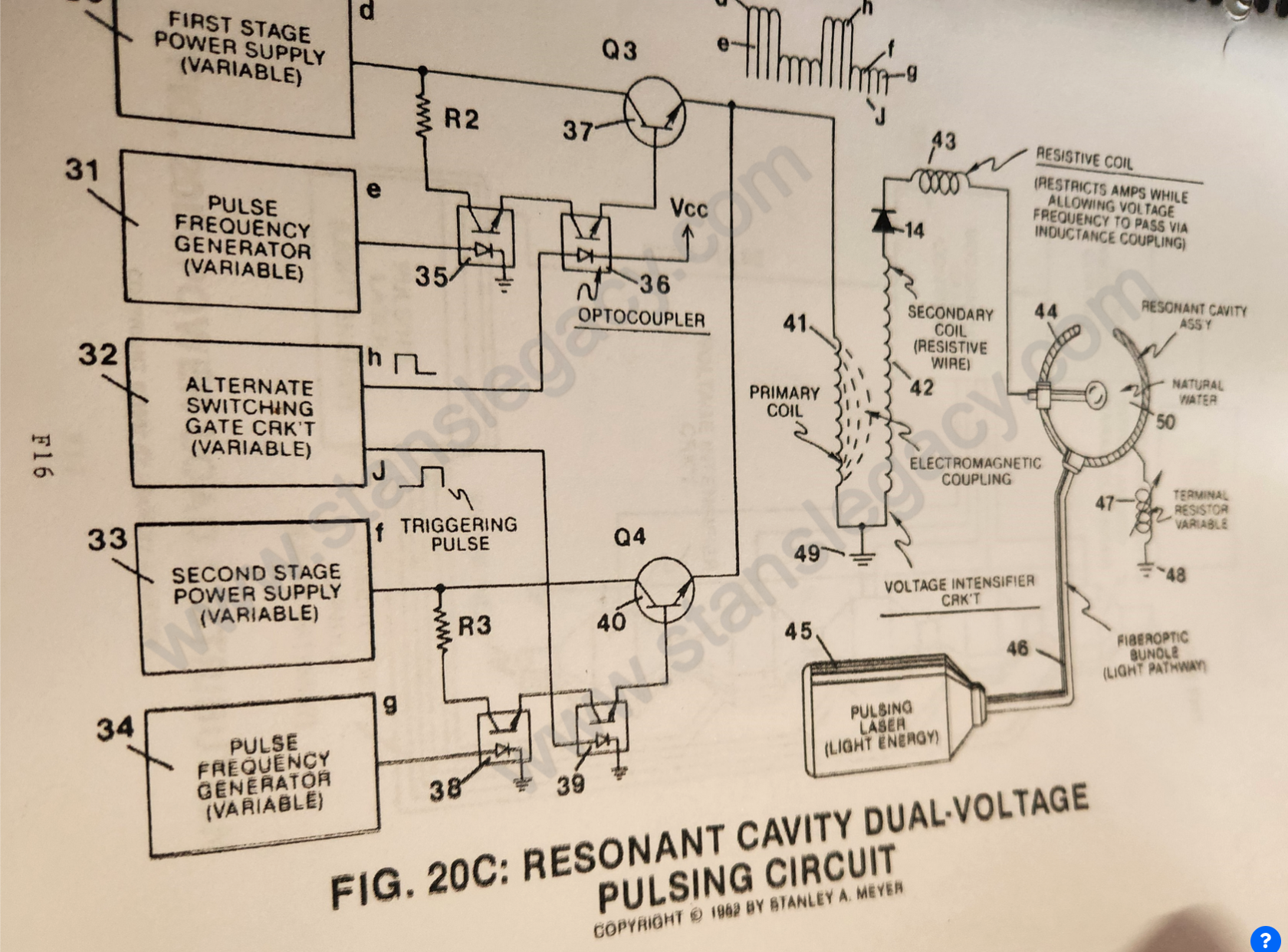](https://stanslegacy.com/uploads/images/gallery/2024-10/8giY0Hye9eZJ1C0K-image-1729052412177-20-08.png)As shown in Figure 20C. **variable gate circuit** (32) is a two-state switch device which is directly linked to both **opto-coupler** (36) and **opto-coupler** (39). As (H) near ground or low state (0 volts), **opto-coupler** (36) is triggered on. allowing **pulse voltage frequency** (d) as to (e) to form. Once said **gate circuit** (32) changes state (low to high voltage or versa), trigger pulse (J) turns on **opto-coupler** (39) to form **voltage wave form** (f) as to (g). **Triggered pulse** (H) is now terminated, switching off said **wave form** (d) (e).Repeating said alternate gate switching produces **dual-voltage pulse-train** (51) of Figure (16).
[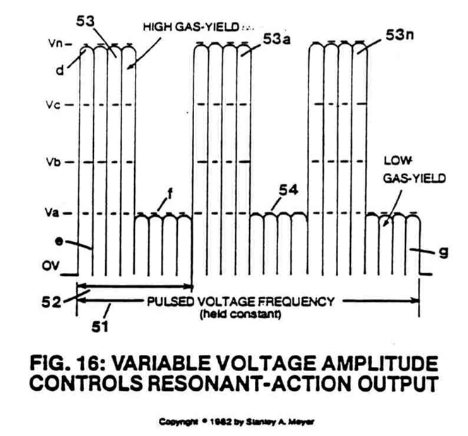](https://stanslegacy.com/uploads/images/gallery/2024-10/V1GF6JMkggg31Ckr-image-1729267018556.png) **Wave form** (d) (e) and **wave form** (f) (g) now **pulse-duty** (52) which is varied from one duty-pulse one hundred duty-pulses (establishing **pulse-train** 51) via **gate circuit** (32) *(tenth and eleventh steps to voltage attenuation)*.The reoccurring **duty-pulse** (52) is now attenuated to provide maximum gas-yield while minimizing amp flow.
**This is accomplished in several ways:**1. **Gated pulse** (H) as to **gated pulse** (J) is proportionally changed to "concentrate" or "expand" said applied voltages to said resonant cavity. Said **gated pulse train** (53, on time) as to (54, off time) is adjustable from 1% to 100% duty time.
As **on-time** (53) increases, **off-time** (54) proportionally decreases, allowing more **voltage pulses** (53) to be applied to said **resonant cavity** (44).
To reduce the number of **voltage pulses** (53), simply reverse the pulse-train adjustment of said **gate control circuit** (32).
Once the gated **pulse-train** (51) is set as to maximizing gas production, the **gated duty-cycle pulse** (52) is now varied from **one duty-pulse per second duration** (52a) to **one hundred duty-pulses per second duration** (52n) to help restrict amp flow.2. Said **voltage amplitude** (d) is varied to increase gas-yield. After said **voltage amplitude** (d) is stepped up, applied voltage range to said **cavity** (44) is from less than one volt to 5,000 volts or more.
3. Said **voltage pulse frequency** (e) is now varied from **1 Hz** to **1 MHz** and more, increasing gas-yield still further.
[](https://stanslegacy.com/uploads/images/gallery/2024-10/V1GF6JMkggg31Ckr-image-1729267018556.png)Said **voltage amplitude** (f) is varied to sustain and compounding-action within said **resonant cavity** (44). Said **voltage amplitude** (f) is adjusted as to cavity-size. An increase in voltage amplitude (f) is required as cavity-size increases. 4\. Once compounding-action is properly maintained, **voltage amplitude** (f) is adjusted "no" further to keep amp flow to a minimum (*twelfth step to voltage attenuation and eleventh step to amp restriction*).Once step up, **voltage range** (f) is the same as **voltage range** (d), one volt to 5,000 volts or more.
**Caution:** Said **voltage amplitude** (d) should never be less than said **voltage amplitude** (f) in order to maintain said compounding action.
5. Said **voltage pulse frequency** (g) is now adjusted from 1 Hz to 1 MHz or more to reduce amp flow still further while maintaining said compounding-action.
6. Said **variable gate circuit** (55) of Figure 20D is now retrofitted to said **dual-pulsing circuit** 20C to extend gas production beyond the limits of a single resonant cavity, keeping power loading to a minimum while adding another gas control feature.
| [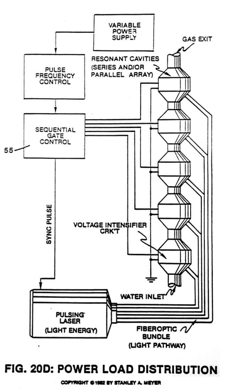Figure 20D](https://stanslegacy.com/uploads/images/gallery/2024-10/rrn3DYKgMU8J9mUg-image-1729267106297.png) | [](https://stanslegacy.com/uploads/images/gallery/2024-10/8giY0Hye9eZJ1C0K-image-1729052412177-20-08.png)Figure 20C |
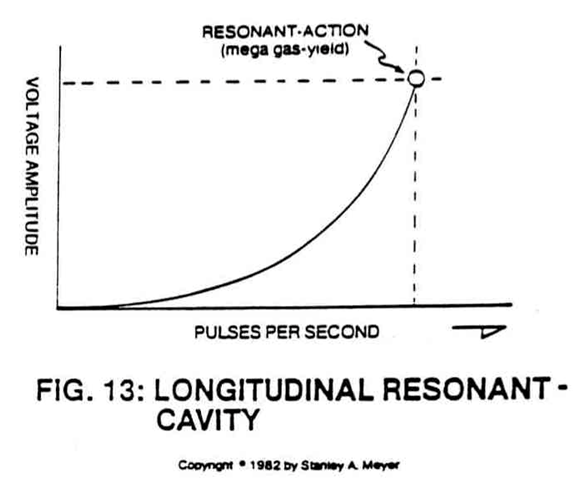
Said **resonant cavity** (44) can take on different shapes and sizes to meet a predetermined gas need. Spherical and longitudinal resonant cavities are examples.
> To disassociate said water molecule by way of voltage stimulation as previously described. See Section A through Section M.To momentarily entrap said liberated gas atoms to impart or subject a physical force (particle impact) on said water molecule being split apart. This process is called compounding-action or "**resonant-action**" since said liberated atoms are moved or oscillated in a uniform manner during gas production.
To start, sustain, and maintain said **resonant-action** during **gas-yield attenuation**.
To set up a variable pulsing circuit capable of "tuning-in" resonant action regardless of shape and dimensional size of said **resonant cavity** (44).
And to attenuate said voltage pulses (*up to and beyond 5,000 volts*) to cause said liberated gas atoms to reach **ionization state**.
# Operational CommentsTo start said compounding-action (resonant action) simply attenuate said voltage pulses while increasing said voltage amplitude.
Once resonant-action is established and said pulsing circuits adjusted for minimum amp flow, simply adjust said voltage amplitude controls to vary gas production and trigger gas ionization by way of particle collision
> (see Exhibit BX, *Encyclopedia of Chemistry,* \[Hampel/Hawley\], Third Edition, Page 585). #### #### **O) Laser Injected Resonant Cavity:** **PURPOSE:** To enhance hydrogen gas-yield beyond said voltage parameters and said compounding-action (resonant-action) prior to gas ignition. And to help cause said liberated gas atoms to reach said state of gas ionization. **Circuit Stage:** (45) (46) as to (44) in reference to said **high intensity voltage pulse** (53) (54) of Figure (16).| [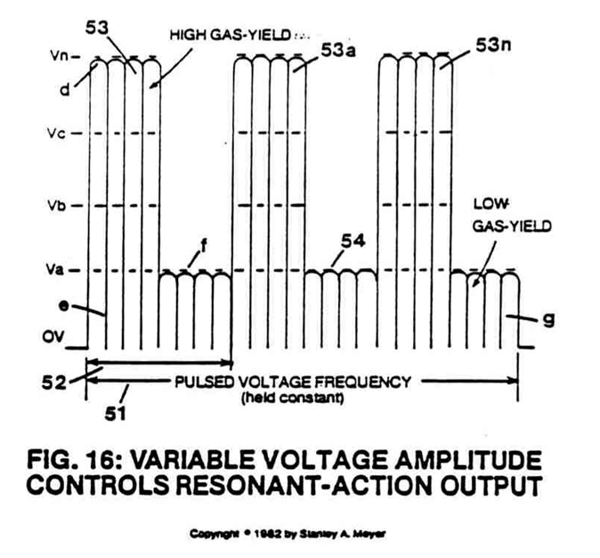](https://stanslegacy.com/uploads/images/gallery/2024-10/v66F69ECWqDbSCDG-image-1729267180900.png) | [](https://stanslegacy.com/uploads/images/gallery/2024-10/8giY0Hye9eZJ1C0K-image-1729052412177-20-08.png) |
Ionized gas build-up per cavity-stage causes greater gas-yield to occur prior to gas-ignition or utilization.
Said laser or light energy is pulsed to maintain said compounding action within said resonant cavities.
[](https://stanslegacy.com/uploads/images/gallery/2024-10/v66F69ECWqDbSCDG-image-1729267180900.png)The absorbed electromagnetic energy (**light-energy**) (45) by said atoms forming said water molecule also helps disrupt electrical mass equilibrium of said water molecule atoms when said water molecule atoms are subjected to said **high-intensity voltage pulse** (53) (54) of Figure (16). *(See [Exhibit BX](https://stanslegacy.com/books/wfc-technical-brief-extended-design-specs/page/exhibit-bx1 "Exhibit BX1") again)*. **Laser assembly** (45) can be any type of conventional laser that operates in the visible and/or ultraviolet region. In application, semiconductor lasers are used in packaged form to transmit said generated laser or light energy to said resonant cavity.Said semiconductor laser package is variable pulsed from 1Hz to 1KHz or higher to help trigger gas ionization during said resonant-action process.
# Resonant Cavity Mode of Operability > In scientific quantitative analysis (see Exhibit AX, *McGraw-Hill Encyclopedia of Science and Technology,* Volume 14, Page 489, and Exhibit BX, *The Encyclopedia of Chemistry* (Hampel/Hawley), Third Edition, Page 585), said water molecule is known to take on polar charges and that gas ionization can take place under certain conditions. As herein described, said resonant-cavity fuel cell technology (*see Water Fuel Cell Technical Brief in reference to Section A through Section M*), simply encourages gas ionization (*over and beyond prior art*) of said water molecule atoms to increase gas-yield beyond said voltage attenuation prior to gas-ignition. **Gas ionization and utilization occurs in the following way:** 1. Said water molecule (*having polar charges as per Exhibit AX*) is subjected to a high-intensity voltage pulse that separates said water molecule atoms by way of opposite polarity attraction law of physics, liberating hydrogen and oxygen gases from water. Ambient air gases dissolved in said water are also being released during said voltage process. Said fuel cell is a multi-gas generator. 2. As said liberated gases are exposed to a pulsating laser or **light-emitting source** (45), said liberated gases absorb said light radiation, causing many liberated gas atoms to lose electrons, said changed atoms now become positively charged ions. Said electromagnetically primed (atoms absorbed photon energy) hydrogen atom may now accept said liberated electron, forming a negative ion (*see Exhibit BX*). 3. In both cases, said formed ions are now subject to motion or deflection by said **high-intensity voltage pulses** (53/54). **Compounding action** (resonant action) now occurs since said ions' movements are directly related to said voltage pulse frequency. By simply increasing said pulse voltage frequency, said ions' movements increase. By decreasing said pulse voltage frequency, said ions' movements slow down. By keeping said pulse voltage frequency constant, said ions' movements remain constant. By increasing said voltage pulse amplitude, ion movement speeds up. 4. Since said ions are in motion, particle collision is now occurring when said ions' particles strike (physical impact or physical force) said water molecules undergoing said voltage separation, increasing said gas yield. 5. Particle collision also causes other liberated atoms to become ionized beyond the absorption of said light radiation, liberating more electrons inside said **resonant cavity** (44). 6. Since said liberated electrons have a negative electrical charge, said positive voltage pulse now causes said electrons to be moved uniformly with said pulse voltage frequency, aiding said compounding action (resonant action) still further. 7. To increase gas yield still further, said ionized or charged particles of gases are now injected into other resonant cavities undergoing above said resonant action process (*see Figure 20D as to Figure 20C*).| Figure 20D [](https://stanslegacy.com/uploads/images/gallery/2024-10/rrn3DYKgMU8J9mUg-image-1729267106297.png) | Figure 20C [](https://stanslegacy.com/uploads/images/gallery/2024-10/Ntr9gVfP79ZhyB5D-image-1729208719847.png) |
**Geometrical gas production** (Figures 13, 14, and 15) occurs when said resonant cavities are stacked exit port to inlet port or as a singular cavity unit. Said geometrical gas rate peaks out (or stops) when water flow rate into said resonant cavity becomes constant **or** reduced during gas production.
| [](https://stanslegacy.com/uploads/images/gallery/2024-10/UHag3KJU3laR8vfZ-image-1729267349199.png) | [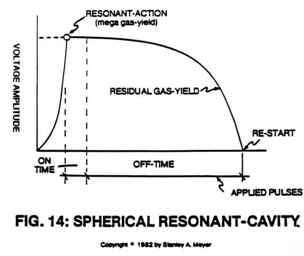](https://stanslegacy.com/uploads/images/gallery/2024-10/YRrvqkciN3BjhtEs-image-1729267354109.png) | [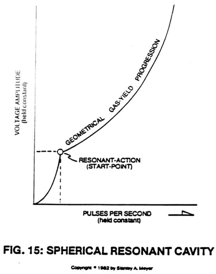](https://stanslegacy.com/uploads/images/gallery/2024-10/4LOpBa06u0V64gBh-image-1729267359551.png) |
8. To increase and encourage greater particle collision (*particle impact*), **accelerator tube** (56) of Figure (20A) is placed between said resonant cavity stages (*see Figure 20 and 20D*).
[](https://stanslegacy.com/uploads/images/gallery/2024-10/rpdvva5TruoVc6vB-figure-20a.png)Said expelled charged gases (movement of gases between cavity units) move toward, through, and beyond oppositely electrically charged plates or **voltage zones** (57 of Figure 20A) which are periodically spaced inside said **transfer tube** (56). By repeating said **gas attraction process** (20A) many times, said charged gas particles increase in velocity since **sequential gate circuit** (58) applies greater voltage potential per **gas attraction stage** (57).| [](https://stanslegacy.com/uploads/images/gallery/2024-10/TET1EbNXib6wqvi1-image-1729209597958.png) | [](https://stanslegacy.com/uploads/images/gallery/2024-10/rrn3DYKgMU8J9mUg-image-1729267106297.png) |
Increasing particle velocity directly increases gas yield to the next resonant cavity stage. Adding more **accelerator tubes** (*56a through 56n of Figure 20B*) per **resonant cavity stage** (see Figure 20) increases gas yield still further (see Figure 20B again).
| [](https://stanslegacy.com/uploads/images/gallery/2024-11/rSKHKZ4scwVii3fa-image-1731728633289.png) | [](https://stanslegacy.com/uploads/images/gallery/2024-11/JFjodXtc2ARHt8V3-image-1731728639739.png) |
Varying **gate switch circuit** (58) is another way to control gas production on demand (*fourteenth step to voltage attenuation*).
Sequentially switching off and on **accelerator tube array** (56a through 56n) (*parallel or series hookup*) is another way to control gas production on demand (*fifteenth step to voltage attenuation*).
Figure 20A - Gas Accelerator Tube [](https://stanslegacy.com/uploads/images/gallery/2024-10/rpdvva5TruoVc6vB-figure-20a.png) 9\. To prevent electrical discharge of said particles of gas when said **resonant cavity** (44) and said **gas attraction zones** (57) are submerged in natural water, said fuel cell housing is composed of an electrical insulating material such as plastic or spun glass.Electrical **positive** and **negative terminal surfaces** are coated with an insulating material as shown in Figure 9D.
| [Figure 9B](https://stanslegacy.com/uploads/images/gallery/2024-10/E3WkFIz6ixMM2AS4-image-1729263474263.png) | Figure 9D [](https://stanslegacy.com/uploads/images/gallery/2024-10/QC2eysc4GQKb7rKQ-image-1730306143914.png) |
| [](https://stanslegacy.com/uploads/images/gallery/2024-10/ft9jUGKL86bKoSc9-image-1728664731359.png) | [](https://stanslegacy.com/uploads/images/gallery/2024-10/8giY0Hye9eZJ1C0K-image-1729052412177-20-08.png) |
The resonant cavity fuel cell can produce more than 115-cc/min of gases at one amp leakage.
# Dual Voltage Resonant "Q" Electron Flow VS Voltage Amplitude VS Voltage Frequency - To form opposite Electrical Voltage Zones while restricting amp flow during the Electrical Polarization Process (splitting the water molecule by way of voltage stimulation). # DUAL VOLTAGE RESONANT "Q" #### **Electron Flow vs Voltage Amplitude vs Voltage Frequency:**In reference to Voltage Intensifier Circuit 9XA as to dual-voltage schematic 20YA and pulse voltage waveform 16A/20YA Section AA, the following operational parameters exist:
[](https://stanslegacy.com/uploads/images/gallery/2024-10/teWQHV77FyNS7NVn-image-1729532146629.png) #### **Electronic Interfacing Circuit:** - **Secondary Pickup Winding** (resistive wire coil) (42) - **Blocking Diode** (14) - **Resonant Charging Choke** (resistive wire coil) (43) - **Resonant Cavity Inner Surface** (45) (forming a Positive Electrical Voltage Zone), - **Resonant Cavity Outer Surface** (44) (forming a Negative Voltage Zone) - **Voltage zones surface area** (44/45) form the Capacitance value of said **Resonant Cavity Assembly** (4) of Figure 12. Natural Water inside said **Resonant Cavity Assembly** (44/45) provides the dielectric value between said **voltage zones** (44/45), **resonant charging choke** (47) to electrical ground forms and completes the **Voltage Intensifier Circuit** 9XA as to 20YA.| [](https://stanslegacy.com/uploads/images/gallery/2024-10/ZAhFd74xUdz1mzin-image-1729267471403.png) | [](https://stanslegacy.com/uploads/images/gallery/2024-10/l16N0eiYU2kdSwXM-image-1729045722557-28-36.png) |
**Scientific Fact:** Since electrons are negatively electrically charged, electron flow (amp flow) always moves toward positive electrical potential... if allowed.
--- ### **Block Diode (14)** Since **Blocking Diode** (14) conducts electricity in one direction "ONLY" (*direction of schematic arrow*), electron flow or movement toward said **pickup coil** (42) is prevented during said **Positive Voltage Potential** formation. # Dual Voltage Resonant "Q" - Part 2 ### **Resonant Charging Choke (43)** Said **Resonant Charging Choke** (43) is a Modulator Inductor which sets up an oscillation of a given charging frequency (voltage pulsing rate) with the effective capacitance of a pulse-forming network in order to charge a line to high voltage. > See *Modern Dictionary of Electronics* 5th Edition by Rudolf F. Graf. The resistive value of said **Charging Choke** (43) acts as a resistor, preventing amp flow still further. ### **Electrical Voltage Zones (44/45)** [](https://stanslegacy.com/uploads/images/gallery/2024-10/ohbO0cHOpWHtIwXR-image-1729525485071.png) Said High Voltage Output from said **Resonant Charging Choke** (43) forms a Positive Electrical Voltage Pulse Potential (voltage zone) across **surface area** (45) immersed in natural water, see step-charging graph 16A as to 20YA Section AA again. --- > **Scientific Fact:** > Stainless Steel Material T304 forming said **voltage zone** (45) does **NOT** chemically interact with liberated hydrogen, oxygen, and ambient air gases in natural water when exposed to a voltage potential during amp restrictions. --- ### **Capacitance** Capacitance value is formed between said **conductor plates** 44/45 (voltage zones) since the dielectric value (the insulating or non-conducting medium between two plates) of natural water is relatively high. This opposes any changes in circuit voltage.A voltage change cannot occur until the stored charges can be altered through current flow... if allowed.
Component arrangement of said Voltage Intensifier Circuit 9XA as to 20YA retards or prevents amp flow.| [](https://stanslegacy.com/uploads/images/gallery/2024-10/l16N0eiYU2kdSwXM-image-1729045722557-28-36.png) | [](https://stanslegacy.com/uploads/images/gallery/2024-10/yRRy0MKUNLI1yHEm-image-1729045880432-31-14.png) |
**Scientific Fact:** Distilled water is an insulator to the flow of amps; natural water has less than 20ppm of any type of contaminates and maintains a high dielectric constant.
--- ### **Resistor Component (47)** Another **Resonant Charging Choke** (47) is placed between said **negative voltage zone** (44) and said **circuit electrical ground** (48) to help maintain the resistance value (voltage level) within the Resonant Cavity during charging. The resistive value of said **wire-coil** (47) prevents amp flow while performing in like manner as a Resonant Charging Choke. --- ### **Resonant Action as to Voltage Stimulation of the Water Molecule** Resonant Action occurs when the Voltage Intensifier Circuit 9XA as to 20YA set up a circuit condition whereby the **inductive** (43/45) and **capacitive reactance** (44/47) (or circuit impedance) components of said circuit have been balanced. The Circuit is "tuned" to resonance at a certain pulse voltage frequency (reaching resonant "Q")... allowing voltage stimulation of the water molecule... performing the Electrical Polarization Process at **Resonant "Q."****Scientific Fact:** The ability of an inductor and a capacitor in a series-resonant circuit delivers a voltage several times greater than the input voltage.
--- ### **Resonant Cavity Structure vs Applied Pulse-Voltage** By simply varying the applied voltage amplitude in direct relationship to a variable pulse voltage frequency, the Resonant Cavity Structure can take on different shapes to maximize voltage stimulation of the water molecule to release hydrogen gas under control means.Voltage range from zero to 5,000 volts; pulse-voltage frequency range from zero to one megahertz; amp flow being restricted to a minimum value.
--- ### **Dual Voltage Resonant "Q"****Low Amplitude Pulse Voltage Frequency** (54) is injected between **Pulse Voltage Frequency** (53) to keep an electrical charge on said water molecule during Resonant "Q."
# Hydrogen Gas Gun To utilize or trigger the atomic energy-yield of water on demand. # Hydrogen Gas Gun Technology **G16** **Objective:** To utilize or trigger the atomic energy-yield of water on demand. **Voltage interaction with the water Molecule:** to applied Voltage Graph Figure 20FB **NATURAL STATE** Prior to Voltage stimulation, the water molecules are **randomly** (A) dispersed throughout the water medium inside said Resonant Cavity Fuel Cell, as shown in Figure 20YAA as to Figure 2 and Figure 3.| [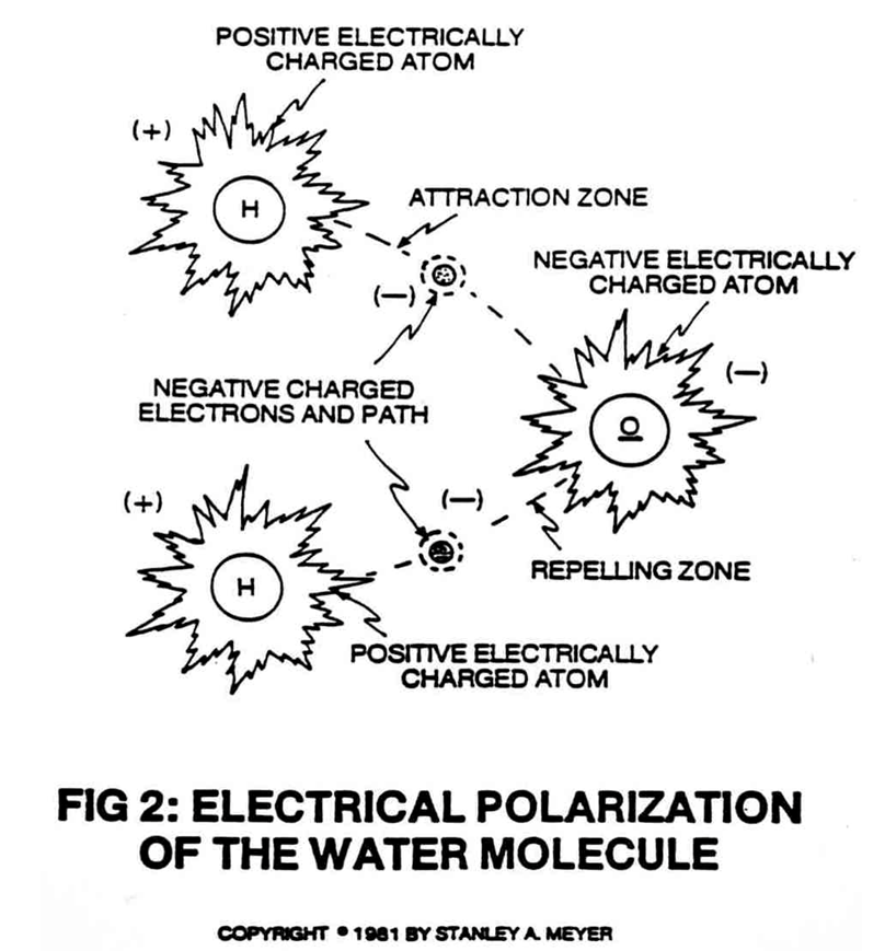](https://stanslegacy.com/uploads/images/gallery/2024-10/rkGmmSNoL96p6UZ6-image-1729263840905.png) | [](https://stanslegacy.com/uploads/images/gallery/2024-10/x3GmGbroQNmcGzMW-image-1729263848423.png) |
| [](https://stanslegacy.com/uploads/images/gallery/2024-10/yRRy0MKUNLI1yHEm-image-1729045880432-31-14.png) | [](https://stanslegacy.com/uploads/images/gallery/2024-10/l16N0eiYU2kdSwXM-image-1729045722557-28-36.png) |
The **Step Charging Effect** (*across said excitor-plates*) causes the pulsing voltage potential to increase from a **low energy state** (A) to a **high energy state** (J) during each pulsing-train, as illustrated in Figure 20FB.
[](https://stanslegacy.com/uploads/images/gallery/2024-10/yHKotVDKYIEID5GY-image-1729131224050.png) Typically, the analog voltage range (voltage intensity) is from zero to 5,000 volts and above. The increasing voltage potential is always positive in direct relationship to negative ground potential during each pulsing-stage. Voltage polarity on said excitor-plates (voltage fields) remains the same during each pulsing-operations. Said positive and negative voltage fields (voltage zones) are formed simultaneously. **Water Molecule Alignment** Since the water molecule naturally exhibits opposite electrical fields (the two hydrogen atoms being positive electrically charged relative to the negative electrically charged oxygen atom), the **analog voltage pulse** (B) of Figure 20FB causes said random water molecules to spin and orientate themselves in reference to said voltage fields. The positive electrically charged hydrogen atoms of said water molecule being attracted to said negative voltage plate; while, at the same time, the negative electrically charged oxygen atom of the same water molecule is attracted to the positive voltage plate. Said opposite voltage fields are formed on opposite sides of said water molecules.| [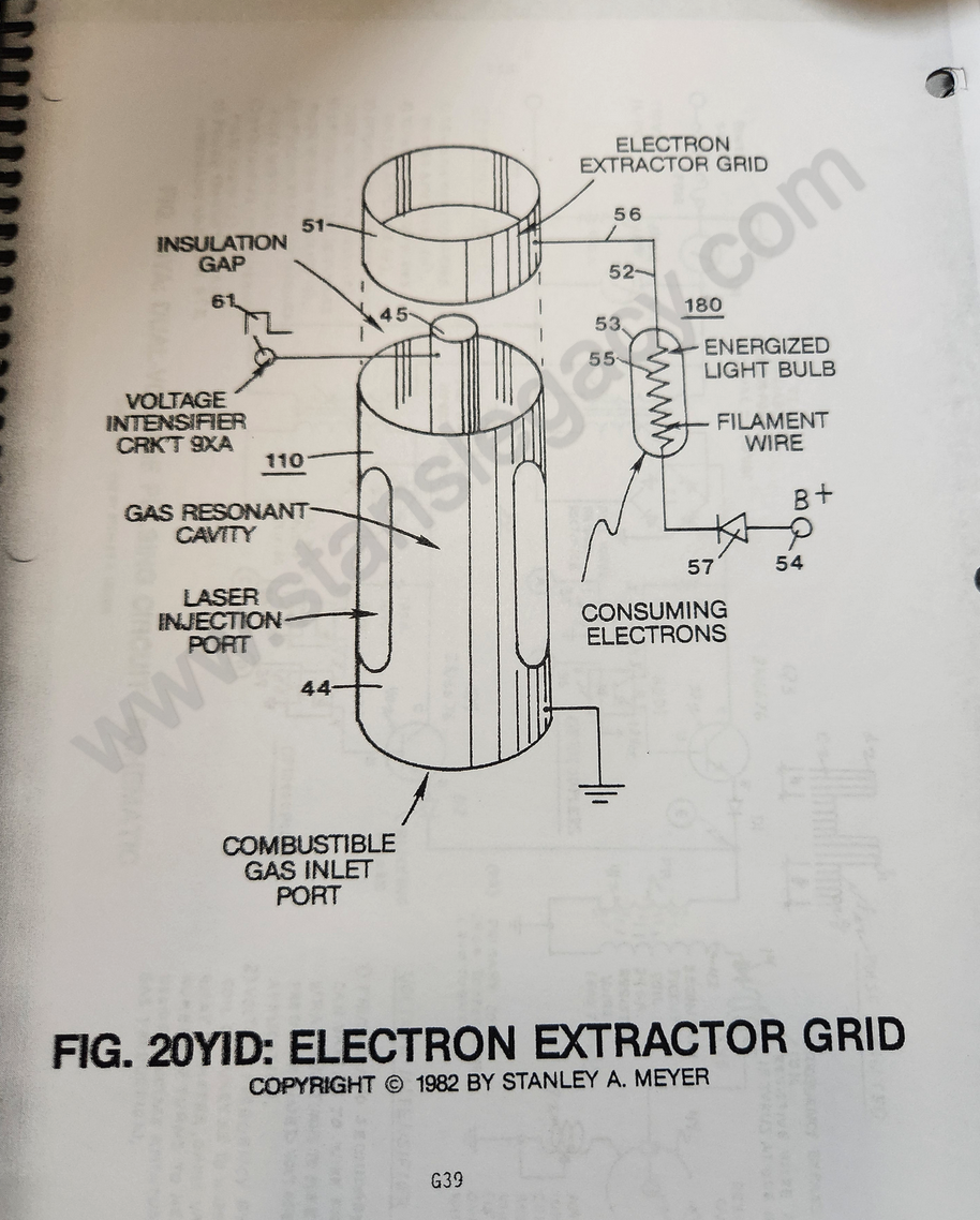](https://stanslegacy.com/uploads/images/gallery/2024-10/JSMUdXfT4X5zj0NB-image-1729046115351-35-10.png) | [](https://stanslegacy.com/uploads/images/gallery/2024-10/l16N0eiYU2kdSwXM-image-1729045722557-28-36.png) |
Several **gigavolts** (*billionth of a volt*) of applied power is all that is needed to initiate said molecular orientation. Amp restricting circuit 9XA as to 20YD allows said orientation process to occur.
--- **G17** **Polarization Charge** **Analog Voltage Level** (C) now causes the orientated water molecules to align themselves end to end between said voltage zones (excitor plates) in a linear direction since the positive voltage field intensity is also increasing in a linear function.The **Analog Voltage Level** (C) is now entering into the **microvolt range** (*millionth of a volt*).
Once molecular alignment occurs, molecular movement stops, as illustrated in Figure 3. Since the positive charged hydrogen atoms of said inline molecules are in opposite direction to the negative charged oxygen atoms, a polar charge now exists between said voltage zones.| [](https://stanslegacy.com/uploads/images/gallery/2024-10/rkGmmSNoL96p6UZ6-image-1729263840905.png) | [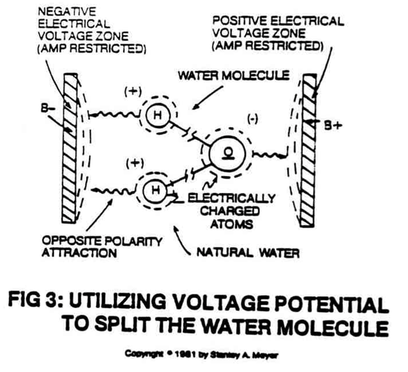](https://stanslegacy.com/uploads/images/gallery/2024-10/A5Vk50SWyd3krBxY-image-1729263915629.png) |
As the **Analog Voltage Level** (D) approaches the **Millivolt range** (*thousandth of a volt*), the stationary water molecules start to become elongated since said electrically charged atoms are being attracted toward opposite electrically charged voltage zones...disrupting mass equilibrium of said water molecule, as illustrated in Figure 3.
##### **Atom Liberation** [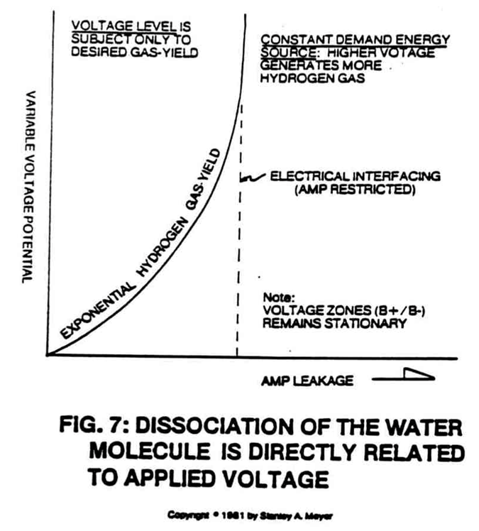](https://stanslegacy.com/uploads/images/gallery/2024-10/bpoVQut1tZE4PEkB-image-1729263943916.png)**Analog Voltage Level** (E) simply disrupts said electrical equilibrium of said water molecule undergoing said atom displacement. As the water molecule is exposed to said **voltage level** (E) the electrical charge of said atoms becomes greater in intensity... causing the covalent bonding (sharing electrons) between said atoms to be terminated or switch-off, as shown in Figure 2. The moving negative charged electron is being attracted toward the positive charged hydrogen atom while, at the same time, the negative charged oxygen atom repels said moving electron. This electrical stimulating effect now establishes the **Electrical Polarization Process**.Dissociation of the water molecule is directly related to applied voltage.
Higher voltage means higher gas-yield, as shown in Figure 7.The variable voltage fields can exceed hundreds of volts during fuel cell operations.
##### **Liquid to Gas Ionization** Once said **voltage potential** (F) reaches a certain threshold, the exposed water molecules and liberated hydrogen, oxygen, and ambient air gases start to ionize...losing or gaining electrons...causing atom destabilization...disrupting the electrical and mass equilibrium of said atoms, as illustrated in Figure 20K as to Figure 20F and Figure 20G.| Figure 20K | Figure 20F [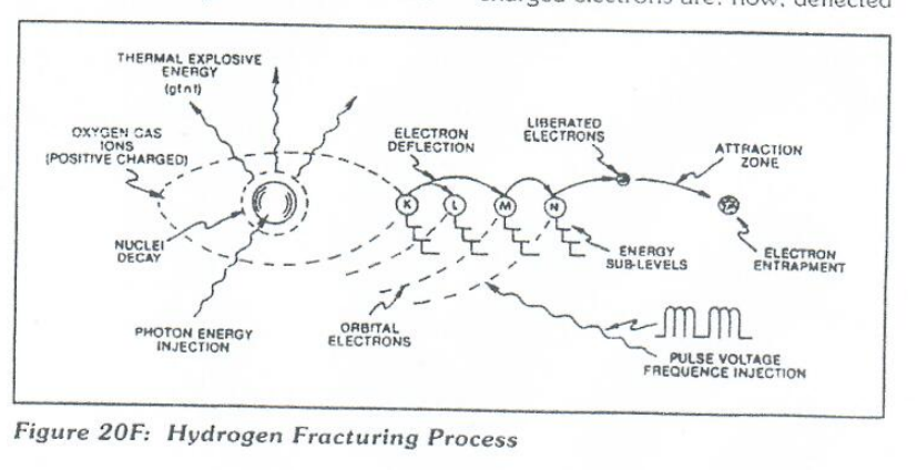](https://stanslegacy.com/uploads/images/gallery/2024-10/oZRWoLotIlKv3UtG-image-1729471836441.png) | Figure 20G [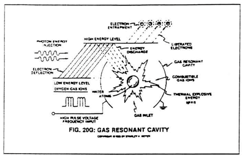](https://stanslegacy.com/uploads/images/gallery/2024-10/1npPuL12OpwGWPWk-image-1729267642775-07-20.png) |
Several thousands of volts trigger said ionization state.
--- **G18** ##### **Electrical Charging Effect**As the ionized gases (*being electrically charged*) are allowed to accumulate inside said Fuel Cell, the **electrical charging effect** (G) can be greater than said applied voltage...speeding up the **Electrical Polarization Process** still further.
##### **Particle Impact****Particle Impact** (H) occurs when the liberated ionized gases (Positive and Negative electrically charged gas atoms) are voltage deflected through the Electrical Polarization Process.
##### ##### **Laser or Photon Injection** To help reach gas ionization while highly energizing said atom nuclei (*see Figure 20F and 20K again*), **Laser or Photon energy** (I) of a predetermined wave length and pulse-intensity (see Figure 20FB Section B8) is exposed to and absorbed by said gas ions. [](https://stanslegacy.com/uploads/images/gallery/2024-10/1npPuL12OpwGWPWk-image-1729267642775-07-20.png)The highly energized nuclei causes electron deflection to a higher orbital state, as further illustrated in Figure 20F as to Figure 20G and 20K. **Laser-pulse** (or light-pulse) as well as light intensity is varied to match the absorption rate of said gas nuclei. ##### ##### **Atomic Destabilization** Continued exposure of said **gas ions** (F) to said **laser or light energy** (I) during **voltage stimulation** (A through H) prevents **atomic stabilization** (J). ##### ##### **Atomic Triggering on Demand** Since the liberated atoms are highly energized combustible gas ions, gas thermal ignition occurs when said combustible gas ions enter into and pass through **Optical Thermal Lens** assembly of Figure 20FC. The Electrically Charged and Laser primed combustible gas ions are expelled through and beyond a quenching circuit and reflected back and forth through a thermal heat zone prior to atomic breakdown beyond exiting ports. The **Deflection Shield** superheats (beyond 3,000 degrees F) the combustible gas ions while said exiting-ports are small enough to allow gas pressure to form inside said thermal zone.The atomic energy-yield from water is simply controlled by varying the applied **voltage pulse-train** (53a xxx 53n) since said thermal-lens assembly is self-adjusting to the flow-rate of said ionized and primed gases.
--- **G38/39** ##### **ELECTRON EXTRACTOR GRID AND RELATED CIRCUIT** T[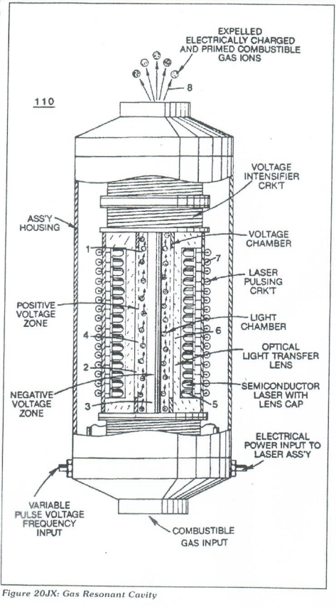](https://stanslegacy.com/uploads/images/gallery/2024-10/4uQ0Ao5CT4RXyfkk-image-1729524980060.png)o further stimulate and help the **ELECTRON ENTRAPMENT PROCESS** beyond the atomic level (taking away and capturing the liberator electrons during the Hydrogen Fracturing Process) (*see Figure 206 as to Figure 20F, once again*), an **ELECTRON EXTRACTOR GRID** (51) is placed on top of and in space relationship to said **Gas Resonant Cavity Structure** (110), as illustrated in Figure 20YID as to Figure 20JX. The **Electron Extractor Grid** (51) is attached to an **electrical circuit** (180) that allows **electron flow** (56) to pass to an **electrical load** (53) by electrical **wire** (52) when a **positive electrical potential** (54) is placed on opposite side of said **electrical load** (53) ...**electrical load** (53) being a typical light bulb or amp consuming device. As the **positive electrical potential** (54) is switched on or pulse-applied, the negative charged electrons liberated from the **Hydrogen Fracturing Process** are drawn away from said **Gas Resonant Cavity** (110 of Figure 20 JX) and enters into said **light bulb** (53) (*by way of opposite polarity attraction*) having **resistive filament wire** (55). As said **moving** **electrons** (56) interact with said **resistive wire** (55) am consumption (*consuming amps*) takes place by way of heat dissipation in the form of light energy.To help prevent electron oscillation or deflection during the **Hydrogen Fracturing Process**, said amp consuming **electrical circuit** (180) can be directly connected to said Gas Resonant Cavity **positive electrical voltage zone** (45), as illustrated in schematic 20IE.
| [](https://stanslegacy.com/uploads/images/gallery/2024-10/JSMUdXfT4X5zj0NB-image-1729046115351-35-10.png) | [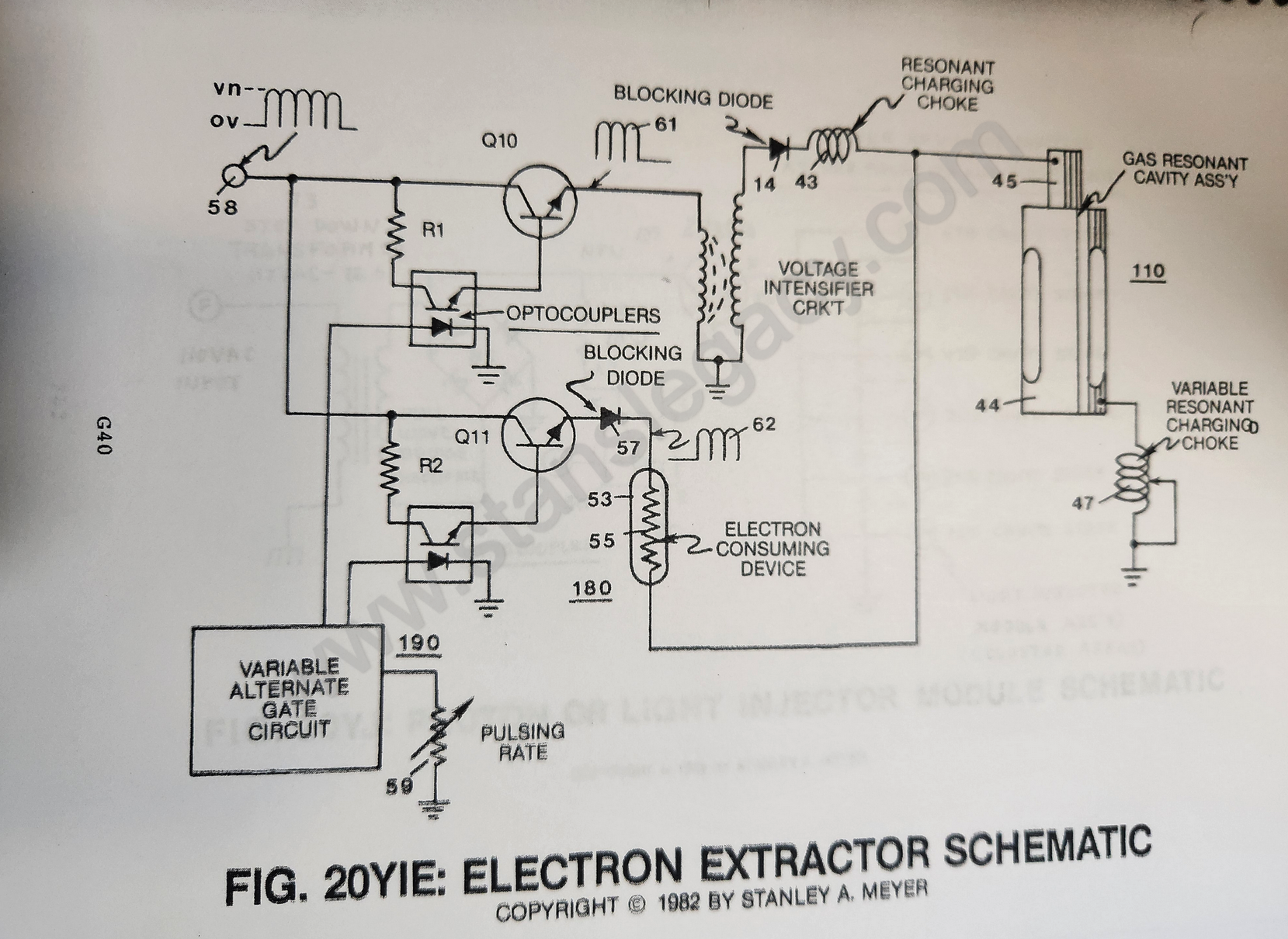](https://stanslegacy.com/uploads/images/gallery/2024-10/8qlZWt6M3sksLVfU-image-1729046916688-48-33.png) |
| [](https://stanslegacy.com/uploads/images/gallery/2024-10/IcznI3upYm6itJFn-image-1729045267854-21-04.png) | [](https://stanslegacy.com/uploads/images/gallery/2024-10/PgvTgZXMM4xge0nm-image-1729046825104-47-01.png) | [](https://stanslegacy.com/uploads/images/gallery/2024-10/EHo3Ub2FWlqXN2Q9-image-1729046860662-47-37.png) |
| [](https://stanslegacy.com/uploads/images/gallery/2024-10/8qlZWt6M3sksLVfU-image-1729046916688-48-33.png) | [](https://stanslegacy.com/uploads/images/gallery/2024-10/JSMUdXfT4X5zj0NB-image-1729046115351-35-10.png) | [](https://stanslegacy.com/uploads/images/gallery/2024-10/7ZxTZ0aSxqk0rJzK-image-1729047448777-57-25.png) |
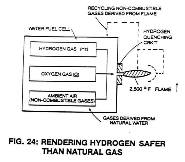
To develop and utilize a **hydrogen gas reclaim system** capable of performing water purification on demand without using chemical filters.
##### **Assembly Stage:** **Catalytic Dome Assembly** (10/30) positioned on top of and in space relationship to a Quenching Nozzle (20) affixed on top of and to a natural Water Fuel Cell, as illustrated in Figure 24 as to Figures 24SA, Figure 24SB, and 24SC.| Figure 24SA | Figure 24SB | Figure 24SC |
| [](https://stanslegacy.com/uploads/images/gallery/2024-10/H40XNTZkh9JH6UrX-image-1729264485208.png) | [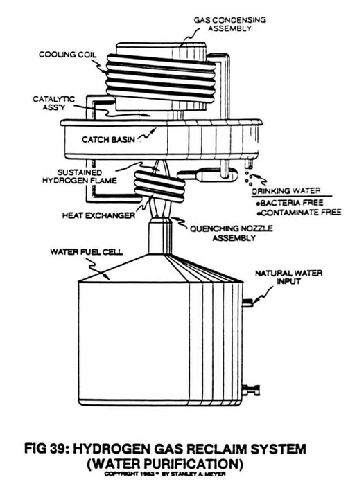](https://stanslegacy.com/uploads/images/gallery/2024-10/S1khIgN4tHvwcpGa-image-1729264594060.png) |
The gas mixing ratio of said Fuel Cell automatically adjusts the burn rate of **hydrogen gas from 325 cm/sec** to **42 cm/sec**, co-equating the burn-rate of natural gas, as illustrated in Figure 24 as to Figure Graph 23.
| [](https://stanslegacy.com/uploads/images/gallery/2024-10/H40XNTZkh9JH6UrX-image-1729264485208.png) | [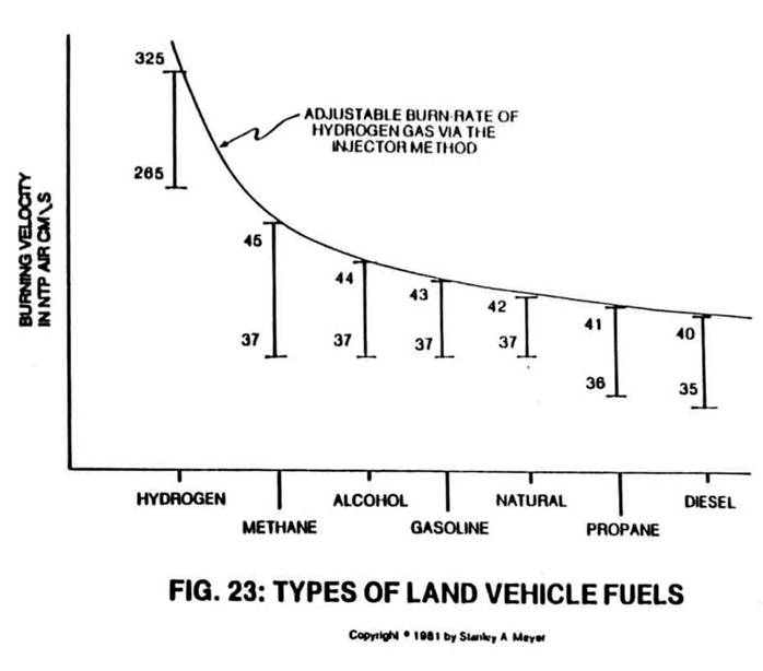](https://stanslegacy.com/uploads/images/gallery/2024-10/agagu4TMrcGFyxIi-image-1729264710483.png) |
The gas flow regulator or **gas valve** (11) can adjust or lower the hydrogen flame temperature below that of burning paper.
This gas modulation process is further used to transport hydrogen gas through conventional gas lines, as shown in Figure 31. [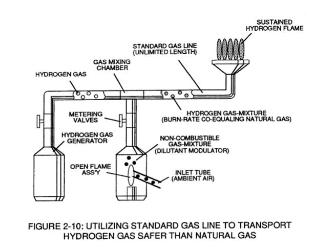](https://stanslegacy.com/uploads/images/gallery/2024-10/2kGCtgvRjd3csfp9-image-1729265366375.png) In another application, the gas modulation technique is also used to run a conventional car engine, as illustrated in Figure 22 as to Figure Graph 23.| [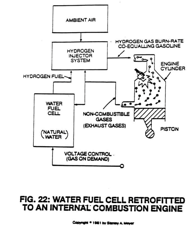](https://stanslegacy.com/uploads/images/gallery/2024-10/Jsrk3KDyzBXETtQy-image-1729264836651.png) | [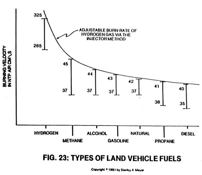](https://stanslegacy.com/uploads/images/gallery/2024-10/dRqIWpgiLbx6o7cZ-image-1729264843227.png) |
| Figure 24SB | Figure 24SC | Figure 24SA |
**Multiple Quenching Circuits** (5a xxx 5n) of Figure 24SB are used to prevent flame-out when the Fuel Cell gases exceed a certain gas velocity.
#### QUENCHING CIRCUIT RELIABILITY: A non-oxidizing material such as alumina (*a type of ceramic material*) is used to form said **quenching disc** (7) to prevent **gas port** (5) enlargement due to chemical interaction and/or heat exposure or both.The **nozzle assembly** (20) itself acts as a heat sink.
#### SUSTAINING AND MAINTAINING A HYDROGEN GAS FLAME: [](https://stanslegacy.com/uploads/images/gallery/2024-10/H40XNTZkh9JH6UrX-image-1729264485208.png)By simply igniting the Fuel Cell **gases** (6) expelling from said **Quenching Nozzle** (20) of Figure 24SB as to Figure 24, a **hydrogen/oxygen flame** (9) of Figure 24SB as to Figure 24 is sustained and maintained regardless of the gas-rate of said Fuel Cell. Flame projection is achievable beyond six inches while flame temperature is variable up to and beyond **5,000 degrees F**.The **modulated gas mixture** (6) near each **quenching circuit** (5) prior to **gas ignition** (9) helps keep **quenching disc** (7) cool to the touch.
#### #### HYDROGEN LEAKAGE:To help prevent hydrogen gas leakage due to quenching circuit flame-out (*Murphy's law of probability*), said quenching circuits (5a xxx 5n) are prearranged in such a way as to allow an **adjacent flame** (9) to re-ignite the expelling fuel gas.
The **overlapping flame pattern** (12a xxx 12n) of Figure 24SB as to Figure 24SA also aids the hydrogen burning process by concentrating flame temperature in a centralized area while said anti-spark back technique (*quenching circuit*) remains intact. #### SECONDARY BURNING ZONE: To ensure total and complete gas combustion during Fuel Cell operations, a **Catalytic Dome** (10) is placed on top of and in space relationship to said **quenching nozzle** (20), as so illustrated in Figure 24SA. The **hemispherical-shaped dome** (13) performs several functions simultaneously: - captures and entraps any and all combustible gases that somehow escape the gas-burning process; - ignites said combustible gases inside said catalytic dome composed of heat-retaining material (like ceramic); - redirects the burning gases back into the sustained hydrogen flame for continuing burning… superheating the gases for **utilization** (14). In actuality, the **hemispherical dome** (10) of Figure 24SA performs as a secondary combustion zone.| [](https://stanslegacy.com/uploads/images/gallery/2024-10/8hpCSBSfX4T9ibph-image-1729265496426.png) | [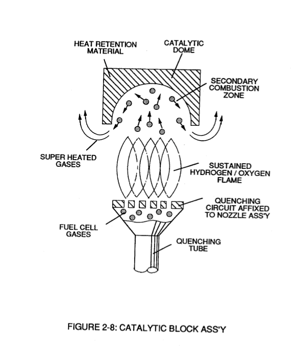](https://stanslegacy.com/uploads/images/gallery/2024-10/yZ24jT2GCuXXp9XD-image-1729265550102.png) |
The superheated gases prevent **Nitrous Oxide** (N2O) formation.
#### WATER PURIFICATION: [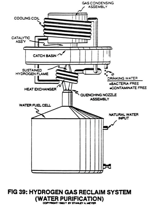](https://stanslegacy.com/uploads/images/gallery/2024-10/yX28FnGLpGx2uNRG-image-1729265037333.png) Water purification is now performed in a three-step operation: contaminates in water remain in the Fuel Cell since voltage is used to dissociate the water molecule; the sustained and maintained hydrogen gas flame kills any and all bacteria that attach themselves to the Fuel Cell gases; cooling the superheated gases moving away from the hydrogen gas flame forms water droplets free of contaminates and bacteria. To accomplish the gas cooling process, a **gas condensing assembly** (40) is attached to the **catalytic block assembly** (10/20), as illustrated in Figure 39. The first stage **heat exchanger** (15) exposed to said **flame temperature** (9) heats a cycling gas that enters into and passes through a **gas expansion chamber** (16). The expanded gas cools another **heat exchanger** (17) exposed to **superheated gases** (14) of Figure 24SA.The resultant temperature gradient performs the water condensing process.
[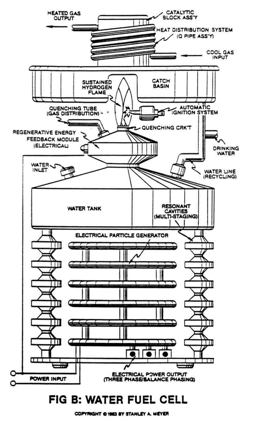](https://stanslegacy.com/uploads/images/gallery/2024-10/tw5sDqY0KoKReDJC-image-1729267754605.png) The **gas condensing assembly** (40) has no moving parts and is self-regulating as to the flame temperature. The collected and stored water inside **catch basin** (18) can be “drained off” for drinking water or re-routed back to the Fuel Cell for hydrogen reuse, as so illustrated in Figure 39 as to Figure B titled “Water Fuel Cell.” During water recycling, the water molecule is re-exposed to **laser energy** (Figure 20FB as to Figure 20K) for **Energy Charging**... duplicating sun exposure. # Magnetic Spin Generator To oscillate a permanently magnetic field through a pickup coil without particle acceleration. # MAGNETIC SPIN GENERATOR **Purpose:**To oscillate a permanently magnetic field through a pickup coil without particle acceleration.
**Circuit Stage:** [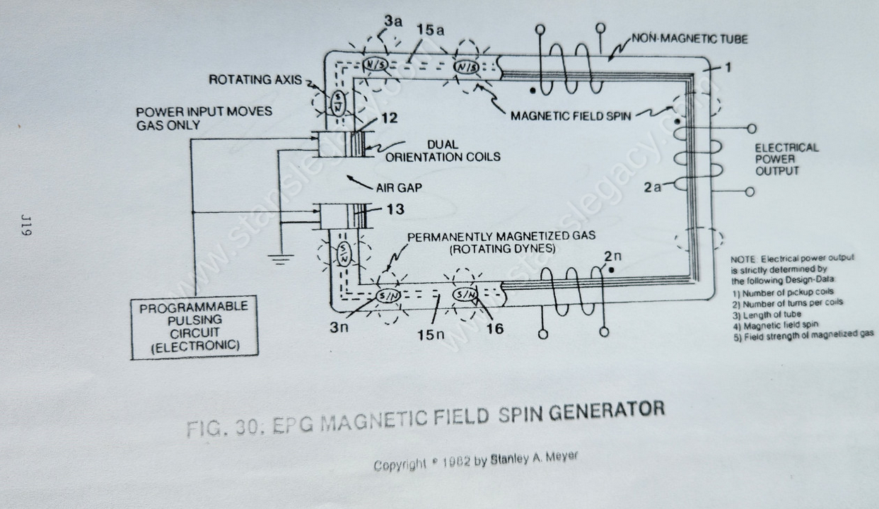](https://stanslegacy.com/uploads/images/gallery/2024-10/HkrFdxXxmCQmMROW-image-1729623833109.png)Placing **dual orientation coils** (12/13) on opposite ends of a **circular non-magnetic tube** (1) supporting a series of **pickup coils** (*2a xxx 2n*)... said hollow tube being filled with permanently magnetized particles of gas... said circular assembly forming an air gap between said orientation coils, as illustrated in Figure 30 as to Figure 30ZC and Figure 30ZD.| [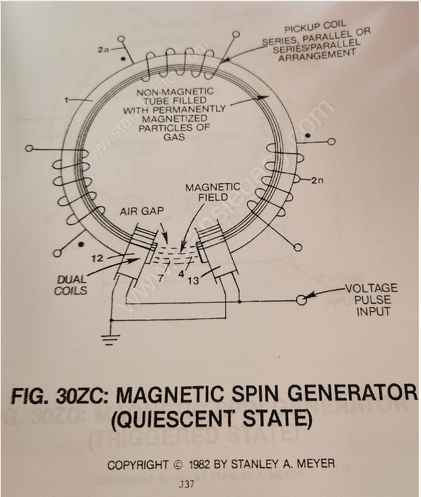](https://stanslegacy.com/uploads/images/gallery/2024-10/c7eoS45eOW683JwQ-image-1729624530181.png) | [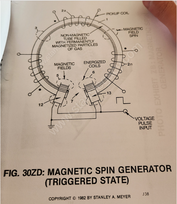](https://stanslegacy.com/uploads/images/gallery/2024-10/pv6T7I2yIhn5dHG5-image-1729623900399.png) |
By simply "switching on" said **variable gate circuit** (EE), a voltage pulse of a given duration is applied to both orientation coils simultaneously... producing **electromagnetic fields** (5/6) of equal magnitude in a North to South relationship to said **air gap** (7) as shown in Figure 30ZD.
--- [](https://stanslegacy.com/uploads/images/gallery/2024-10/pv6T7I2yIhn5dHG5-image-1729623900399.png)Once said **orientation coils** (12/13) become "electrically energized" and form **electromagnetic fields** (5/6), the **electromagnetic field** (7) across said **air gap** (4) of Figure 30ZC is terminated since said particle alignment of said **gas** (16) is "rotated" or "flipped" 90 degrees from point of **Quiescent**... forming **electromagnetic field** (3) of Figure 30 along the longitudinal axis of said **tubular structure** (1)... allowing said **electromagnetic field** (3) to expand, to pass through and beyond **pickup coils** (2a xxx 2n), as illustrated in Figure 30ZD. Once said **orientation coils** (12/13) become de-energized (switching off applied electrical power), said permanently **magnetized particles** (16a xxx 16n) now "rotate" or "flip" another 90 degrees to reform electromagnetic field (4) once again while simultaneously "switching on" said **electromagnetic field** (3). ---The collapsing **electromagnetic field** (3) passes through **pickup coils** (2a xxx 2n) forming a bipolar voltage pulse across said pickup coils.
##### MAGNETIC FIELD INTERACTION: [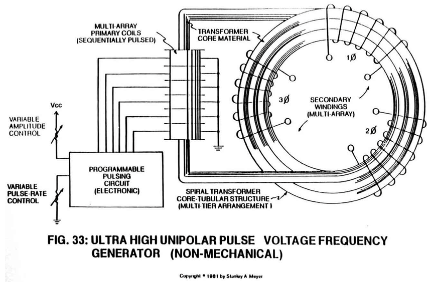](https://stanslegacy.com/uploads/images/gallery/2024-10/iA8DbdlGxg2gL0pE-image-1729624457766.png)To increase electrical power output further, simply **spiral-wrap** (1a xxx 1n) **non-magnetic tube** (1) through said **pickup coils-array** (2a xxx 2n), as illustrated in Figure 33. The spiral-wrap configuration increases the number of **magnetic flux lines** (*magnetic field*) surrounding the tubular leg, "cutting" or "passing" through said **coil-array** (2a xxx 2n). ##### POWER INPUT vs. POWER OUTPUT: Permanently magnetized particles of gas prevent electromagnetic coupling between said **orientation coils** (12/13) and said **pickup coils** (2a xxx 2n).Power input rotates or spins said particles of gas to produce an **oscillating magnetic field** (3).
#### ELECTRICAL POWER CONVERTER: The **Magnetic Spin Generator** becomes an A.C. electrical generator when the pickup coil-array is series-wrapped in a Right-Hand to a Left-Hand relationship. D.C. electrical output occurs when the coil-array is wrapped in the same direction. Orientation coils can be either pulsed by a D.C. and/or A.C. electrical power input. Electrical power conversion D.C. to D.C., D.C. to A.C., and/or A.C. to A.C. are obtainable. # Steam Resonator Purpose: To produce superheated steam by way of pulsating voltage fields on opposite sides of a water molecule while restricting amp flow. # Steam Resonator ##### **Steam Resonant Cavity****Purpose**: To produce superheated steam by way of pulsating voltage fields on opposite sides of a water molecule while restricting amp flow.
##### **[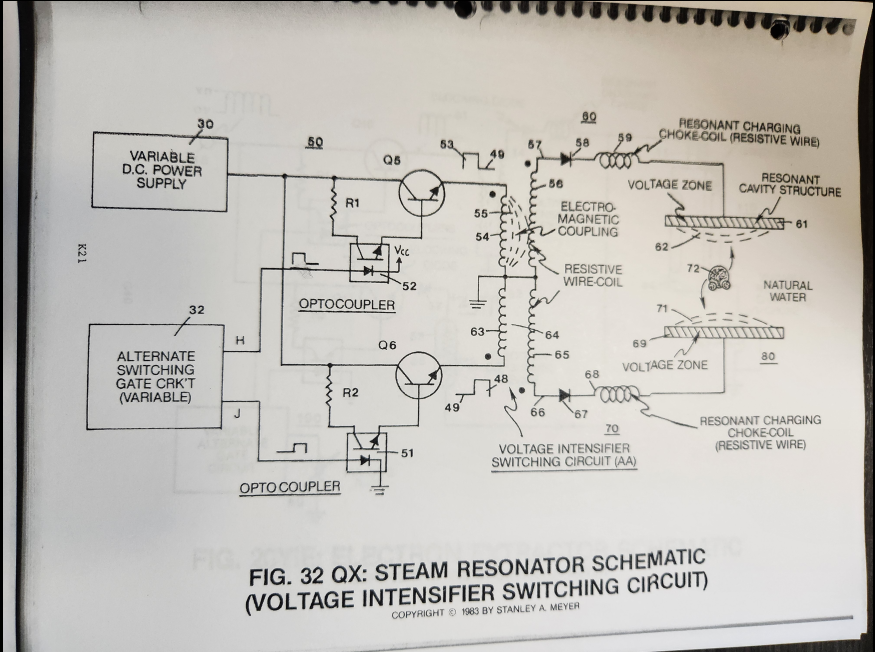](https://stanslegacy.com/uploads/images/gallery/2024-10/I4WiNftatt5Oyo1e-image-1729552716579.png)Circuit Stage**: Integrating **alternate pulsing circuit** (Q5) as to (Q6) to said **voltage intensifier switching circuit** (AA) arranged in a dual polarity configuration, as illustrated in Figure 32QX titled Steam Resonator Schematic. ##### **SEQUENTIAL GATE CIRCUIT** As shown in Figure 32QX, **variable gate circuit** (32) is a two-state switch device which is directly linked to both **optocoupler** (51) and **optocoupler** (52). As (H) nears ground or low state (zero volts), **optocoupler** (52) is triggered "on," allowing **power switch** (Q5) to form **unipolar voltage pulse** (53). Once said **gate circuit** (32) changes voltage state (low to high or vice versa), **trigger pulse** (J) turns on **optocoupler** (51) that "switches" on **power switch** (Q6) to form another **unipolar voltage pulse** (48). **Triggered pulse** (H) is now terminated, switching off said **voltage pulse** (53).Repeating said **alternate gate switching** (H) as to (J) applies an alternate duty pulse of positive polarity to said **Voltage Intensifier Switching Circuit** (AA), as shown in Figure 32QX.
**Gate circuit** (32) varies or regulates said **duty pulse** (53/48) up to one megahertz or more.
--- ##### **[](https://stanslegacy.com/uploads/images/gallery/2024-10/I4WiNftatt5Oyo1e-image-1729552716579.png)Voltage Intensifier Switching Circuit** As **duty pulse** (53) is formed across **primary coil** (54), an **electromagnetic field** (55) is produced and coupled with pickup coil (56)...forming a **voltage potential** (57) across said **pickup coil** (56). Since said **pickup coil** (56) is composed of resistive wire, amp flow is being restricted within the **voltage intensifier circuit** (60) as previously described in WFC Tech Brief Section 4 titled **Voltage Attenuation Circuit Design Specs**. ---The produced **voltage potential** (57) now gates "ON" **unidirectional diode** (58)...allowing said **voltage potential** (57) to pass to, through, and beyond in-line charging **Choke Coil** (59) to **Excitor Plate** (61)...forming **positive voltage field** (62).
Amp flow is further reduced since said inline **choke coil** (59) is also composed of resistive wire. **Voltage field** (62) ceases to exist when said **duty pulse** (53) is terminated or "switched-off." Repeating said **duty pulse** (53) sets up a **pulsating voltage field** (62) of positive polarity across said **Excitor Plate** (61) while **circuit** (60) restricts amp flow to a minimum value. **Excitor Plate** (61) is made of Stainless Steel T304 material to prevent chemical interaction or material oxidation with natural water. **Blocking diode** (58) prevents electrical shorting from occurring across said **pickup coil** (56) during said pulsing operations. **Gated pulse** (H) can be proportionally changed via **gate circuit** (32) to "concentrate" or "expand" said **applied voltage** (57) to said **voltage zone** (61) during pulsing operations.As **on-time** (53) increases, **off-time** (49) proportionally decreases. Pulse adjustment is reversible.
**Voltage Intensifier Circuit** (70) is an exact duplicate of **interfacing circuit** (60) and performs in like manner...except **duty pulse** (48) is applied to a second **Excitor Plate** (69) exposed to the opposite side of the same water molecule.
Together **Voltage Intensifier Circuits** (60) and (70) form **Voltage Intensifier Switching Circuit** (AA) of Figure 32QX. **Excitor Plate** (61) and **Excitor Plate** (69) form **Steam Resonant Cavity** (80) of Figure 32. **Steam Resonant Cavity** (80) can take on different design configurations to meet a predetermined steam-yield. --- ##### **Voltage Field Oscillation** **Dual pulsing circuit** (50) linked to said **Voltage Intensifier Switching Circuit** (AA) simply switches or alternates a unipolar positive voltage pulse from one **Excitor Plate** (61) to another **Excitor Plate** (69) in a sequential manner to produce superheated steam by way of voltage deflection of the water molecule.To increase the rate of steam production, simply increase the formation-rate of said **voltage fields** (62/71) across said **voltage zones** (61/69).
--- ##### **[](https://stanslegacy.com/uploads/images/gallery/2024-10/sQ3Cf8cvHFCc5kR9-image-1729553367681.png)Electrical Charging of the Water Molecule** Since the water molecule is naturally held together by an electrical field of opposite polarity, the hydrogen atoms take on a positive electrical charge relative to the negative charge oxygen atom, as illustrated in Figure 2 of said WFC Tech Brief. Said electrical fields of opposite polarity surround said water molecule atoms. The sum total of the positive electrical charges equals the sum total of the negative electrical charge between said unlike atoms... providing electrical equilibrium of the water molecule. --- **Voltage Deflection of the Water Molecule** By simply applying a positive **voltage potential** (62) across said **Excitor Plate** (61) for a moment of time, the **water molecule** (72) of Figure (2) as to Figure (32QX) is now deflected or moved toward said **voltage zone** (61) due to opposite electrical attraction force between said negative charged oxygen atom of said water molecule and said **positive electrical voltage zone** (62). Switching "OFF" said **electrical voltage field** (62) while switching "ON" said **positive** **electrical voltage field** (71) now causes said **water molecule** (72) to "deflect or move" in opposite direction towards said **voltage zone** (69)...colliding with other water molecules undergoing the same voltage deflection process...generating heat due to particle impact, as illustrated in Figure 32.| [](https://stanslegacy.com/uploads/images/gallery/2024-10/sQ3Cf8cvHFCc5kR9-image-1729553367681.png) | [](https://stanslegacy.com/uploads/images/gallery/2024-10/Aza3UM3GjwP1vhke-image-1729553800227.png) |
To increase steam-yield still further, simply increase the voltage amplitude of said **D.C. power supply** (30) of Figure 32QX.
---**Caution**: DO NOT SIMULTANEOUSLY APPLY AN OPPOSITE ELECTRICAL VOLTAGE FIELD ACROSS SAID WATER MOLECULE UNLESS YOU WANT TO PRODUCE HYDROGEN GAS ON DEMAND. THIS PROCESS IS CALLED "THE ELECTRICAL POLARIZATION PROCESS."
# Electrical Particle Generator Objective: To overcome the opposing magnetic field problems associated with rotary electrical generators. # ELECTRICAL PARTICLE GENERATOR **Objective**: To overcome the opposing magnetic field problems associated with rotary electrical generators. ##### **PRE-HISTORY TO DEVELOPMENT**: To satisfy Maxwell and Faraday Laws of inductance to produce electrical energy, a magnetic field must pass through a conductor or a conductor must pass or move through a magnetic field. In each case the results are the same. This now establishes the basic operational parameter related to rotary electrical generators.To design said **rotary electrical generator**, the following design parameters must be utilized to reach maximum operational performance:
**POWER FACTOR OF DESIGN**: 1. Strength of Magnetic Field (number of magnetic flux lines) 2. Velocity or speed at which a magnetic field passes through a conductive wire 3. Number of loops or turns per wire-coil 4. Number of pickup coils 5. Energy input to produce and maintain said rotating electromagnetic field (applied electrical energy) 6. Energy input to rotate or move said electromagnetic field (applied mechanical energy) **Point-of-Observation**: A magnetic flux line does not show signs of deterioration when passing through an electrical conductive wire. **Observations-Test**: An electromagnetic field emanating from a permanent magnet rotating inside an electrical wire-coil produces electrical energy. Said permanent magnet requires no energy input to maintain said magnetic field, see [Thomas Edison generators](https://edison.rutgers.edu/life-of-edison/inventions?catid=91&id=530&view=article). **Typical Rotary Electrical Generator**: Car Alternator **Operational Characteristics**: **maximum duty loading** 1. Apply 120 watts (12 volts x 10 amps) of electrical power to armature winding to produce said electromagnetic field. 2. Apply 5,222 watts (7 hp x 746 watts) to "start" and "rotate" said armature to move said electromagnetic field through said pickup coils during maximum duty loading. 3. Three rotor pickup coils (300 turns per coil; 3 coils per stator ring array) produces 720 watts (12 volts x 60 amps) output during said maximum duty loading. ##### **Second Point-of-Observation**: The **opposing magnetic fields** (a xxx an) (*opposite polarity attraction*) between said armature and said stator ring consumes tremendous amounts of mechanical energy during deformation of said **attraction fields** (a), see Figure 25ZA.Said **opposing magnetic fields** (a) resist said armature rotation.
##### **Observation Test**: Once said **electromagnetic circuit** is formed (a), said **opposite polarity attraction** (*north to south magnetic pole interaction*) tries to prevent armature rotation. *A **stationary armature** (electrically* energized) cannot rotate without exerting mechanical torque (*rotational force*) energy to said armature. Said mechanical energy input is directly proportional to said **magnetic field strength** (a). Increasing said **electromagnetic field strength** (a) requires an increase in mechanical energy input.Counter EMF electrical field is not formed around said pickup coils since said armature is stationary during static testing.
**Scientific Fact**: > Said Maxwell/Faraday Laws of inductance require that a magnetic field must pass through said pickup coil to generate a counter EMF electromagnetic field, see Exhibit AZ, McGraw-Hill Encyclopedia of Science and Technology, Vol. 6, page 144. **Point of Discovery**: Elimination of said "Air Gap" attraction problem can help reduce energy input requirements to produce electricity. --- ##### **The Birth of New Technology: Electrical Particle Generator (EPG)** **Design Objective**: To move and attenuate a permanent magnetic field through a pickup coil array without said "Air Gap." --- #### **Electrical Particle Generator: Assembly & Operability** ##### **A) Magnetic Pathway: Closed loop system** Take a **non-magnetic tube** (*material that will not become permanently magnetized when exposed to a magnetic field and having the capability of distorting said magnetic field through said tubular material without signal distortion… such as aluminum, brass, glass, and/or plastics*) and form a **closed loop pathway** (*without open ends*), as illustrated in (1) of Figure 26 through Figure 30.| [](https://stanslegacy.com/uploads/images/gallery/2024-10/tYSeCbe9BF34ik0X-image-1729698664899.png) | [](https://stanslegacy.com/uploads/images/gallery/2024-10/vPmH1J09GzeI7YH3-image-1729568840461.png) |
| [](https://stanslegacy.com/uploads/images/gallery/2024-10/jV5842wLneom6bjK-image-1729568848276.png) | [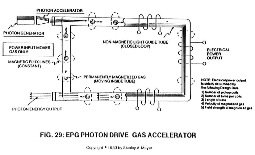](https://stanslegacy.com/uploads/images/gallery/2024-10/MfYuwau4z4tLpfGE-image-1729568854073.png) |
Wrap a **wire-coil** (2) and/or **coil-array** (2a xxx 2n) around one end of said **non-magnetic tube** (1) to comply with Maxwell/Faraday Laws of Inductance.
[](https://stanslegacy.com/uploads/images/gallery/2024-10/iA8DbdlGxg2gL0pE-image-1729624457766.png)Said **pickup coil** (2) is placed around said **spiral pathway** (8) of Figure 33 to form a **coil-array** (2a xxx 2n). ##### **C) Particle Accelerator Assembly: Purpose & Placement** Insert into and affixed a **Particle Accelerator Assembly** (10) to said **closed loop tube** (1) as to (8), locating said Particle Accelerator Assembly on opposite end of **tube** (1) away from said **pickup windings** (2 xxx 2n), as shown in Figure 26. --- [](https://stanslegacy.com/uploads/images/gallery/2024-10/tYSeCbe9BF34ik0X-image-1729698664899.png)Said **Particle Accelerator Assembly** (10) causes and propels a **permanent magnetic fluid-medium** (3 of Figure 26) (*liquid slurry or gases*) to move toward, through, and beyond said **pickup coils** (2) for recycling, as illustrated in Figure 26.Said **Particle** **Accelerator Assembly** (10) can take on different design configurations to utilize different energy inputs to overcome different climatic and operational conditions.
--- A **Mechanical Accelerator Drive Assembly** (20 of Figure 27) utilizes a **non-magnetic turbine wheel** (21) to physically move said **magnetic fluid-medium** (3) inside said **tubular pathway** (1).| [](https://stanslegacy.com/uploads/images/gallery/2024-10/vPmH1J09GzeI7YH3-image-1729568840461.png) | [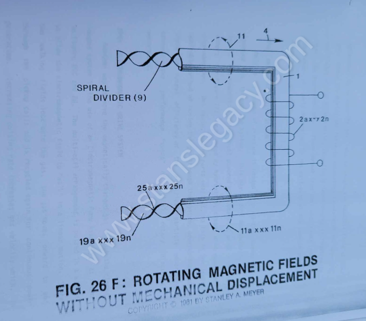](https://stanslegacy.com/uploads/images/gallery/2024-10/0WPinvE1yJJT8VVJ-image-1729699457603.png) |
| [](https://stanslegacy.com/uploads/images/gallery/2024-10/ECD8ihbWga3Tseii-image-1729713795923.png) | [](https://stanslegacy.com/uploads/images/gallery/2024-10/iA8DbdlGxg2gL0pE-image-1729624457766.png) |
Said **mechanical drive system** (20) and/or **Electromagnetic Pump Assembly** (30) can be used separately, joined together, or periodically spaced around said **tubular structure** (1) as to (8).
--- ##### **D) Energy Input: Mechanical to Electrical Interfacing** **Power Train linkage** (22) to said **non-magnetic turbine wheel** (21 of Figure 27 can take different forms:AC/DC Electric Motor powered by solar or conventional electrical power; Hydraulics; Steam Power; Wind Power; Internal combustion engine, and/or manpower.
**Electromagnetic Pump Assembly** (30 of Figure 28 as to Figure 33) is energized by a variable AC electrical **power source** (34).| [](https://stanslegacy.com/uploads/images/gallery/2024-10/jV5842wLneom6bjK-image-1729568848276.png) | [](https://stanslegacy.com/uploads/images/gallery/2024-10/iA8DbdlGxg2gL0pE-image-1729624457766.png) |
| [](https://stanslegacy.com/uploads/images/gallery/2024-10/tYSeCbe9BF34ik0X-image-1729698664899.png) | [](https://stanslegacy.com/uploads/images/gallery/2024-10/vPmH1J09GzeI7YH3-image-1729568840461.png) |
| [](https://stanslegacy.com/uploads/images/gallery/2024-10/MfYuwau4z4tLpfGE-image-1729568854073.png) | [](https://stanslegacy.com/uploads/images/gallery/2024-10/HkrFdxXxmCQmMROW-image-1729623833109.png) |
Said **permanently magnetized material** (3) can either be in a liquid slurry and/or gas form.
Said liquid slurry is composed of **micro-size permanently magnetized particles** suspended in a fluid-medium such as **liquid Teflon** or light-oil, forming a homogeneous liquid-mass.
Said permanently magnetized gas is composed of atom-size permanently magnetized particles suspended onto an inert carrier gas such as nitrogen argon, forming a homogeneous gas-mass.
Both homogeneous masses **can be doped** with different permanently magnetized atoms to encourage electromagnetic field enhancement.
**Scientific Fact**: > The smallest part of a permanent magnet is its atomic structure. ##### **F) Magnetic Field Formation: An Electronic Process** Once said **tubular pathway** (1) as to (8) is completely filled with said **permanently magnetized material** (3), said **pickup coil-array** (2a xxx 2n) is electrically energized to produce an electromagnetic field that completely surrounds said **tubular pathway** (8) of Figure 33, exposing said **magnetic material** (3) to said electromagnetic field... causing said **material** (3) to become permanently magnetized...forming a **longitudinal field** (4) of Figure 26 emitting from said **tubular pathway** (1). Said **longitudinal field** (4) remains after said **coil-array** (2a xxx 2n) is de-energized.| [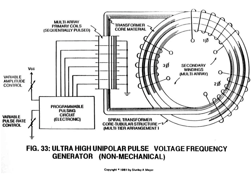](https://stanslegacy.com/uploads/images/gallery/2024-10/jQTQVT4yguejziI3-image-1729568489425.png) | [](https://stanslegacy.com/uploads/images/gallery/2024-10/tYSeCbe9BF34ik0X-image-1729698664899.png) |
No other energy is needed to maintain said **magnetic field** (4).
> **Electronic Fact**: At this point, above said magnetizing process duplicates the same function as a **Toroidal Pulsing Core** in electronic circuit applications. Except said Toroidal core material becomes demagnetized after electrical power is removed. ##### **G) Magnetic Fields Movement: Linear Spin** **Longitudinal movement** (*moving permanently magnetized fluid-medium inside said tubular pathway*) of said **magnetic field** (4 of Figure 26) is simply accomplished when said **Electro/mechanical Pump Assembly** (20) of Figure 27 and/or **Electromagnetic Pump Assembly** (30) of Figure 28 is energized for operability.| [](https://stanslegacy.com/uploads/images/gallery/2024-10/ELdUfU5cNL4H9FcO-image-1729568832482.png) | [](https://stanslegacy.com/uploads/images/gallery/2024-10/vPmH1J09GzeI7YH3-image-1729568840461.png) | [](https://stanslegacy.com/uploads/images/gallery/2024-10/jV5842wLneom6bjK-image-1729568848276.png) |
By attenuating or varying power input to said **power drive systems** (20 and/or 30) likewise varies the recycling speed or velocity of said **magnetic field** (4) moving toward, through, and beyond said **pickup coil-array** (2a xxx 2n)... moving onward to and through said **Power Drive Assembly** (20 and/or 30) once again for continued field recycling.
| [](https://stanslegacy.com/uploads/images/gallery/2024-10/ELdUfU5cNL4H9FcO-image-1729568832482.png) | [](https://stanslegacy.com/uploads/images/gallery/2024-10/0WPinvE1yJJT8VVJ-image-1729699457603.png) |
| [](https://stanslegacy.com/uploads/images/gallery/2024-10/jV5842wLneom6bjK-image-1729568848276.png) | [](https://stanslegacy.com/uploads/images/gallery/2024-10/jQTQVT4yguejziI3-image-1729568489425.png) |
The linear-spin movement of said **magnetic field** (4/11) now duplicates the magnetic field spin of Figure 26ZA without the opposing magnetic field problem (*caused by said "Air Gap"*) associated with standard rotary electrical generators, see **"Pre-History to Development"** again.
Said **Rotary Electrical Generator** (Figure 26ZA) simply moved the armature field in one direction;whereas, the EPG System now moves said **magnetic field** (4/11) in two directions simultaneously:
(4) **linear direction**, (11) **axial** or **spin rotation**. --- ##### **H) Magnetic Field Deflection: Oscillating a permanent magnetic field** To pulsate or vary said **rotational field** (11) moving in a **linear direction** (4), **Dual-Orientational coils** (12/13 of Figure 27) are now inserted into said tubular pathway on opposite side of **Electromechanical Drive System** (20), away from said **pickup coil-array** (2a xxx 2n), as illustrated in Figure (27) as to Figure 30.| [](https://stanslegacy.com/uploads/images/gallery/2024-10/vPmH1J09GzeI7YH3-image-1729568840461.png) | [](https://stanslegacy.com/uploads/images/gallery/2024-10/HkrFdxXxmCQmMROW-image-1729623833109.png) |
The **dual-pulsing coils** (12/13) perform a sequential function:
[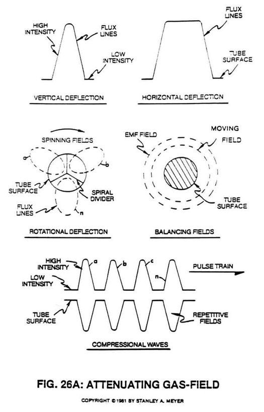](https://stanslegacy.com/uploads/images/gallery/2024-10/EYJwp3N9OUIkVXaP-image-1729730454152.png) First, when electrically energized, said **dual-coils** (12/13) stabilize said **magnetic field** (4/11) since said **turbine wheel** (21 of assembly 20) disrupts the **electromagnetic field alignment** (15a xxx 15n) (*electromagnetic attraction force*) between said **permanently magnetized particles** (3a xxx 3n) moving inside **non-magnetic tubular pathway** (1 as to 8), see Figure 27 as to Figure 30. Secondly, said **moving field** (4/11) is terminated when said **dual-coil assembly** (12/13) is de-energized... allowing said particles (15a xxx 15n) to go into a state of reformation of said magnetic field sequence. Re-energizing said **coils** (12/13) causes said **particles** (3a xxx 3n) to go into alignment once again... reforming **magnetic field** (4/11). Pulsing said **Orientation-coils** (12/13) quickly causes a **vertical deflection** (17a xxx 17n of Figure 26A) of said **magnetic field** (4/11). Pulsing said Orientation-coils slowly causes a **horizontal deflection** (18a xxx 18n of Figure 26A) of said **magnetic field** (4/11).In both cases, said **reforming** **magnetic wave-forms** (17a xxx 17n and/or 18a xxx 18n) are oscillating inside said **coil-array** (2a xxx 2n)... producing electrical energy.
---**Pulse-frequency electrical output** (23 of Figure 30 as to Figure 27) is strictly determined by the pulse-rate of said **orientation coils** (12/13).
| [](https://stanslegacy.com/uploads/images/gallery/2024-10/HkrFdxXxmCQmMROW-image-1729623833109.png) | [](https://stanslegacy.com/uploads/images/gallery/2024-10/vPmH1J09GzeI7YH3-image-1729568840461.png) |
| [](https://stanslegacy.com/uploads/images/gallery/2024-10/iA8DbdlGxg2gL0pE-image-1729624457766.png) | [](https://stanslegacy.com/uploads/images/gallery/2024-10/yHKotVDKYIEID5GY-image-1729131224050.png) |
**Transformer interaction** (*magnetic field coupling*) between said **Orientation Coils** (12/13) and said **pickup coils** (2a xxx 2n) can "NOT" occur since said **particles** (3a xxx 3n) are permanently magnetized.
The magnetic pulsing process simply spins the dyne-axis of **said particles** (3a xxx 3n) to oscillate and attenuate a **permanent** **magnetic field** (4/11 as to 17/18), as illustrated in Figure 30 as to Figure 26 through Figure 33.| [](https://stanslegacy.com/uploads/images/gallery/2024-10/HkrFdxXxmCQmMROW-image-1729623833109.png) | [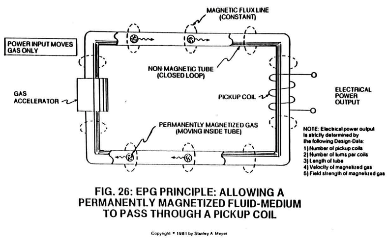](https://stanslegacy.com/uploads/images/gallery/2024-10/YITRFOekWD3T86QW-image-1729713849522.png) |
The **multi-channel spiral divider** (19a xxx 19n) is composed of any type of material (*such as electrical steel M27*) that will "NOT" become permanently magnetized (*when exposed to said moving **magnetic field** (4)*) when "shunting" said **magnetic field** (11a xxx 11n), as shown in Figure 26A sub-titled "Rotational Deflection."
| [](https://stanslegacy.com/uploads/images/gallery/2024-10/oU5VWJKo3ggJE0h3-image-1729730448270.png) | [](https://stanslegacy.com/uploads/images/gallery/2024-10/0WPinvE1yJJT8VVJ-image-1729699457603.png) |
If more **longitudinal magnetic fields** (19a xxx 19n) are required... simply increase the number of **pathway channels** (19).
[](https://stanslegacy.com/uploads/images/gallery/2024-10/iA8DbdlGxg2gL0pE-image-1729624457766.png)To increase said **magnetic flux lines** (11a xxx 11n) still further, said **pathway** (1) is now spiraled (8 of Figure 33) (*in spaced relationship to each other*) inside said pickup **coil-array** (2a xxx 2n), as illustrated in Figure 33 as to cross-sectional drawing titled "Multi-tubular array"of Figure 28A.The greater number of spiral-turns (8a xxx 8n) the greater number of right-hand lines transverses said pickup coil array (2a xxx 2n) during pulse-form stage.
---The number of "shunting" magnetic fields (11a xxx 11n) times (x) the number of spiral pathways (8a xxx 8n) determine the magnetic field strength of said EPG system of Figure 26C.
| [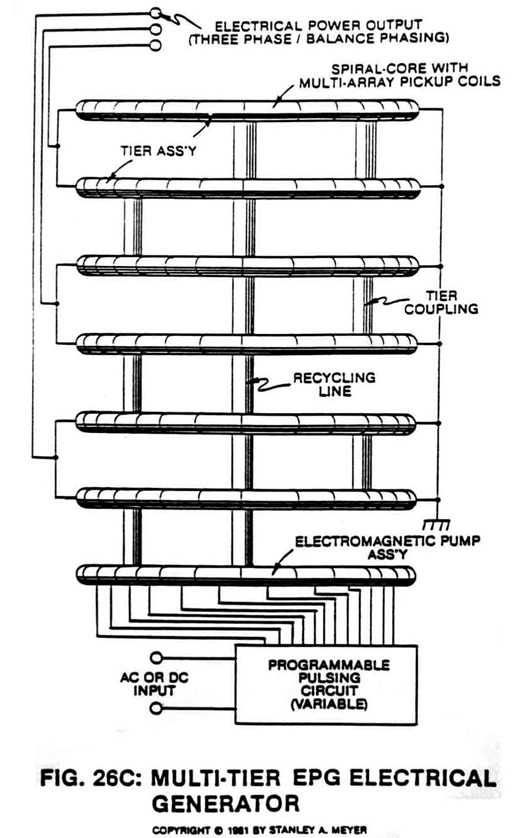](https://stanslegacy.com/uploads/images/gallery/2024-10/7Z9VbD5lJjjzV6cR-image-1729730668576.png) | [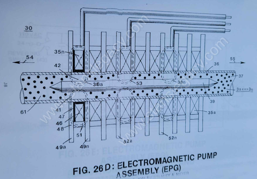](https://stanslegacy.com/uploads/images/gallery/2024-10/USfOHAa5qEsVeEk4-image-1729734343970.png) |
To speed up said **magnetic field spin** (11a xxx 11n), simply increase the velocity of said **magnetized fluid-medium** (3a xxx 3n) traveling through said **pathways** (19a xxx 19n)... or vice versa.
By increasing the **number of turns** (*twist configurations*) (25a xxx 25n of Figure 26F) per linear measurement of said **spiral-divider cluster** (19a xxx 19n) also increases said **magnetic spin** (4/11) still further once said **fluid-velocity** (4) is reached. In both cases, said **magnetic field spin** (11a xxx 11n) is not subject to the rotational/mechanical limitation of said **Rotary Electrical Generator** of Figure 26ZA.| [](https://stanslegacy.com/uploads/images/gallery/2024-10/0WPinvE1yJJT8VVJ-image-1729699457603.png) | [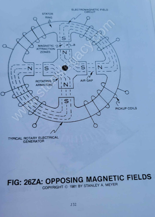](https://stanslegacy.com/uploads/images/gallery/2024-10/Dw9PvTJ5eDTFGI7g-image-1729699080588.png) |
**--- Unidirectional pulsing** (27/28) occurs since the **Linear-Spin movement** (11) of said **pulsating magnetic field** (17/18) is moving in one direction.
**--- Balance-Phasing** (*equal magnetic field strength between said pickup coil-array 2a xxx 2n*) is automatic since **particle velocity** (4) remains constant while passing through said **close-loop tubular pathway** (1).
> Series to parallel hookup of said **coils** (2a xxx 2n) determines amp draw as to applied voltage. Power Output = Amps x Voltage. **[](https://stanslegacy.com/uploads/images/gallery/2024-10/jV5842wLneom6bjK-image-1729568848276.png)Pickup coil-array phasing** (26a xxx 26n) also occurs when splitting said **tubular pathway** (1) into **parallel legs** (1a xxx 1n), as shown in Figure 28. **Electrical Power Output: Power Factor of Design** Electrical power output of said **Electrical Particle Generator** (EPG) is determined as subscribed below: 1. The velocity or movement of said **permanent magnetic fluid-medium** (3a) inside **tubular pathway** (1) (*magnetic field movement per second in a linear direction*). 2. The number of **pathway-channels** (19a xxx 19n) per **spiral-divider** (9) forming **magnetic circuits** (11a xxx 11n) per **spiral-divider** (9) spinning in a linear direction per 360 degrees (*the number of magnetic fields formed per second*). 3. The number of turns or twist per (25a xxx 25n) unit length of said **spiral divider** (9) inserted into said **tubular pathway** (1), the number of magnetic fields spins of said **multi-fields** (11a xxx 11n) per second of linear-travel. 4. The magnetic field strength (*number of magnetic flux-lines per unit volume of said magnetic **fluid-medium** (3)*). 5. The number of **tubular-legs** (8a xxx 8n) spiraled inside said pickup **coil-array** (2a xxx 2n). The number of **multi-rotational fields** (11a xxx 11n) formed per turns of **tubular legs** (8a xxx 8n). 6. The pulse-rate frequency of said **orientational coils** (12/13) to spin or rotate said dyne-axis of said **magnetic fluid-medium** (3) to oscillate said **permanent magnetic field** (11a xxx 11n). 7. The number of turns per coil of wire. 8. The number of coils per **coil-array** (2a xxx 2n). --- ##### **L) Power Input: To Start & Maintain EPG Operations** Power input is required to move said **magnetic fluid-medium** (3) through said **closed-loop tubular pathway** (1). Power input is also required to rotate said dyne-axis of said magnetized **fluid-medium** (3).The basic purpose of said power input is to physically attenuate said **permanently magnetized fluid-medium** (3)... which in turn oscillates a **permanent magnetic field** (4/11).
##### **M) EMF Counter Measures: Minimizing Power Input** To help minimize opposition to the movement of said magnetic fluid-medium during power on-stage, said pickup **coil array** (2a xxx 2n) of Figure 33 as to Figure 26F is placed and aligned end-to-end around said **pathway** (8a xxx 8n) for the purpose of coupling and forming a single and **continuous magnetic field** (31) or any type of electromagnetic field emanating from said **pickup coil-array** (*during duty loading*) is wrapped and positioned around said **pickup coil-array** (2a xxx 2n)... forming a **concentric magnetic ring** (31) around said **pickup coil-array** (12/13) as illustrated in Figure 26A sub-titled "Balancing Fields." Said **oscillating magnetic ring** (31) also forms a **concentric magnetic ring** (29) inside and below said **tubular pathway** (1). The space **formed** (32) between said **magnetic fields** (29 and 31) allows said magnetic lines to cross one another... reducing the opposition to the magnetic field movement.In other words, passing the force-lines between each other magnetic field without said fields opposing each other.
> **Maxwell/Faraday Laws** demonstrate that a space is formed between magnetic flux-lines... this is also known as the standing magnetic wave theory. By synchronizing said **magnetic compression wave** (oscillating magnetic field 17/18) with said **EMF field** (31) termination, EMF field opposition is held to a minimum. See Figure 26A subtitled "Compression Waves." When **EMF field** (31) is formed, said **pulsating magnetic field** (29) forming **concentric ring** (29) is turned off (switched off).| [](https://stanslegacy.com/uploads/images/gallery/2024-10/YITRFOekWD3T86QW-image-1729713849522.png) | [](https://stanslegacy.com/uploads/images/gallery/2024-10/EYJwp3N9OUIkVXaP-image-1729730454152.png) |
| [](https://stanslegacy.com/uploads/images/gallery/2024-10/0WPinvE1yJJT8VVJ-image-1729699457603.png) | [](https://stanslegacy.com/uploads/images/gallery/2024-10/7Z9VbD5lJjjzV6cR-image-1729730668576.png) |
**The Electromechanical actuator** (*Electromagnetic Pump Assembly (30)*) attached to said **tubular pathway** (1) operates as a direct-drive principle of a linear induction motor.
[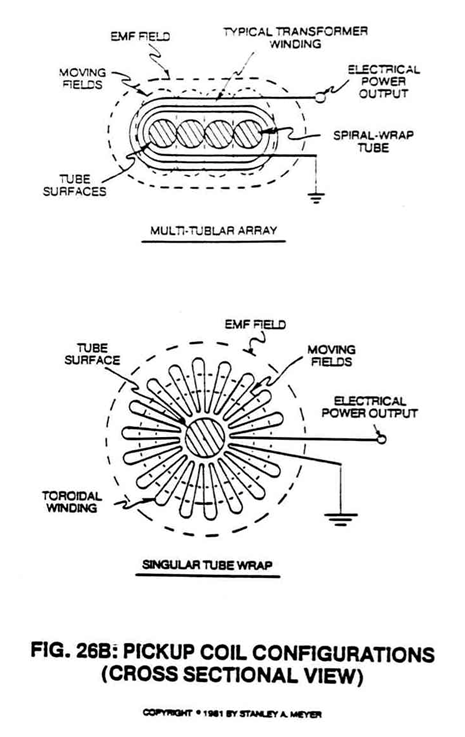](https://stanslegacy.com/uploads/images/gallery/2024-10/rYPtRRwOcSG20Hyf-image-1729730524941.png)The **coil-array** (35a xxx 35n) of Figure 26C, besides being the stator, the **magnetic field medium** (3a xxx 3n) is displaced along a movable/non-movable electromagnetic tubular surface (*of Figure 26C) which, in reference to Figure 28*) acts as a bearing surface (since **said surface** (35a xxx 35n) is fixed).| [](https://stanslegacy.com/uploads/images/gallery/2024-10/EYJwp3N9OUIkVXaP-image-1729730454152.png) | [](https://stanslegacy.com/uploads/images/gallery/2024-10/6XHKhvyo7Tgyu86I-image-1729730651882.png) |
| [](https://stanslegacy.com/uploads/images/gallery/2024-10/tYSeCbe9BF34ik0X-image-1729698664899.png) | [](https://stanslegacy.com/uploads/images/gallery/2024-10/iA8DbdlGxg2gL0pE-image-1729624457766.png) |
The **magnetic pump assembly** (30) may operate on three-phase alternating current or with a **capacitor** (33) (*see schematic drawing Figure 26E as to Figure 26C*) on single-phase alternating current.
| [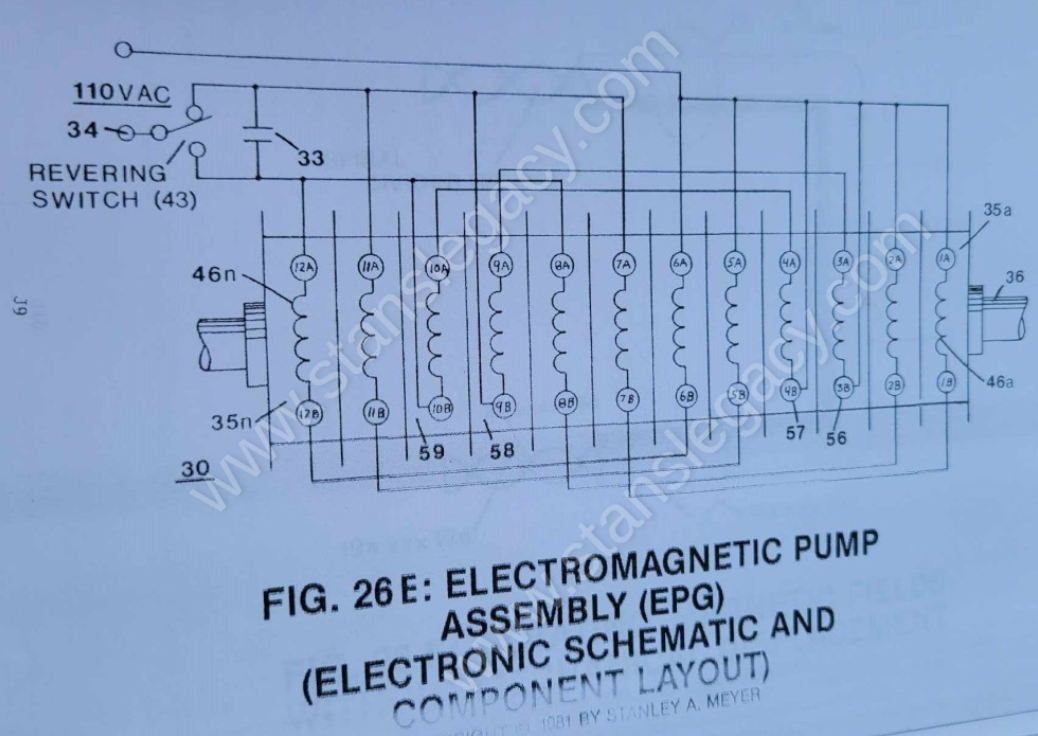](https://stanslegacy.com/uploads/images/gallery/2024-10/M7inajv1n4YpLydq-image-1729712616828.png) | [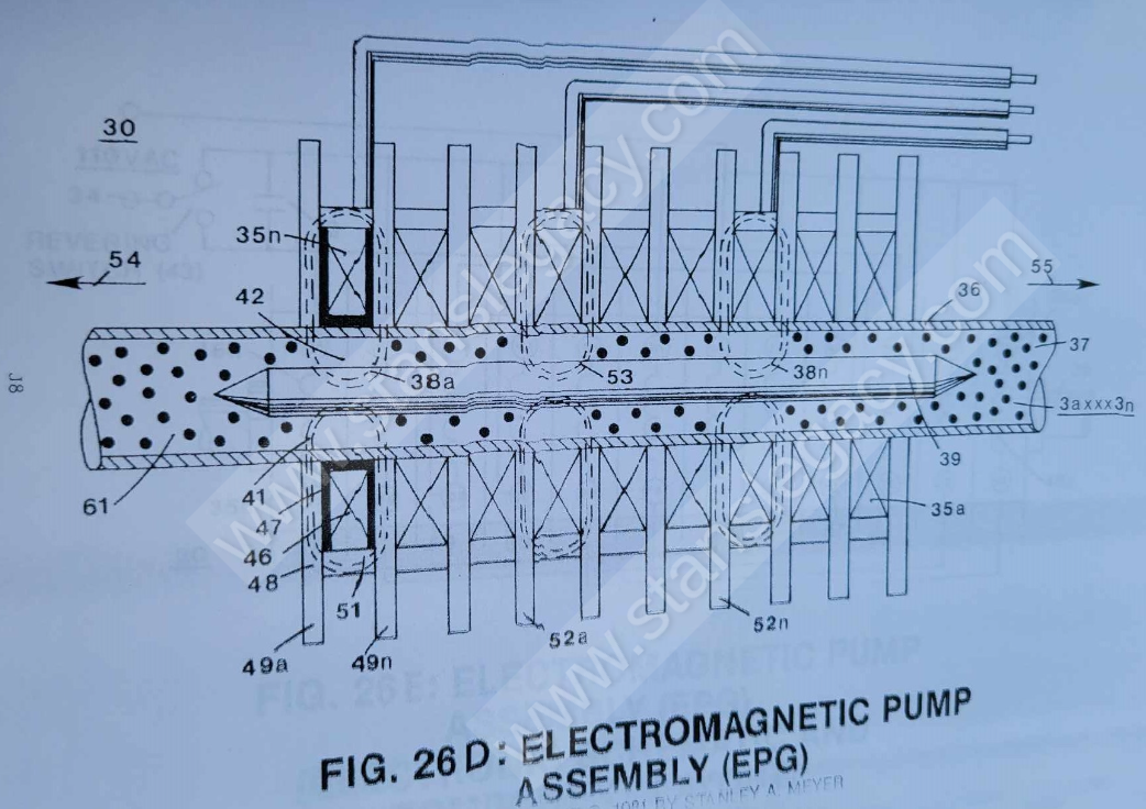](https://stanslegacy.com/uploads/images/gallery/2024-10/aSwUAQH6JJ5mVGW9-image-1729734071459.png) |
A simple **mechanical switching** (43 of Figure 26E) reverses the **sweep of fields** (38a xxx 38n) and moves the direction of **fluid-medium** (3) travel.
Double-phase or three-phase control is applicable to force control that would be needed for mechanical applications.
Output Force (magnetic field deflection to move mass) can be extended to beyond 300 pounds under normal duty loading.
Three-phase operations. Stator Assembly (30a xxx 30n) can be combined or built specially for higher forces.
##### **P) Electromagnetic Pump Assembly: Operational Parameters** **Force vs. fluid-medium (3) displacement:** Uniform during movement and recycling. **Force and speed controllability:** Force is directly proportional to power and voltage squared. Force can be controlled by varying input voltage, resulting in variable speed control. **Current vs. fluid-medium displacement:** Uniform during movement and recycling. No high in-rush current. **Fluid-medium (3) velocity:** Fluid-mass acceleration occurs in less than 10 milliseconds and reaches a controlled speed (or velocity) during recycling. The time or distance needed to perform normal operational speed of fluid-velocity depends upon net force "applied" and fluid-mass being moved. Normal operating velocity is 30 fps for **single-phase units** (30) and 90 fps for **three-phase units** (30/30/30). **Force vs. duty cycle capabilities:** Duty cycling (*stator on-time*) is only limited to heat dissipation ability. ##### **Q) Electrical Pump Assembly: Design Specs** **Coil** (46) is wound (*400 turns 30 ga. insulated wire*) on **molded nylon bobbin** (47) that is placed inside a **magnetic "shunt-assembly"** (48) and slipped over said **tubular bearing** (36), as illustrated in Figure 26E as to Figure 26F and Figure 28.| [](https://stanslegacy.com/uploads/images/gallery/2024-10/M7inajv1n4YpLydq-image-1729712616828.png) | [](https://stanslegacy.com/uploads/images/gallery/2024-10/0WPinvE1yJJT8VVJ-image-1729699457603.png) |
A second **magnetic bar key** (39) is inserted into said **tubular pathway** (36) and properly aligned to said **coil-array** (30/30)... forming an **air gap** (42) between said **tubular surface** (36) and said **Magnetic Key Assembly** (39)... completing the field effect forming said **cavity** (41)... and structuring **pulsing effect** itself (35).
| [](https://stanslegacy.com/uploads/images/gallery/2024-10/M7inajv1n4YpLydq-image-1729712616828.png) | [](https://stanslegacy.com/uploads/images/gallery/2024-10/jV5842wLneom6bjK-image-1729568848276.png) |
Said **metal discs** (49a/49b) are extended beyond said **Magnetic Key** (51) to provide **open air fins** (52a xxx 52n) for the purpose of heat dissipation during coil pulsing.
| [](https://stanslegacy.com/uploads/images/gallery/2024-10/iA8DbdlGxg2gL0pE-image-1729624457766.png) | [](https://stanslegacy.com/uploads/images/gallery/2024-10/0WPinvE1yJJT8VVJ-image-1729699457603.png) |
Typical cross-sectional diameter of said **tubular pathway** (36) may vary up to and beyond 1/2 inch O.D.
--- ##### **R) Electromagnetic Pump Assembly: Electrical Activation** Voltage applied to **coil** (46) causes current flow and creates **magnetic field** (41) that passes through said **magnetic shunt** (48)... causing magnetic **flux-lines** (48) to align said field effect to said **fluid-mass** (3). Once the **magnetized** **fluid-mass** (3) is aligned by said **magnetic deflection (*pulsing*) attraction forces** (53 of Figure 26C) and "locks-onto" said permanently magnetized **fluid-medium** (3a xxx 3n). > Electromagnetic fields emanating from a **coil-magnet** (like 46) and a **permanent magnet** (like 4) are the same in electromagnetic characteristic. [](https://stanslegacy.com/uploads/images/gallery/2024-10/M7inajv1n4YpLydq-image-1729712616828.png) Wiring of said **coils** (46a xxx 46n) in proper sequence (see wiring schematic Figure 26E) with said capacitor (33) produces a **sweeping magnetic wave** (38a xxx 38n) across said **fluid-mass** (3), thus allowing said **fluid-mass movement** (54). Applied AC electrical power (110 Vac 60 Hz) to said **capacitor** (33) provides an electrical charge/discharge cycling rate that allows adjacent coils to be fired in proper sequence.In other applications, said **charging capacitor** (33) can be replaced by an AC Triac triggering circuit or SCR triggering circuit.
In terms of electrical reversibility, **Directional Switch** (43) applies AC electrical power to opposite side of said **capacitor** (33) to cause said **magnetic sweeping field** (38a xxx 38n) to reverse in **direction** (55). Coil-arrangement as to **Electrical Hookup** (56/57 and 58/59) of Figure 26E provides temporary "Breaking Power" during switching operations.By simply varying applied voltage and pulse triggering rate, likewise varies **magnetic mass velocity** (61).
To reach maximum acceleration performance, said **Magnetic Keeper Bar** (39) moves said moving **fluid-mass** (3) closer to said **bearing surface** (36)... enhancing **magnetic attraction force** (53).
To obtain maximum operational efficiency of said **Stator assembly** (30), said **magnetic keeper-bar** (39) also acts as a magnetic field spoiler by disrupting **particle alignment** (15a xxx 15n of Figure 30)... **collapsing magnetic field** (4/11) prior to particle entrance into said **Stator Assembly** (30).
Said **magnetic field** (4) reforming after exiting said **Stator Assembly** (30). [](https://stanslegacy.com/uploads/images/gallery/2024-10/HkrFdxXxmCQmMROW-image-1729623833109.png) ##### **S) Electrical Particle Generator (EPG): Environmental Flexibility**By simply encasing or coating said closed loop **Electrical Particle Generator** (EPG) with a waterproof material, said electrical generator (EPG) can be used underwater or in the deepest realm of space.
# Electrical Polarization Generator PURPOSE: To produce electrical energy from natural water without consuming the water molecule atoms. # ELECTRICAL POLARIZATION GENERATOR **PURPOSE**: To produce electrical energy from natural water without consuming the water molecule atoms. [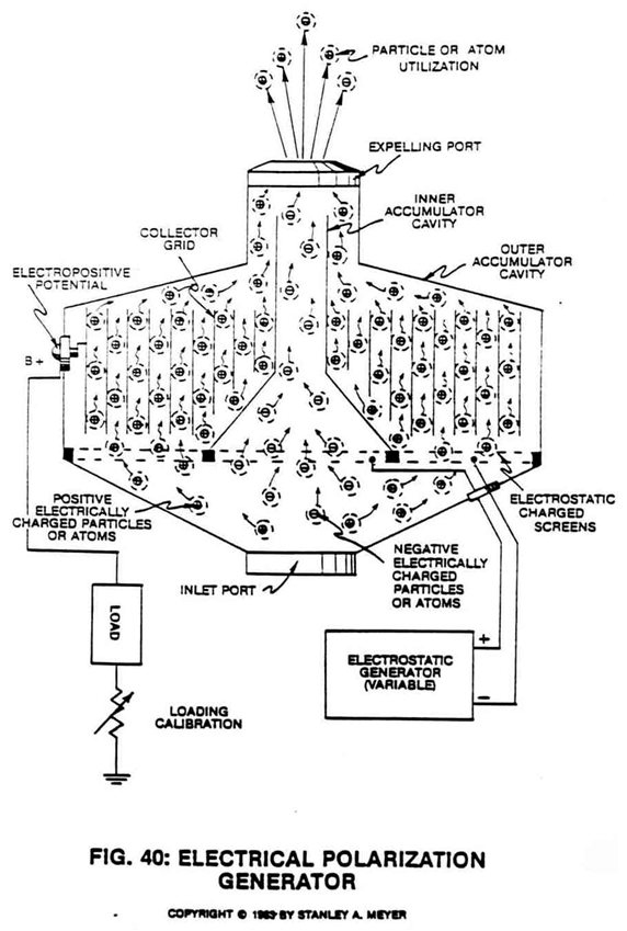](https://stanslegacy.com/uploads/images/gallery/2024-10/RsoThuKNtuY5nskP-image-1729464850034.png) **Circuit State**: Moving **electrically charged atoms** (1/2) through an **electrical grid system** (50) inserted into a **dual gas accumulator cavity** (30/40) separated by an **ambient air filtering screen assembly** (20A) of opposite voltage polarity… forming **Electrical Polarization Generator** (90), as illustrated in Figure 40 as to Figure 8 subtitled “Regenerative Energy Feedback Module.” ##### **ELECTRICAL CHARGED GASES** As shown in Figure 20F as to line graph 20FA and pulse train 20FB section A, the liberated gas atoms (Figure 24) (hydrogen, oxygen, ambient air gases) derived from natural water undergo the Electrical Polarization Process (Figure 2/3) become ionized when the opposite voltage zones (placed on opposite sides of said gas atoms) reach a certain voltage intensity… causing the negative electrically charged nucleus of said gas atom to be attracted to said positive electrical voltage zone… while, at the same time, the positive charged nuclei of the same gas atom is attracted to said negative electrical voltage zone, satisfying the opposite polarity attraction law of physics.| [](https://stanslegacy.com/uploads/images/gallery/2024-10/oZRWoLotIlKv3UtG-image-1729471836441.png) | [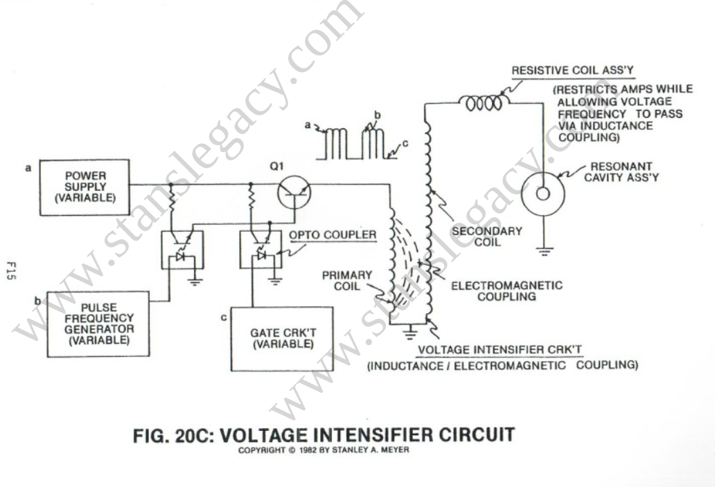](https://stanslegacy.com/uploads/images/gallery/2024-10/jEYAaYqk8gW09FG2-image-1729472339910.png) |
Increasing voltage intensity (Voltage potential by way of amp restriction) removes additional electrons from said gas atoms… at a given electron light frequency injection (nuclei light absorption).
This said **Atomic Polarization Process** further aids the electron deflection process by deflecting said electrons to a higher energy state, see Figure 20F as to Figure 20C. **Voltage Intensifier Circuit** (VXA) prevents electron replacement. The water molecule is exposed to the same voltage stimulation process. ##### **ELECTRON ENTRAPMENT** In cases where electron ejection does not occur, the laser absorbed atoms may accept the liberated and/or free-floating electrons… causing electron entrapment, see Figure 20F again. [](https://stanslegacy.com/uploads/images/gallery/2024-10/oZRWoLotIlKv3UtG-image-1729471836441.png) ##### **ION GAS FORMATION** The atoms having missing electrons now become **positive charge gas ions** (1) while atoms having more electrons than normal become **negative charge gas ions** (2). After ionic gas formation, the electrically charged gases are expelled out of said **Fuel Cell** (Figure 20YAA) as to Figure 3B and enter into said **Electrical Polarization Generator** (90) of figure 40.| [](https://stanslegacy.com/uploads/images/gallery/2024-10/yRRy0MKUNLI1yHEm-image-1729045880432-31-14.png) | [](https://stanslegacy.com/uploads/images/gallery/2024-10/RsoThuKNtuY5nskP-image-1729464850034.png) |
**Accumulator cavities** (30/40) are electrically isolated from one another to prevent electrical discharging of said gas ions during application use.
##### **ELECTROPOSITIVE POTENTIAL** Since the **positive electrically charged gas ions** (1a xxx 1n) are exposed to said **Collector Grid** (50) constructed of electrical conducting plates material (6a xxx 6n) such as stainless steel T304, the **Collector Grid Assembly** (50) becomes positive electrically charged due to the **Electrical Skin Effect** between said charged gas ions and said **electrical conduction plate** (6).**Electrical Skin Effect** occurs when the electrical field that surrounds the gas ions touches the **electrical conduction plate** (6), as illustrated in Figure 40.
The resultant **positive electrical potential** (7) is now applied to **positive electrical terminal** (8).To increase said **positive electrical potential** (7) (voltage potential) across said **electrical terminal** (8), simply increase the surface areas of said **electrical plates** (6a xxx 6n) while increasing the number of **electrically charged particles** (1a xxx 1n) touching said expanded collection plates.
**PERFORMING ELECTRICAL WORK** Since electrical differential exists between **electrical ground** (11) and said **positive electrical terminal** (8), electrical work (consuming electron flow) is now performed when an electrical load is placed between said **electrical points** (8/11). Said **Electrical Work** occurs when the negative electrically charge electrons from **ground connection** (11) move toward and through said **electrical load** (9) to **positive electrical terminal** (8). The traveling electrons continue along an electrical pathway (electrical conductor attached between said **terminal post** (8) and said plates) to **electrical conduction plates** (6a xxx 6n)... exposing the moving electrons to the **moving gas ions** (1a xxx 1n) of opposite electrical polarity... allowing the moving negative electrically charged electrons to be accepted by the **positive charged gas atom** (1) having missing electrons...satisfying the law of atom stability of physics.
To maintain a constant flow of electrons toward said **electrical terminal** (8), simply maintain the gas-flow through the **gas accumulator cavity** (30). To increase amp flow (*speed up electron movement*), increase said gas flow rate. Of course, amp flow is minimized between said **electrical load** (9) and said **electrical terminal** (8) since said electrical load consumes electrical power (*consuming electrons*) in the form of electrical heat. **GAS ION DISPOSAL** The **negative charged gas ions** (2a xxx 2n) passing through **gas accumulator** (40) is simply discharged through gas exit port (12) while **gas ions** (1a xxx 1n) passing through **gas accumulator cavity** (30) are discharged through a separate **exit port** (13). The expelling gases are simply recombined for hydrogen gas utilization beyond said **exit port** (12/13). # Exhibits # Exhibit BX1 #### EMERGING TECHNOLOGY **AMAZING LASER:** Revolutionary new design of a widely used laser now combines miniature size and high power. This new type of semiconductor laser also offers unrivaled reliability and lower cost. It’s expected to have a broad range of applications—data processing, satellite communications, medicine, and, ultimately, computers that process information using *light* instead of *electricity*. **Background:** In the past 25 years, lasers have gone from an esoteric curiosity to one of today’s most important, versatile, and fastest-growing technologies. There are now dozens of different lasers—from low-power gas lasers used in eye surgery to powerful X-ray lasers expected to form the backbone of the Star Wars program. The most commercially significant of all, however, is the semiconductor, or diode, laser. It's the workhorse of the electronics and telecommunications industries—used in compact disk players, fiber optic communications systems, etc. Diode lasers are prized for their compactness and high reliability. They resemble microchips and are made from the same semiconductor materials as chips. **Drawback:** The laser-on-a-chip is tricky to manufacture (tiny, faceted mirrors must be fabricated along its edges), and it produces only low-power beams. **Breakthrough:** New diode laser design produces beams many times more powerful than today’s models—out of the same size package. It’s also cheaper and less expensive to manufacture. Known as a *surface-emitting diode laser*, it uses its entire surface (not just the mirrored edge) to create a beam. A tiny grid, etched in the semiconductor material, precisely “tunes” emitted light into a single laser beam. This beam is more than **100 times** more tightly focused than that produced by standard (edge-emitting) diode lasers. **Added advantages:** Because the new lasers eliminate the need for precisely machined and focused micro-mirrors, they’re also more reliable. In addition, surface-emitting diode lasers can be optically “locked” together to create a very high-power laser. **Status:** Commercial versions of the new laser should be available in one to two years. **Research leader:** Jacob M. Hammer, Ph.D., RCA Laboratories, David Sarnoff Research Center, Princeton, NJ 08540. --- #### YEAST—RISING IN A NEW WORLD: Baker’s yeast—the same organism that has leavened bread and fermented wine for more than 6,000 years—is now beginning to make big payoffs in the world of biotechnology. It’s making genetic engineering easier, more productive, and more profitable for scientists and biotech and pharmaceutical firms. **Background:** Genetic engineering centers upon the ability to modify the genetic makeup of simple organisms. Scientists select an organism and insert DNA (genetic instructions) that corresponds to the production of a particular protein, thereby “commandeering” the organism to do their bio... (ends on this page). © 1987 Boardroom Reports, Inc. # Exhibit E3 [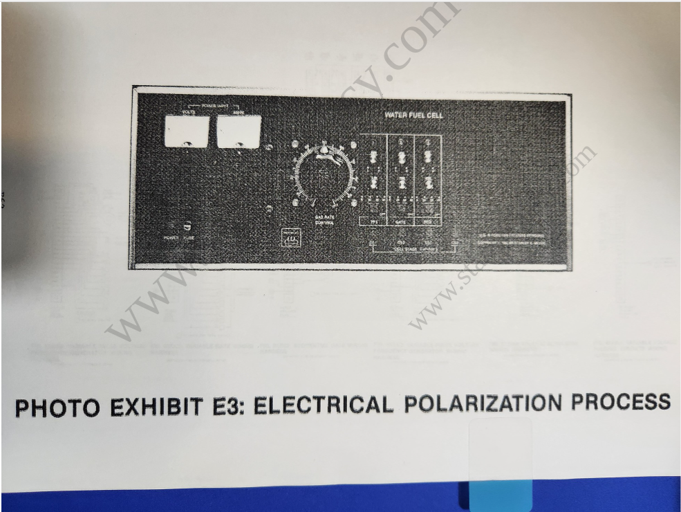](https://stanslegacy.com/uploads/images/gallery/2024-10/VL4wsMDq0zPQQsNP-image-1729211494270.png) # Exhibit E 2 A [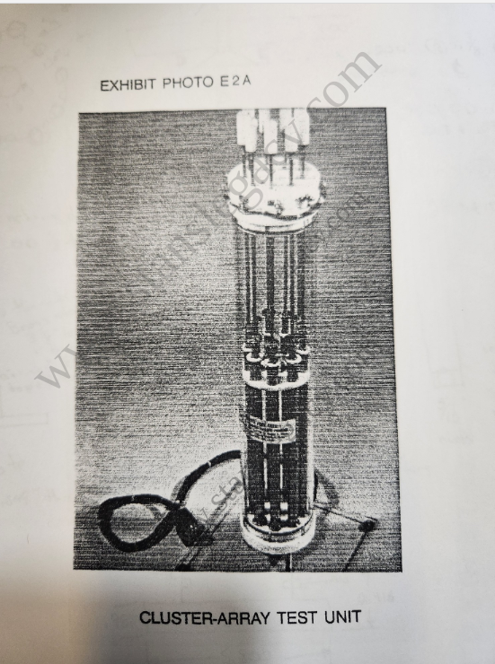](https://stanslegacy.com/uploads/images/gallery/2024-10/knvqyCwi0xnnBJH7-image-1729211613881.png) # Exhibit E 5 A [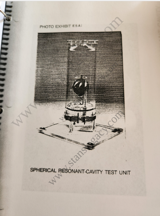](https://stanslegacy.com/uploads/images/gallery/2024-10/waN5cb3zGEpxsCeM-image-1729211671574.png) # Exhibit E 4 A [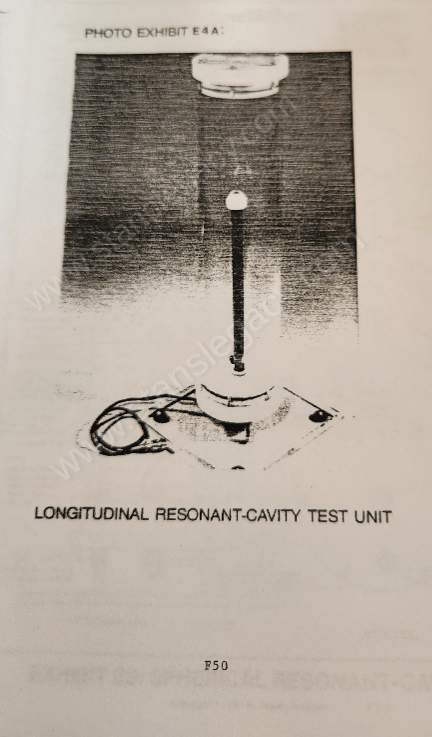](https://stanslegacy.com/uploads/images/gallery/2024-10/fiReSGTt7PTnleZ2-image-1729284645727.png) # Exhibit E 4 [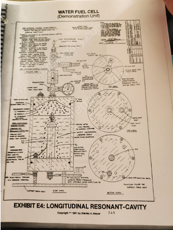](https://stanslegacy.com/uploads/images/gallery/2024-10/LvL2FlGe8MIVRpZf-image-1729284719318.png) # Exhibit E 5 [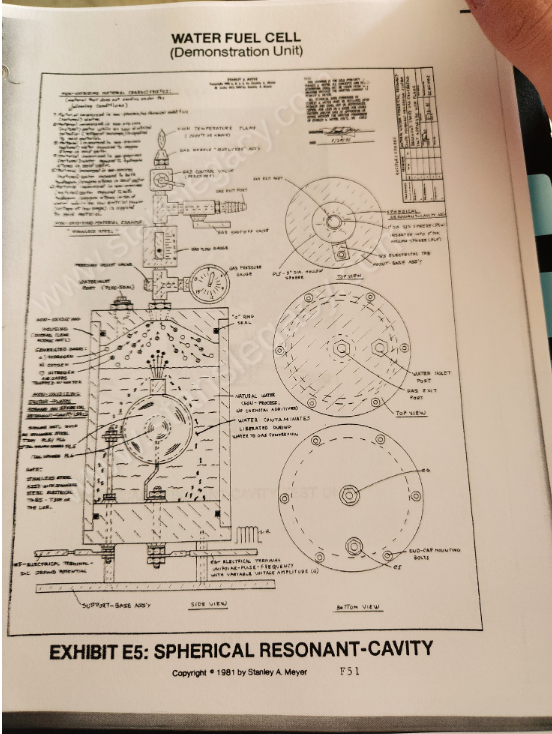](https://stanslegacy.com/uploads/images/gallery/2024-10/XpqjlONsRE7Cg71l-image-1729284848619.png) # Exhibit E 6 [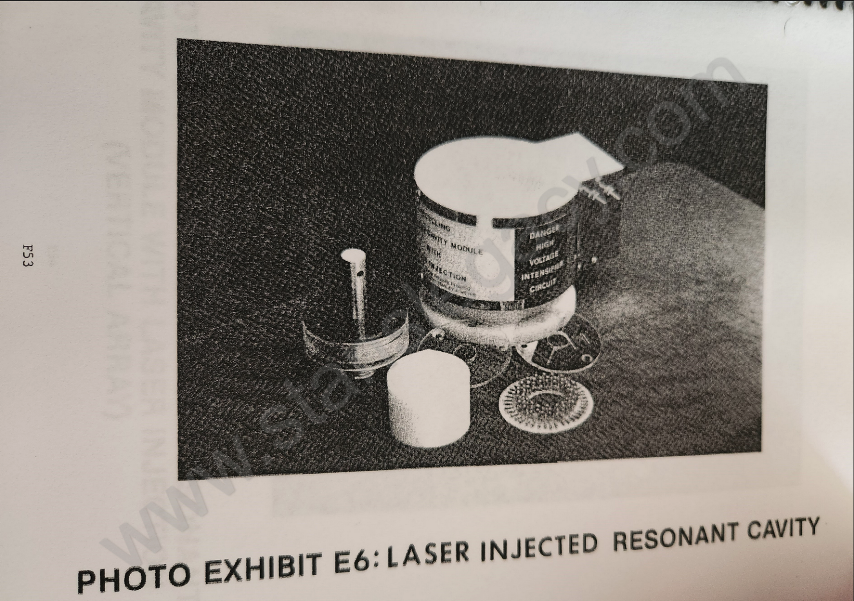](https://stanslegacy.com/uploads/images/gallery/2024-10/QYpoVAXIFlWbbnMF-screenshot-2024-10-20-at-20-43-04.png) # Exhibit E 7 [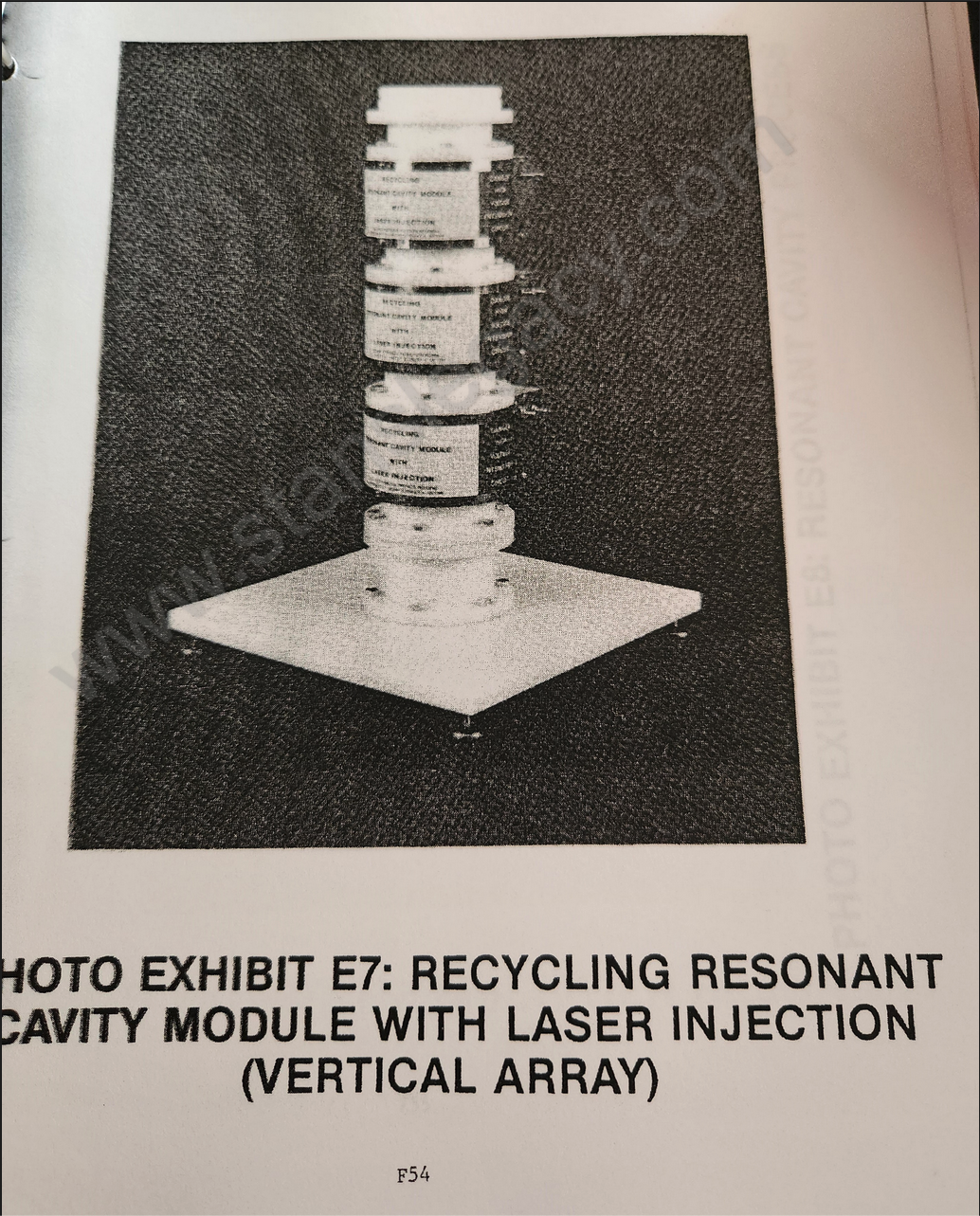](https://stanslegacy.com/uploads/images/gallery/2024-10/YQmzzQVB1GAaWtYZ-image-1729471449147-44-06.png) # Exhibit E 9 [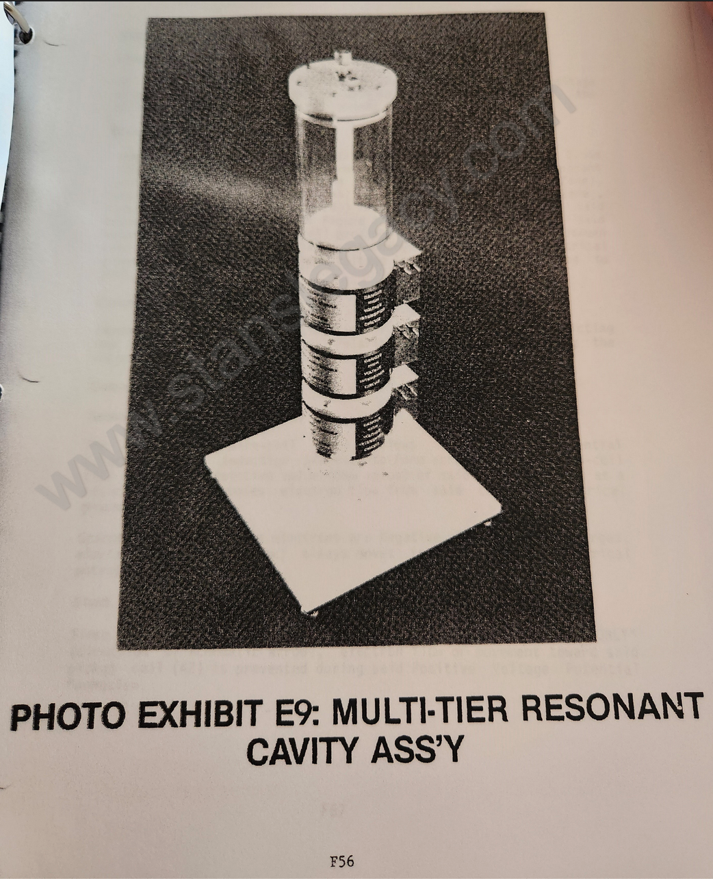](https://stanslegacy.com/uploads/images/gallery/2024-10/Ok5jnV3HJXlpKsl4-image-1729471487816-44-45.png) # Exhibit ZX & ZY [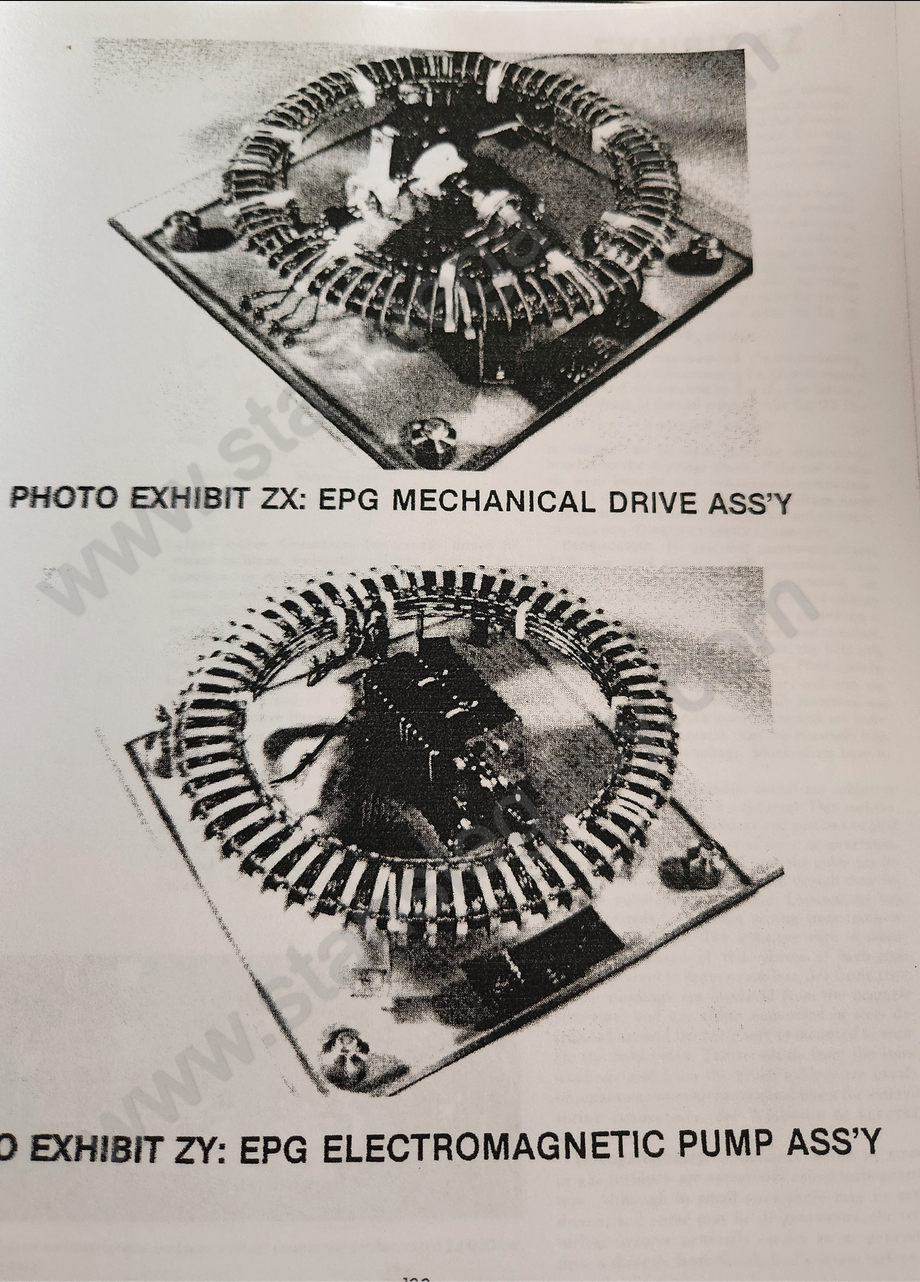](https://stanslegacy.com/uploads/images/gallery/2024-10/EGuN1IaKBjfoDeHE-image-1729471661056.png)