A voltage change cannot occur until the stored charges can be altered through current flow... if allowed.
Component arrangement of said Voltage Intensifier Circuit 9XA as to 20YA retards or prevents amp flow.| [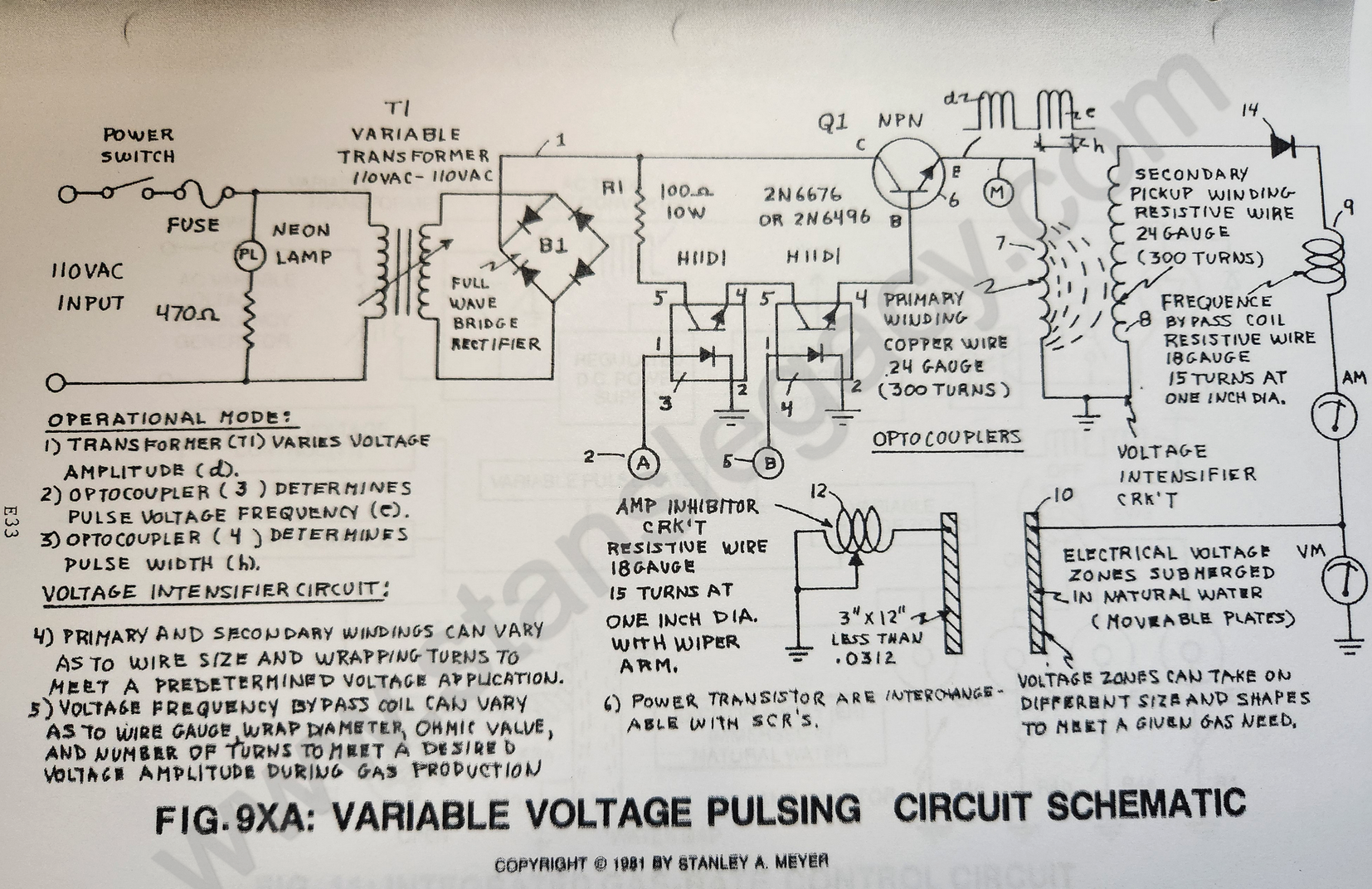](https://stanslegacy.com/uploads/images/gallery/2024-10/l16N0eiYU2kdSwXM-image-1729045722557-28-36.png) | [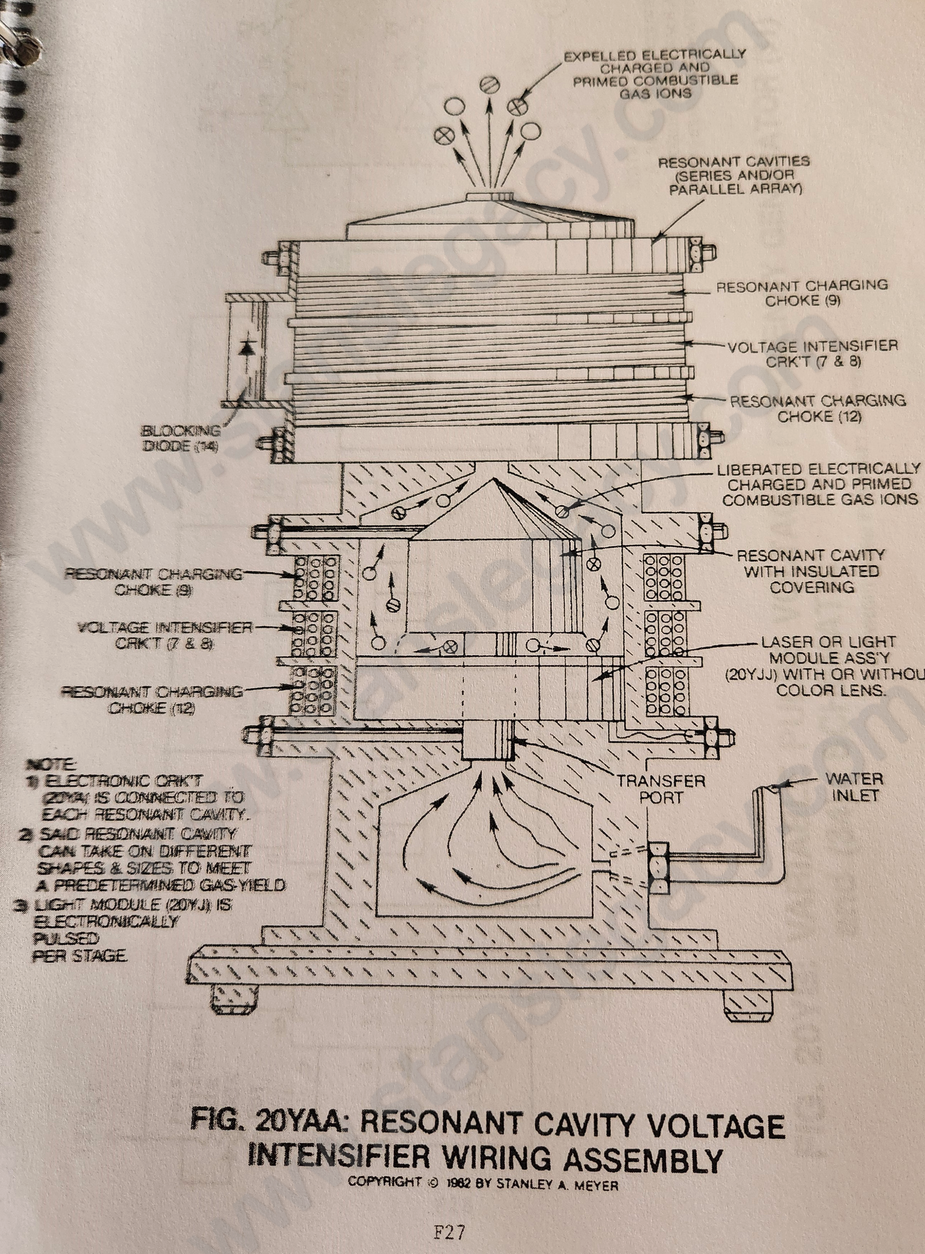](https://stanslegacy.com/uploads/images/gallery/2024-10/yRRy0MKUNLI1yHEm-image-1729045880432-31-14.png) |
**Scientific Fact:** Distilled water is an insulator to the flow of amps; natural water has less than 20ppm of any type of contaminates and maintains a high dielectric constant.
--- ### **Resistor Component (47)** Another **Resonant Charging Choke** (47) is placed between said **negative voltage zone** (44) and said **circuit electrical ground** (48) to help maintain the resistance value (voltage level) within the Resonant Cavity during charging. The resistive value of said **wire-coil** (47) prevents amp flow while performing in like manner as a Resonant Charging Choke. --- ### **Resonant Action as to Voltage Stimulation of the Water Molecule** Resonant Action occurs when the Voltage Intensifier Circuit 9XA as to 20YA set up a circuit condition whereby the **inductive** (43/45) and **capacitive reactance** (44/47) (or circuit impedance) components of said circuit have been balanced. The Circuit is "tuned" to resonance at a certain pulse voltage frequency (reaching resonant "Q")... allowing voltage stimulation of the water molecule... performing the Electrical Polarization Process at **Resonant "Q."****Scientific Fact:** The ability of an inductor and a capacitor in a series-resonant circuit delivers a voltage several times greater than the input voltage.
--- ### **Resonant Cavity Structure vs Applied Pulse-Voltage** By simply varying the applied voltage amplitude in direct relationship to a variable pulse voltage frequency, the Resonant Cavity Structure can take on different shapes to maximize voltage stimulation of the water molecule to release hydrogen gas under control means.Voltage range from zero to 5,000 volts; pulse-voltage frequency range from zero to one megahertz; amp flow being restricted to a minimum value.
--- ### **Dual Voltage Resonant "Q"****Low Amplitude Pulse Voltage Frequency** (54) is injected between **Pulse Voltage Frequency** (53) to keep an electrical charge on said water molecule during Resonant "Q."