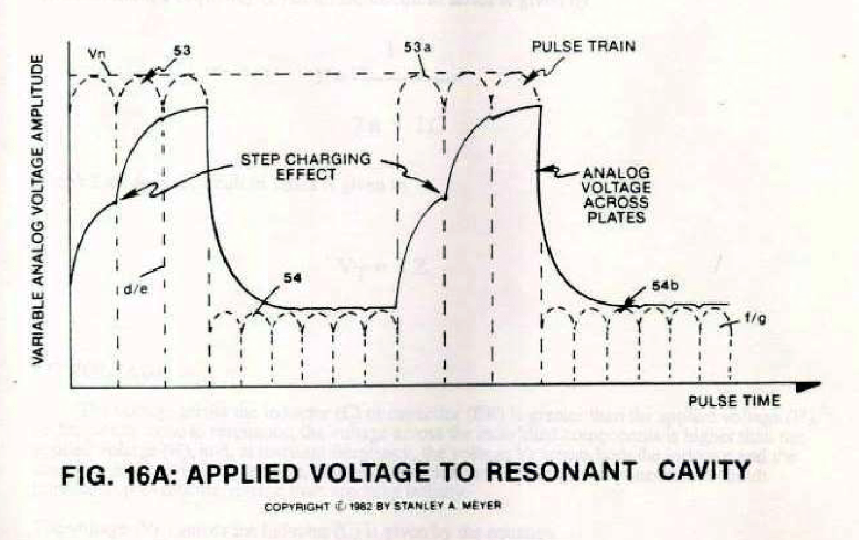
In reference to Voltage Intensifier Circuit 9XA as to dual-voltage schematic 20YA and pulse voltage waveform 16A/20YA Section AA, the following operational parameters exist:
[](https://stanslegacy.com/uploads/images/gallery/2024-10/teWQHV77FyNS7NVn-image-1729532146629.png) #### **Electronic Interfacing Circuit:** - **Secondary Pickup Winding** (resistive wire coil) (42) - **Blocking Diode** (14) - **Resonant Charging Choke** (resistive wire coil) (43) - **Resonant Cavity Inner Surface** (45) (forming a Positive Electrical Voltage Zone), - **Resonant Cavity Outer Surface** (44) (forming a Negative Voltage Zone) - **Voltage zones surface area** (44/45) form the Capacitance value of said **Resonant Cavity Assembly** (4) of Figure 12. Natural Water inside said **Resonant Cavity Assembly** (44/45) provides the dielectric value between said **voltage zones** (44/45), **resonant charging choke** (47) to electrical ground forms and completes the **Voltage Intensifier Circuit** 9XA as to 20YA.| [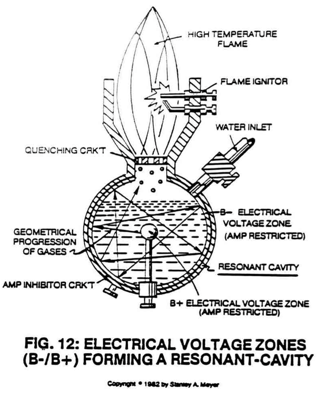](https://stanslegacy.com/uploads/images/gallery/2024-10/ZAhFd74xUdz1mzin-image-1729267471403.png) | [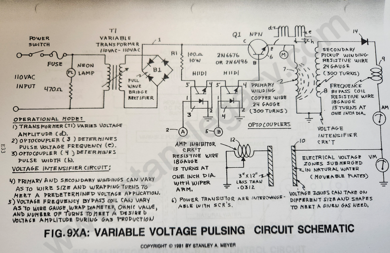](https://stanslegacy.com/uploads/images/gallery/2024-10/l16N0eiYU2kdSwXM-image-1729045722557-28-36.png) |
**Scientific Fact:** Since electrons are negatively electrically charged, electron flow (amp flow) always moves toward positive electrical potential... if allowed.
--- ### **Block Diode (14)** Since **Blocking Diode** (14) conducts electricity in one direction "ONLY" (*direction of schematic arrow*), electron flow or movement toward said **pickup coil** (42) is prevented during said **Positive Voltage Potential** formation.