Integrating dual-pulsing circuit (33) (34) (38) (39) (40) to voltage intensifier circuit (Figure 9) previously described), as shown in Figure 20C.
[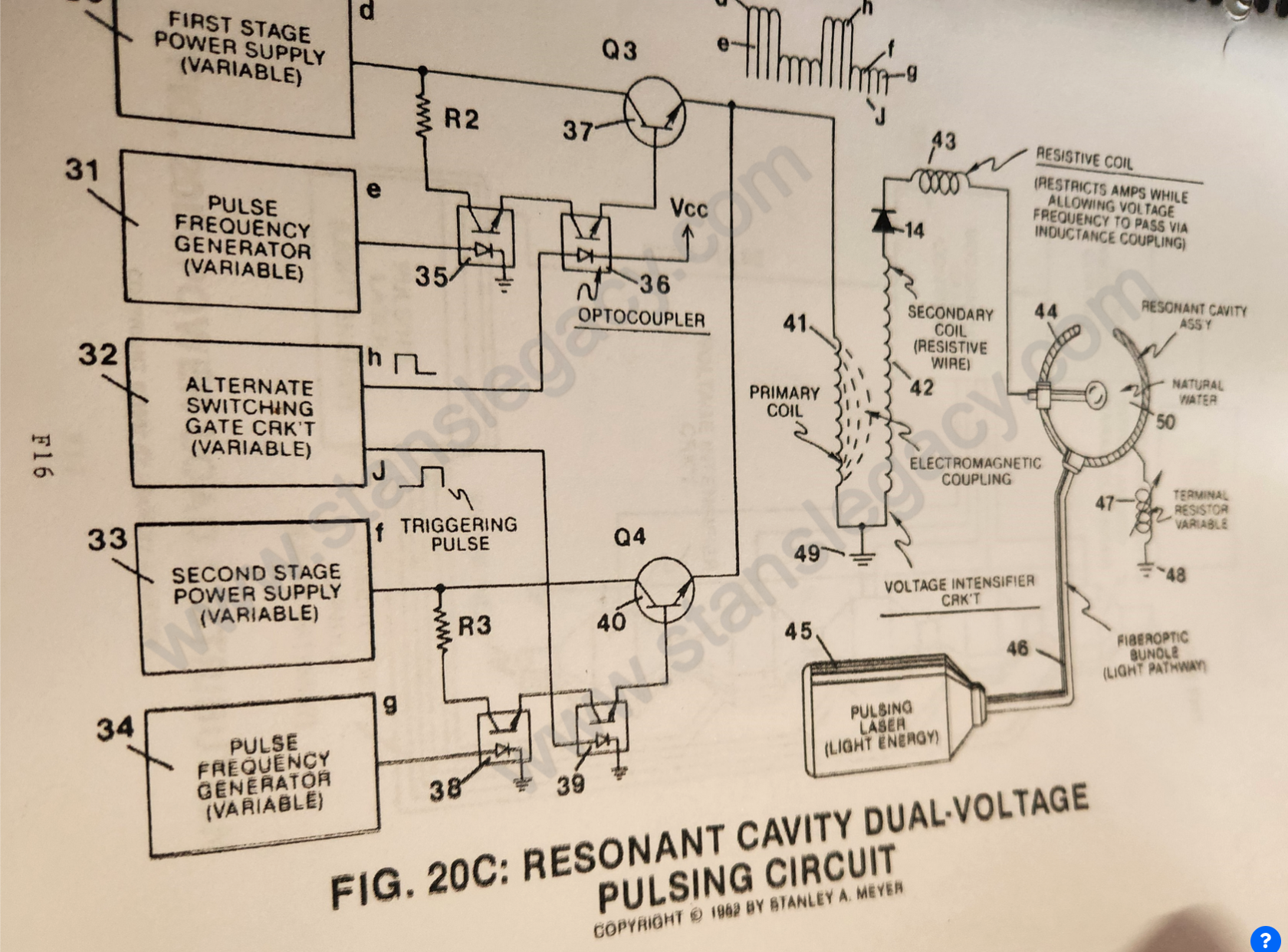](https://stanslegacy.com/uploads/images/gallery/2024-10/8giY0Hye9eZJ1C0K-image-1729052412177-20-08.png)As shown in Figure 20C. **variable gate circuit** (32) is a two-state switch device which is directly linked to both **opto-coupler** (36) and **opto-coupler** (39). As (H) near ground or low state (0 volts), **opto-coupler** (36) is triggered on. allowing **pulse voltage frequency** (d) as to (e) to form. Once said **gate circuit** (32) changes state (low to high voltage or versa), trigger pulse (J) turns on **opto-coupler** (39) to form **voltage wave form** (f) as to (g). **Triggered pulse** (H) is now terminated, switching off said **wave form** (d) (e).Repeating said alternate gate switching produces **dual-voltage pulse-train** (51) of Figure (16).
[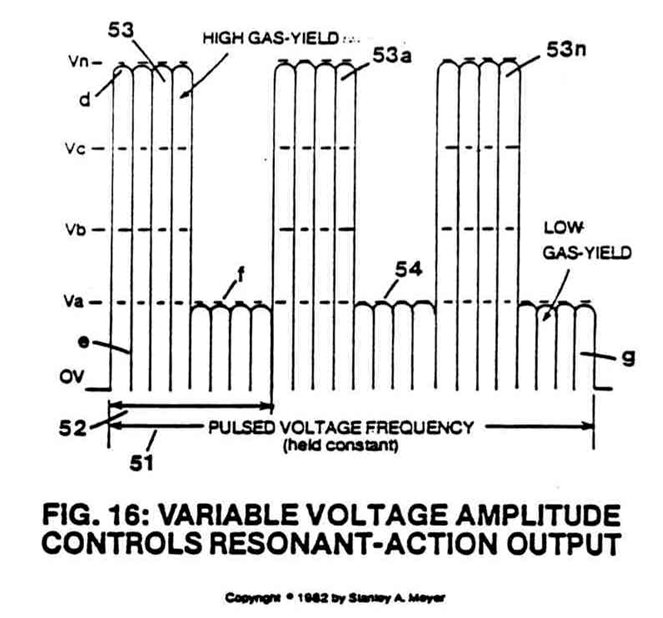](https://stanslegacy.com/uploads/images/gallery/2024-10/V1GF6JMkggg31Ckr-image-1729267018556.png) **Wave form** (d) (e) and **wave form** (f) (g) now **pulse-duty** (52) which is varied from one duty-pulse one hundred duty-pulses (establishing **pulse-train** 51) via **gate circuit** (32) *(tenth and eleventh steps to voltage attenuation)*.The reoccurring **duty-pulse** (52) is now attenuated to provide maximum gas-yield while minimizing amp flow.
**This is accomplished in several ways:**1. **Gated pulse** (H) as to **gated pulse** (J) is proportionally changed to "concentrate" or "expand" said applied voltages to said resonant cavity. Said **gated pulse train** (53, on time) as to (54, off time) is adjustable from 1% to 100% duty time.
As **on-time** (53) increases, **off-time** (54) proportionally decreases, allowing more **voltage pulses** (53) to be applied to said **resonant cavity** (44).
To reduce the number of **voltage pulses** (53), simply reverse the pulse-train adjustment of said **gate control circuit** (32).
Once the gated **pulse-train** (51) is set as to maximizing gas production, the **gated duty-cycle pulse** (52) is now varied from **one duty-pulse per second duration** (52a) to **one hundred duty-pulses per second duration** (52n) to help restrict amp flow.2. Said **voltage amplitude** (d) is varied to increase gas-yield. After said **voltage amplitude** (d) is stepped up, applied voltage range to said **cavity** (44) is from less than one volt to 5,000 volts or more.
3. Said **voltage pulse frequency** (e) is now varied from **1 Hz** to **1 MHz** and more, increasing gas-yield still further.
[](https://stanslegacy.com/uploads/images/gallery/2024-10/V1GF6JMkggg31Ckr-image-1729267018556.png)Said **voltage amplitude** (f) is varied to sustain and compounding-action within said **resonant cavity** (44). Said **voltage amplitude** (f) is adjusted as to cavity-size. An increase in voltage amplitude (f) is required as cavity-size increases. 4\. Once compounding-action is properly maintained, **voltage amplitude** (f) is adjusted "no" further to keep amp flow to a minimum (*twelfth step to voltage attenuation and eleventh step to amp restriction*).Once step up, **voltage range** (f) is the same as **voltage range** (d), one volt to 5,000 volts or more.
**Caution:** Said **voltage amplitude** (d) should never be less than said **voltage amplitude** (f) in order to maintain said compounding action.
5. Said **voltage pulse frequency** (g) is now adjusted from 1 Hz to 1 MHz or more to reduce amp flow still further while maintaining said compounding-action.
6. Said **variable gate circuit** (55) of Figure 20D is now retrofitted to said **dual-pulsing circuit** 20C to extend gas production beyond the limits of a single resonant cavity, keeping power loading to a minimum while adding another gas control feature.
| [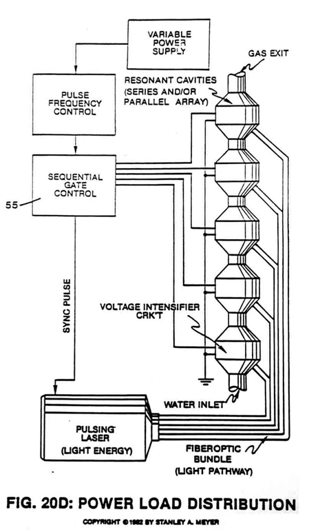Figure 20D](https://stanslegacy.com/uploads/images/gallery/2024-10/rrn3DYKgMU8J9mUg-image-1729267106297.png) | [](https://stanslegacy.com/uploads/images/gallery/2024-10/8giY0Hye9eZJ1C0K-image-1729052412177-20-08.png)Figure 20C |