| [](https://stanslegacy.com/uploads/images/gallery/2024-10/XjFBmgimCge8AATu-image-1729265842805.png) | [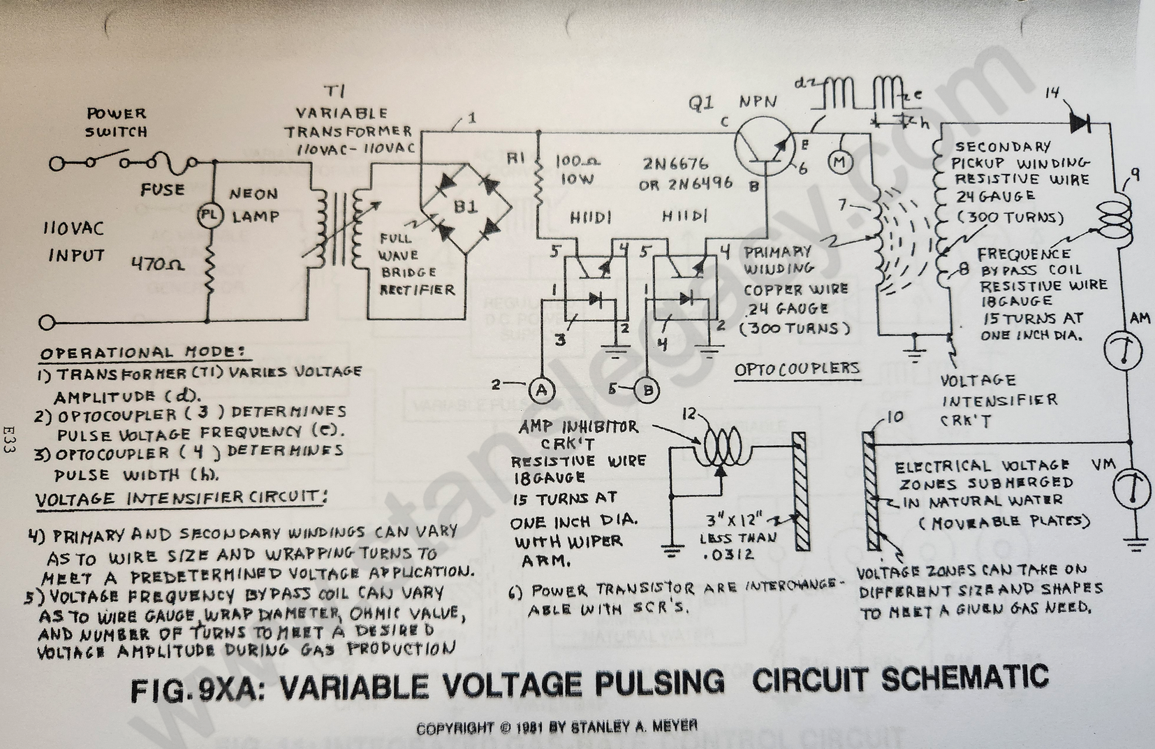](https://stanslegacy.com/uploads/images/gallery/2024-10/l16N0eiYU2kdSwXM-image-1729045722557-28-36.png) |
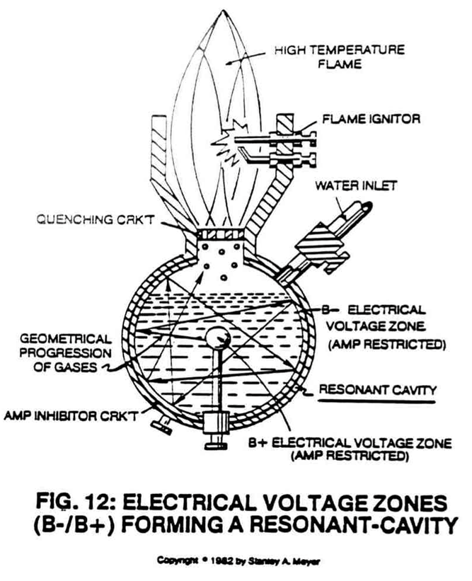
**Purpose:** To form opposite Electrical Voltage Zones while restricting amp flow during the Electrical Polarization Process (splitting the water molecule by way of Voltage stimulation).
##### Component Interaction: **Secondary Pickup Winding (42):** The **resistive wire-coil** (42) allows a voltage potential (electromagnetic induction process) to form across said **pickup-coil** (42) while the resistive value (Ohm value) of said coil-wire acts as a resistor which opposes electron flow from said **circuit electrical ground** (48). > **Scientific Fact:** Since electrons are Negative Electrically Charged, electron flow (amp flow) always moves toward positive electrical potential... if allowed. **Block Diode (14):** Since **Blocking Diode** (14) conducts electricity in one direction "ONLY" (direction of schematic arrow), electron flow or movement toward said **pickup coil** (42) is prevented during said Positive Voltage Potential formation. [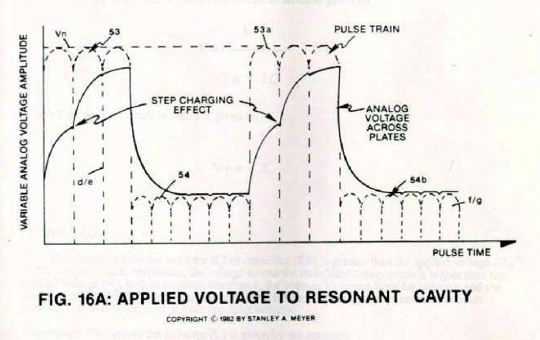](https://stanslegacy.com/uploads/images/gallery/2024-10/CwBCD5eWdC7PdMTU-image-1729562258820.png)**Resonant Charging Choke (43):** Said **Resonant Charging Choke** (43) is a Modulator Inductor which sets up an oscillation of a given charging frequency (voltage pulsing rate) with the effective capacitance of a pulse-forming network in order to charge a line to a high voltage. See Modern Dictionary of Electronics 6th Edition by Rudolf F. Graf. The resistive value of said **Charging Choke** (43) acts as a resistor... preventing amp flow still further. **Electrical Voltage Zones (44/45):** Said High Voltage Output from said **Resonant Charging Choke** (43) forms a Positive Electrical Voltage Pulse Potential (voltage zone) across said **voltage surface area** (45) immersed in natural water, see step-charging graph 16A as to 20YA Section AA again. > **Scientific Fact:** Stainless Steel Material T304 forming said **voltage zone** (45) does "NOT" chemically interact with liberated hydrogen, oxygen, and ambient air gases in natural water when exposed to a voltage potential during amp restrictions. **Capacitance:** Capacitance value is formed between said **conductor plates** 44/45 (conducting medium between two plates) of natural water is relatively high.Capacitance opposes any change in circuit voltage.
A voltage change is delayed until the stored charges can be altered through current flow... if allowed.
Component arrangement of said **Voltage Intensifier Circuit** 9XA as to 20YA retards or prevents amp flow. > **Scientific Fact:** Distilled water is an insulator to the flow of amps; natural water has less than 20ppm of any type of contaminates and maintains a high dielectric constant.**Amp Inhibitor Component (47):** Another **Resonant Charging Choke** (47) is placed between said **negative voltage zone** (44) and said **circuit electrical ground** (48) to help maintain capacitance value (voltage level) within the Resonant Cavity during voltage pulsing.
The resistive value of said **wire-coil** (47) acts as a resistor while performing in like manner as a **Resonant Charging Choke** (43).| [](https://stanslegacy.com/uploads/images/gallery/2024-10/l16N0eiYU2kdSwXM-image-1729045722557-28-36.png) |