CHAPTERS
- Introductory Section
- A Preview of Water Fuel Cell Technology and This Book
- Pre-History To Development
- The Principles of Discovery
- Operational Parameters of the Invention
- Mega Watt Gas Yield
- Fuel Cell Economics
- Hydrogen Gas Utilization
- Dynamic Ways To Produce Electricity
- Spin Off Technology
- Ending Sections
Introductory Section
Preface On Development:
The Water Fuel Cell technical approach is based on the design philosophy that the same engineering design criteria of one system applies to all systems regardless of size...being a retrofit energy system...using water as fuel…and doing the following:
- Economically producing hydrogen gas on demand
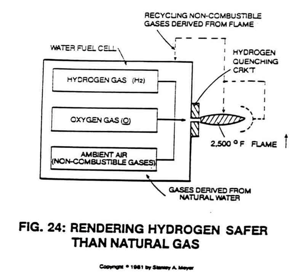
- Rendering hydrogen gas safer than natural gas
- Transporting hydrogen gas without spark-ignition
- Economically producing electricity from water
- Releasing the atomic energy-yield from hydrogen
Publications available
The Birth of New Technology: WFC Technical Brief
Explaining the Hydrogen Fracturing Process on how to use water as a new fuel-source. $25 each for U.S.; add $4 for foreign postage. U.S. Currency Only.
WFC Dealership Sales Manual:
Explaining Water Fuel Cell business format and a general overview of WFC tech-base and related spin-off developments. $25 each for U.S.; add $4 for foreign postage. U.S. Currency Only.
WFC News Releases:
Yearly news update on Water Fuel Cell business and product development activities World wide. $2 each for U.S.; add $1 for foreign postage. U.S. Currency Only.
To attend a WFC Dealership Seminar, call (614) 335-2153 before 7am or after 7 pm or Fax (614) 871-8075 for scheduling information, or mail request to Water Fuel Cell, 3792 Broadway, Grove City, Ohio 43123 to obtain a Seminar authorization pass.
History In The Making
WFC DEALERSHIP REQUEST
INFORMATION:
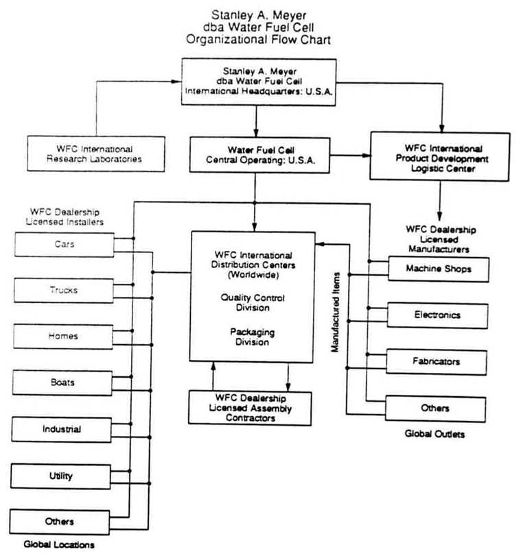
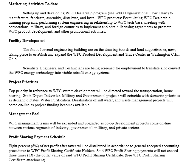
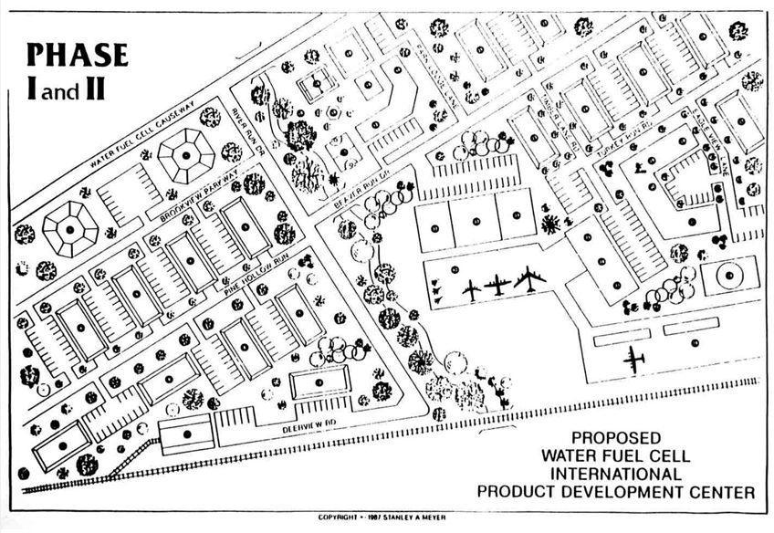
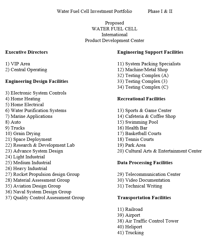
The WFC Dealership Sales program is set up to decentralize both the installation and manufacturing of the patented Water Fuel Cell tech-base by way of the WFC Product Development and Trade Center (see WFC Prospectus Flow Chart page 4).
For WFC Dealership Sales Approval and assignment, please make all inquires via WFC fax number pertaining to listed WFC Service Areas:
Home Heating & on-site Electrical: 25K population service area: County area only; Cars: Walk-in service: Metro Area Only; Trucks: Walk-in service: Metro Area Only; Boats: Walk-in service: Marina Area Only; Manufacturing: Up to three (3) Parts Only; and Sub-Assembly Contractors.
WFC Dealership purchase price is U.S. $50,000 each with U.S. $5,000 deposit...balance pay-off at the rate of 5% per sales unit profit until paid (see WFC Prospectus as per INFC Dealership Contract Agreement).
U.S. Currency (U.S. Bank only) is required on Deposit payment. The "signed" and "Filled-in" WFC Dealership Contract Agreement accompanies Deposit payment. WFC Dealership purchase is subject to WFC approval.
If you have a specific application that you would consider using the WFC technology for, please submit your request via WFC fax for project and design retrofit specifications and licensing quotes. WFC Licensing of applications are subject to WFC approval.
Refer to WFC Profit Sharing Certificate Prospectus when considering purchasing a WFC Dealership or obtaining a WFC Profit Sharing Certificate
Water Fuel Cell, 3792 Broadway, Grove City, Ohio 43123, 614-871-4173, Fax 614-871-8075
|
Notice of Technology |
National Security Laws |
Foreign Grant License |
|
All Rights Reserved Printed in the United States of America. Except in the case of brief quotations embodied in critical articles or review, no part of this WFC technical brief may be reproduced in any form or by any means, or stored in a databank or retrieval system without express written permission of inventor Stanley A. Meyer. For written approval, fax (614) 871-8075 or send request to 3792 Broadway, Grove City, Ohio 43123. All graphic illustrations were created and registered under international UCC copyright laws by Stanley A. Meyer All publishing rights reserved by Stanley A. Meyer under international UCC copyright laws. |
Patent security is enforced by National security Laws of each participating country. Do "not" make, sell, or utilize a patented process and/or device without inventor written consent and approval. International patent and copyright laws mandate the same "usage" restrictions. Information presented in this manual is not to be used for manufacturing purposes. |
The U.S. Government has allowed the WFC technology to go forward into the international market place by issuing foreign grant license No. 492680 issued July 10, 1989 and foreign grant license No. 490606 issued Nov. 15, 1989 to Stanley A. Meyer as so specified and required under the Patent Cooperation Treaty (PCT) Act. Heavy fines and imprisonment are levied on anyone who falsely claims to have participated in the development of a invention. Under the PCT Act, a Declaration of Oath must be signed, certified, and registered prior to the filing of any PCT patent application. |
PATENTS GRANTED:
|
4,389,981 |
Hydrogen gas injector system for internal combustion engine (U.S.A.) |
|
4,613,779 |
Electrical pulse generator (U.S.A.) |
|
4,421,474 |
Hydrogen gas burner (U.S.A.) |
|
1231,872 |
Hydrogen injector system (CDA) |
|
1,233,379 |
Hydrogen gas injector for internal combustion engine (CDA) |
|
1,228,833 |
Gas electrical hydrogen generator (CDA) |
|
1,227,094 |
Hydrogen/air & non-combustible gas mixing combustion system (CDA) |
|
4,613,304 |
Gas electrical hydrogen generator (USA) |
|
1,235,669 |
Controlled hydrogen gas flame (CDA) |
|
4,275,950 |
Light-guide lens (USA) |
|
1,234,774 |
Hydrogen generator system (USA) |
|
3,970,070 |
Solar heating system (USA) |
|
1,234,773 |
Resonant cavity hydrogen generator that operates with a pulse voltage electrical potential (CDA) |
|
4,265,224 |
Multi-stage solar storage system (USA) |
|
1,213,67 |
Electrical particle generator (CDA) |
|
4,465,455 |
Start-up / shut-down for a hydrogen gas burner (USA) |
|
4,798,661 |
Gas generator voltage control circuit (USA) |
|
4,826,581 |
Controlled process for the production of thermal energy from gases and apparatus useful therefore (Hydrogen Fracturing Process) (PCT) |
|
5,149,407 |
Process and apparatus for the production of fuel gas and the enhanced release of thermal energy from such gas (Electronic interfacing for the Hydrogen Fracturing Process) (Resonant Action) (USA) (WFC Project 423 DA) |
|
101761 |
Controlled hydrogen gas flame (EPO) |
|
1577992 |
Controlled hydrogen Gas flame (JPO) |
|
86439 |
Hydrogen gas injector system for internal combustion engine (EPO) |
|
1584224 |
Hydrogen Injection System (JPO) |
|
4,936,961 |
Method For the production of a Fuel Gas "Electrical Polarization Process" (US.A.) |
|
1,694,782 |
Resonant Cavity For Hydrogen Generator (MO) |
|
Allowed |
Hydrogen Gas Fuel and Management System (WFC Hydrogen Gas Management (GMS) System: PCT/US90/06513: (WFC Project 422 DA |
|
PCT/US91/ |
Water Fuel Injection System Burner Nozzle (WFC Project 424 DA) |
|
03476 |
|

A Preview of Water Fuel Cell Technology and This Book
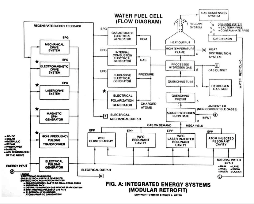 Water Fuel Cell Technical Base (graphically illustrated in Figure A) is a sophisticated integration of many energy systems integrated together to form a versatile energy package…
utilizing sun, air and water to produce electrical energy, gas, mechanical, and/or heat energy without the aid of additive chemicals or fossil fuels.
As shown in Figure A, the flow diagram is subdivided into four major areas: electrical power generators, hydrogen gas generators and processors, regenerative energy feedback systems, and reclaim and recycling systems.
A solar energy processing system (Figure 35) as well as steam resonator system (Figure 32) can be added or retrofitted to this energy grid system.
|
|
|

Each system application offers a full set of features and several applications can be used at the same time.
You can easily move from one energy system to another for a predetermined energy need.
Basically, the system grid is arranged in such a way as to produce electrical energy from natural water.
Using that electrical energy to produce hydrogen energy from water for utilization.
Since sun, water and air determine system economics, the hydrogen age can now replace the fossil fuel era.
The Water Fuel Cell of figure B is the composite expression of Flow Diagram Figure A.
 |
 |
ELECTRICAL POLARIZATION PROCESS: COVALENT BREAK-UP:
Once the atoms of the water molecule become electrically charged, the covalent bonding (sharing electrons between atoms) become non-existent since the electrically charged fields surrounding the atoms disrupt the electron movement...causing the water molecule to split into its component parts…liberating the electrically charged hydrogen and oxygen atoms for utilization (see Figures 2 and 3).
 |
 |
Basically, the positive electrically charged hydrogen atoms will momentarily attract the negative charged electrons, while at the same time, the negative electrically charged oxygen atom momentarily repels said moving electrons...preventing electron sharing between the atom…stabilizing the atom energy levels to stable state...liberating the atoms from the molecule.
EXPLOSIVE FORCE OF HYDROGEN vs JOULES OF ENERGY:
The scientific expression "gtnt” refers to the explosive force per atomic weight of hydrogen during detonation under pressure.
Joules of energy (watt-hour) should not be used in place of "gtnt" (explosive force of detonation) when equating the power yield of hydrogen undergoing atomic breakdown.
 DEFINITION OF TERMS:

The law of physics is defined as duplicating a given function continuously without change.
The ensuing chapters and pages briefly describe the basic fundamental principles of system operability and purpose of development.
See Chart C as to Flow Diagram A and Fuel Cell B.
The wording and phraseology used in this technical brief are directed to the general public to communicate a simple but profound answer to the energy crisis.
SCIENTIFIC DISSERTATION: ELECTRICAL PHENOMENA:
Physics is a composite of many fields of studies...of which the electrical phenomenon is one of them.
Voltage is electrical pressure or force within an electrical system called potential.
The words "voltage potential" herein used describe the purpose of performing work whenever different energy levels exist within the electrical system: unlike charges attract while like charges repel.
The voltage potential phenomenon is simply illustrated in the cyclotron where the electrically charged particles are accelerated by an alternating electrical field.
The brightness control on your T.V. set or computer monitor performs a similar function.
In like manner, the Water Fuel Cell utilizes the voltage potential phenomenon by setting up dual voltage zones to attract opposite electrically charged atoms: the positive electrical charged hydrogen atoms being attracted to the negative electrical charged voltage zone while the negative electrical charged oxygen atoms are being attracted to the positive electrical charged voltage zone.
This process is non-reversible since like charges repel each other.
Therefore,
A proven function becomes a Law of Definition.
Example:
Law of Motion, Law of Inductance, and so on.
Consequently, the Law of Definition as to proven function is herein used throughout this technical brief as merit of expression.
The Law of Change:
A Law of Physics establishes a proven function based on preset conditions...change any one of the conditions and the law no longer applies.
Therefore, the word groupings "voltage potential," "Law of Definition," the "Law of Change," "Electrical Polarization Process" and "gtnt" should not be taken out of context when reading this technical brief.
 |
 |
Pre-History To Development
During the middle to late 1970's, the industrialized nations of the world came to the bleak realization they no longer controlled their own capacity to produce goods and services.
This alarming condition developed because the majority of the world's remaining energy reserves were no longer in their control.
IN SEARCH OF OIL:
The Western World had enjoyed several centuries of unchecked industrialization, and showed no signs of slowing in the early 1970's. At the beginning of this industrialization period, wood was the primary source of energy. When wood became scarce and inefficient, coal became an abundant source of energy to further spur economic expansion. Coal, however, gave way to an even more efficient, cleaner, and seemingly more abundant fuel source -- oil.
Countries such as the United States were still expanding their industrial bases at such a rate that energy reserves equivalent to an Alaskan oil field needed to be discovered every 90 days so the existing fossil fuel demand could be met. However, during the middle to late 1960's, the United States also discovered that the oil pressure in its productive fields began falling dramatically. Oil fields that once supplied vast amounts of energy to the greatest industrialized countries of the world were simply beginning to produce less and less, at a time when energy needs were growing daily.
In 1965, the United States imported about five percent of its oil. By 1975, the U.S. was importing more than 40 percent of the oil it needed to maintain its industrial base. This was necessary because oil pressure in productive fields was dwindling, and it was not economically feasible to attempt secondary recovery processes to revitalize these fields.
The U.S. and other industrialized countries, such as japan, Great Britain and West Germany, could no longer count on their own energy production to keep their economies healthy, but without energy, their economies would fail—continued industrial growth would be simply impossible. Although the industrialized Western countries imported oil from Middle East nations to keep their economies afloat, they were looking forward to the day they could become energy independent through the use of the next energy source--nuclear fission.
THE FALSE HOPE OF NUCLEAR ENERGY:
Just as coal replaced wood and oil replaced coal as the primary fossil fuel, the industrialized countries were looking for the replacement of oil by nuclear energy. Although there were technical problems with the use of nuclear power plants, their use became popular. There was hope that the problems with nuclear plants would be solved as they were used. For a time, the future of nuclear power plants looked promising, but then it became clear that nuclear engineers could not solve the major problem of "the hourglass effect." Basically, the nuclear energy production process inherently caused the power plants themselves to deteriorate. The constant handling of uranium, contaminated water, steam and air quickly alters the physical properties of welds in pipes, valves and other structures within the nuclear power plants. Power plants that cost billions of dollars to build had working lives of a little more than two decades. Many of the first nuclear plants built are now being taken off line because they have absorbed as much contamination as possible without suddenly falling apart during use--causing a disastrous accident.
 CHINA DESIRES:
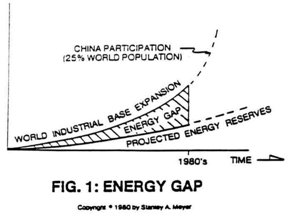
Interestingly, at the time the West began importing oil and discovering nuclear plants were not the savior they had anticipated, China began opening its doors to Western technology. What the West had accomplished in several hundred years would take China only a matter of decades to duplicate. China, with a-quarter of the world's population, was eager to obtain the same goods and services available to the rest of the industrialized nations. To do this, it was obvious they had to compete for the same oil that was already in great demand by the West; thereby perpetuating the world-wide energy gap, as shown in Figure 1.
OPEC CONSPIRACY:
Obviously, countries such as the United States did not enjoy relying upon the Organization of Petroleum Exporting Countries (OPEC) for energy. Figuratively and realistically, the Middle East oil-producing countries had the Western economies over a barrel. A sudden reduction of oil flow from OPEC to the West would create havoc with the world's industrial base. What industrial leaders feared most became a reality in the oil crisis of 1975.
The nations of OPEC realized their desert oil fields were crucial to the industrial well-being of the rest of the world. Knowing they controlled a popular commodity, and adhering to economic laws of supply and demand, the OPEC -nations reduced the amount of oil they were exporting and increased its price. Because the supply of oil was reduced, competition increased for the oil available on the market. This further caused the cost of OPEC oil to spiral upward.
The industrialized countries were paying inflated prices for oil to keep their economies stable, if not in expansion. But the OPEC oil became so costly, the goods and services produced through use of the oil also became costly—to the point that product consumption decreased, industry production decreased, people became unemployed, and economies began to falter.
THE SCRAMBLE TO DEVELOP ALTERNATIVE FUEL SOURCES:
When economic hardship became a reality due to the oil crisis, Western government began to scramble to develop alternate fuel sources to supplement dwindling oil reserves and an unrealistic nuclear energy promise. The administrations of Presidents Gerald Ford and Jimmy Carter declared energy independence as one of their paramount goals. Work was intensified to find a viable energy source through exotic solar, wind and chemical devices.
THE NEED FOR NEW TECHNOLOGY:
Industrialized countries were caught in a dilemma. While the Western industrial base was becoming more and more dependent upon energy supplies that could evaporate at any time, work was being done to develop the technology to make the exotic energy sources viable on a large scale. Unfortunately, the West became more dependent upon foreign oil daily and the exotic forms of energy production did not become economically feasible.
Solar, wind and chemical devices usually require as much, or even greater amounts of energy to use than the amount of energy produced through their use. These devices are sometimes so costly to construct because of exotic materials needed or space required -- i.e., solar panels), that even the use of high-priced oil is more cost effective. Technology relating to solar and wind energy, for example, are limited to small geographical areas. Even for persons living in desert areas, the construction of efficient solar panels to energize homes would require great space and great cost. The problem would be even more exaggerated for industrial applications.
OPEC DWINDLING OIL RESERVES:
Complicating the energy dilemma even further, many of the indicators that became apparent prior to the reduction of pressure in U.S. oil fields seem to be taking place in the oil fields of the OPEC nations. Even if OPEC keeps oil sales to the West steady and the price of the oil low, the existence of their crude reserves may be dwindling. Without the abundance of OPEC oil, economies that are momentarily healthy would begin to suffer similar problems of the 1970's, except this time it would be more disastrous.
Even so, the industrialized world depends on foreign energy to maintain its economies. And energy independence seems hopeless through nuclear or exotic energy production because of application problems and cost. Returning to coal and wood for energy would be costly and inefficient, would perpetuate the pollution problem and even be difficult because of availability of the materials.... Also, industries are geared for the use of oil--retooling and returning to the use of coal and wood would require years or even decades to accomplish.
SURVIVAL OR ELSE:
It is obvious the world needs an answer immediately to the energy problem. Industry, governments, and the average person do not have decades to wait for energy answers--especially if oil supplies from the Middle East were to be suddenly halted. If supplies were halted, there would be no time to revert back to outdated fuels or finalize technology for new fuels. Without fuel, industries would close; farmers could not plant nor harvest; economies would collapse; masses of people would starve.
Naturally, before that calamity, governments would intervene to ensure their oil supplies were maintained. The use of military force In the Middle East would be a viable alternative to economic collapse and mass starvation. Should a military confrontation occur, however, refineries, oil supply line equipment and hardware would be destroyed. Refineries, supply lines, pumping stations, etc., would take years to replace. Industrialized countries would still be without their lifeblood in the interim.
WHERE TO LOOK AND WHY?:
It is apparent that if the world community desires to maintain or improve upon its current lifestyle and avoid eminent military confrontations, a new, free and abundant energy-fuel source must be developed soon. Wood, coal, natural gas, oil, solar, wind, hydroelectric, and nuclear energy sources have limited applications, limited supply, high cost, and sometimes create undesirable by-products. A new energy source must be discovered that is readily available, economical to use, and creates no detriment to the environment. Because there is no time to waste on extensive research, the new energy source must also be flexible and adaptable to all forms of industry, residential and transportation applications.
Scientists everywhere agree that the only plausible solution to this enormous problem would be the use of one of the world's most abundant, most powerful elements on the face of the earth. That is hydrogen. After all, the earth's surface is 75 percent water, of which two-thirds is hydrogen. If only this hydrogen could be harnessed effectively, the world's energy problem would be solved almost instantly.
Although researchers hoped nuclear energy would be the answer to the planet's energy needs, the idea of using hydrogen from natural water has even a greater dream. The thought of pouring ordinary water into a mechanical device for energy is quite inviting. After all, how much does rain, snow, river or lake water cost. What ill effects could water have on the environment? The by-product of hydrogen and oxygen during the combustion process is water vapor.
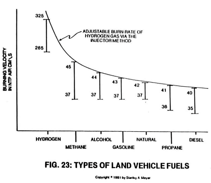
Hydrogen has been used as a fuel source before, but with limited success. Extracting hydrogen from water for use as a fuel has proven even less fruitful. There are four major technical questions that must be answered before natural water and the hydrogen it contains may be used as a fuel source. These questions are: how to produce the hydrogen (extract from water) economically; how to control the rate of the hydrogen production; how to adjust the burn rate of the hydrogen to co-equal that of fossil fuels; and how to transport the hydrogen gas without spark ignition.
Although the hydrogen has been used as a fuel, primarily in laboratory experiments and models, it has always taken a great deal of energy just to produce hydrogen or extract it from water As in other forms of experimental energy sources, hydrogen has been too costly to use. Aside from cost, just maintaining production of hydrogen has been found to be difficult. Erratic production characteristics further limit dependability. Also, hydrogen has been found to be extremely volatile (two and a half times more powerful than gasoline), even in a laboratory setting. Finally, no one has successfully demonstrated how hydrogen can be transported safely. Even if the previous problems were solved, hydrogen's use would still be limited because transmission of the gas would be impossible.
THE INVENTION:
One man, with a relentless desire to solve the world's energy problem, has now answered questions that before prevented man from using hydrogen on a wide scale. Stanley A. Meyer from Grove City Ohio, has been working since 1975, since the near disastrous oil crisis, to make the United States and other industrialized nations free from dependency on OPEC oil. He did this by inventing and perfecting the “WATER FUEL CELL”.
The Water Fuel Cell uses natural water (such as tap, lake, river, snow, rain, distilled, reservoir, pond, or even ocean water) and produces hydrogen efficiently (with hardly any energy input) for use as fuel. What's more, Meyer not only can produce the gas cheaply, he has also discovered how to control the rate of the gas production, adjust the burn rate of the hydrogen to co-equal the burn rate of fossil fuels and transport the gas safely.
Because of these landmark discoveries, the gas may be used in any application. The hydrogen gas may be used in industry, office buildings, the home, the farm, in automobiles, in airplanes, and in boats. In short, wherever energy is needed, Meyer has the capability to extract hydrogen from ordinary, natural water and use it as fuel.
Since he has the four major questions answered with his Water Fuel Cell, the system can be easily retrofitted to any existing energy- consuming device. There is no-need for re-tooling oil-using industries for exotic fuel usage. Automobiles or their engines will require only minor adjustments (hardly any to the engine) for coupling with the water fuel cell. The same can be said for homes and other buildings and their natural gas and electric furnaces. And Meyer has found a way to transport the hydrogen gas even more safely than natural gas.
When Meyer began working on the fuel cell a decade ago, his engineering, industrial, and business background provided him with the realization that highly technical developments rarely came through governments or multi-national corporations. It is historically proven that individuals or small groups of individuals see a need and are able to fill the need with their own creative thinking. United States and foreign patent law substantiates this premise by awarding the patents only to individuals.
THE ECONOMICS OF THE INVENTION:
Realizing this, it was also obvious that economic law would dictate his success. The person devising the cheapest solution to the energy problem would "win out." So, in order to be successful in bringing his new and revolutionary Water Fuel Cell into the market place without losing control of the discovery to outside economic and hostile forces, several conditions had to be met.
First, there could be no prior patents pertaining to a water fuel cell device. If someone had prior patents, his attempts to devise a system could be lawfully halted.
Secondly, the system had to be made of very readily available materials; again stressing that there is not time to develop exotic or elaborate systems. Use of "off the shelf" materials also prevents unscrupulous suppliers from effectively stalling the construction of the fuel cell.
Thirdly, the invention must be simple enough for construction in a garage or backyard. This again prevents control by elaborate manufacturing processes.
Fourthly, a person must have the capability to build a system in one day. This would allow the country to mobilize extremely fast in the face of another energy crisis.
Finally, the same engineering design criteria must apply to all of the systems, regardless of the power output of each system. The same principles had to apply to the laboratory models up to the megawatt facilities for industrial applications.
The Principles of Discovery
In order to conform with the development criteria, it is clear that hydrogen gas must be produced economically—without the use of exotic materials or complicated processes. The question loomed before Stan Meyer of how to easily separate the hydrogen from the oxygen in the water molecule. If the atoms of the water molecule could easily be disassociated, hydrogen would be a cheap and abundant fuel source.
THE PURSUIT OF KNOWLEDGE:
Meyer dealt with the prospect of how to capitalize upon the natural potential held by the hydrogen and oxygen atoms which keep the water molecule bound together. He discovered the simple yet profound principle, ELECTRICAL POLARIZATION OF THE WATER MOLECULE.
ELECTRICALLY CHARGING THE WATER MOLECULE:
 It is already known that the hydrogen and oxygen atoms by themselves may take on electrical charges.
But until now, no one discovered that by simultaneously exposing the water molecule to one positively charged and one negatively charged electrical voltage zone, the unlike hydrogen and oxygen atoms assume opposing electrical characteristics, equal in magnitude and potential, thereby stabilizing the electrical polarity of the water molecule into existence. In the water molecule, the two hydrogen atoms take on a positive (+) electrical care and the one oxygen atom takes on a negative (-) electrical charge, thereby satisfying the two basic laws of physics...for every action there is an equal and opposite reaction, and that all things must reach a stable state, as so illustrated in Figure 2.
 Although the molecule, is stabilized, in electrical polarity by the simultaneous application of the two oppositely charged voltage zones, the bond between its atoms is greatly weakened in this process.
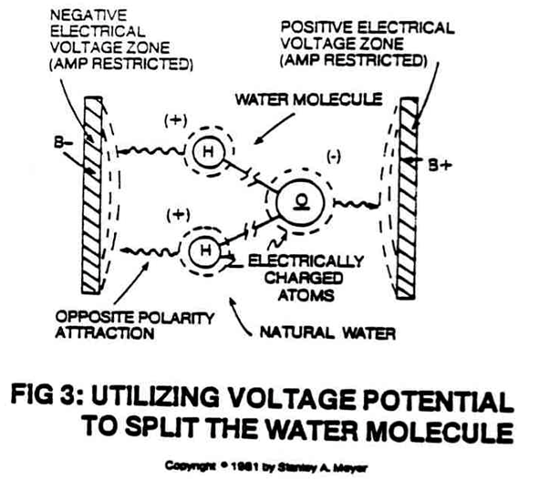
The positively charged hydrogen atoms are attracted to the negatively charged voltage zone, and the negatively charged oxygen atoms are attracted to the positively charged voltage zone...satisfying the opposite polarity attraction law of physics as shown in Figure 3.
ELECTRICAL POLARIZATION PROCESS:
Simply, the electrical polarization of the water molecule is basically a four-step process.
- First, oppositely charged electrical voltage zones are simultaneously introduced to either side of the water molecule.
- Secondly, the water molecule becomes electrically polarized (electrically charged).
- Thirdly, this electrical polarization of the hydrogen and oxygen atoms greatly weakens the stability of the water molecule.
- And, finally, because the-voltage zones are still present with their opposite electrical attractions, the water molecule is split into it component parts.
The hydrogen and oxygen atoms separate, with the hydrogen being attracted to the negative electrical voltage zone, while the oxygen is attracted to the positive electrical voltage zone…all simultaneously.
COVALENT BREAK-UP OF THE WATER MOLECULE:
In scientific terms, once the electrical polarization process occurs, the covalent bonding or sharing of electrons between atoms of the water molecule ceases to exist since the positive electrically charged hydrogen atoms attract the free floating negative charged electrons; while, at the same time, the negative electrically charged oxygen atom repels the moving electron...
- thereby stabilizing the energy level of the atoms...
- separating the water molecule into its component parts...
- releasing energy in the form of hydrogen gas and oxygen gas, as illustrated in Figure 3.
The opposite polarity attraction that now exists between the liberated electrically charged atoms and the stationary electrical voltage zones further aids the splitting process. The repetitive pulse voltage frequency potential, or reforming voltage zones, continue the electrical polarization process.
What is so dramatic about disassociation of the atoms in the water molecule is the ease at which the task is done. Because the bond between the hydrogen and oxygen is already greatly weakened by the electrical polarization of the water molecule, very little energy in the form of applied voltage is needed to actually separate the hydrogen and oxygen atoms. The hydrogen and oxygen atoms that make up the water molecule are already seeking to move in opposite directions because of their respective attractions to the opposite electrical voltage zones. A minute amount of voltage, a potential energy without amp consumption, gives the atoms the impetus to break away from one another in a strictly physical process. Hydrogen and oxygen gases are released in great amounts with little energy being consumed and without chemical interaction. Once the splitting of the molecule occurs, the liberated hydrogen and oxygen atoms will not recombine in the polarization process. Therefore, the gas can be utilized for energy consumption.
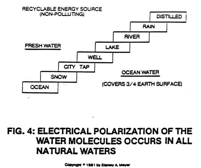
NATURAL WATER, THE SOURCE FOR HYDROGEN:
Under actual lab certification testing, it is shown that by utilizing pulse voltage frequency potential, splitting of the water molecule occurs in all natural water, even distilled water, as shown in Figure 4.
Operational Parameters of the Invention
THE FORMATION OF VOLTAGE ZONES:
After it was discovered that the hydrogen and oxygen atoms in natural water could be electrically charged, all that was needed was the creation of two electrical voltage zones, opposite in electrical polarity, placed on either side of the water molecule.
Simply by applying voltage potential, the oxygen atom, now with a negative (b-) electrical charge, is attracted to the positive (b+) electrical voltage zone.
Likewise, the hydrogen atoms, now with a positive (b+) electrical charge, are attracted to the negative (b-) electrical voltage zone.
In the repetition of this process, the water molecules are being split, releasing oxygen gas and energy in the form of hydrogen gas.
In order to capitalize on the electrical polarization of the water molecule and maximize the release of hydrogen energy, it is imperative that the process take place in a non-chemical environment.
Stressing that this is simply a physical process, only natural water is utilized without any additives or chemicals.
The voltage zones used are two non-oxidizing, non-corrosive, non-reactive, stainless steel exciter plates emerged in a non-chemical, non-reactive housing.
Voltage, or potential energy, flows across the exciter plates, one plate being positive (b+) electrically charged and one being negative (b-) electrically charged.
Voltage moves across the plates, but the flow of amps is restricted.
Since almost no amps flow across the zones, the process remains chemical free and energy consumption in the process is extremely low.
The electronic circuit interfacing determines how the amps are restricted.
Contaminants in natural water remain contaminants and have no effect upon the electrical polarization process.
VOLTAGE IS POTENTIAL ENERGY:
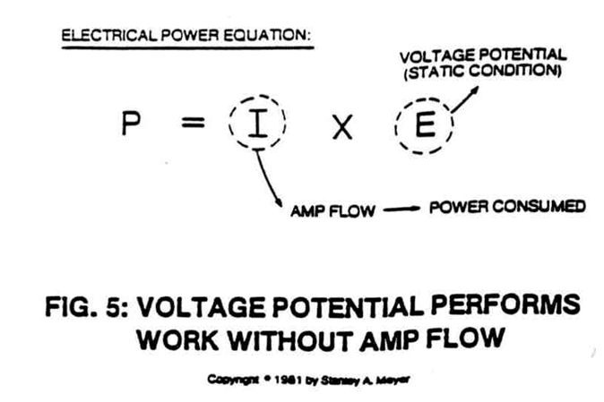 In the electrical energy equation Power = Amps X Voltage (see Figure 5), voltage becomes potential energy since the flow of amps is restricted across the plates.
Since the Fuel Cell uses voltage potential (remember, voltage is pressure or force within an electrical system called potential: unlike charges attract while like charges repel; voltage potential is used to electrically charge the atoms to disrupt the electron flow, covalent bonding, between the atoms) to economically split the water molecule, very little power is being used to release a terrific amount of energy.
The hydrogen being released is two and a half times more powerful than gasoline.
The Fuel Cell simply releases stored energy from natural water economically.
 |
 |
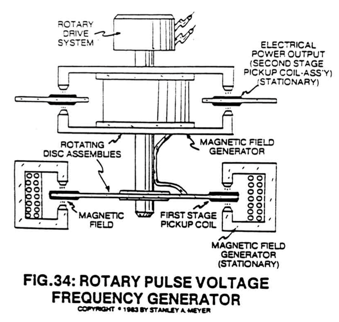 |
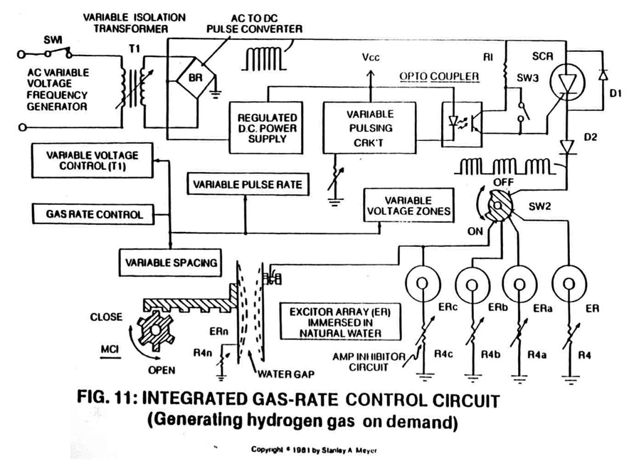
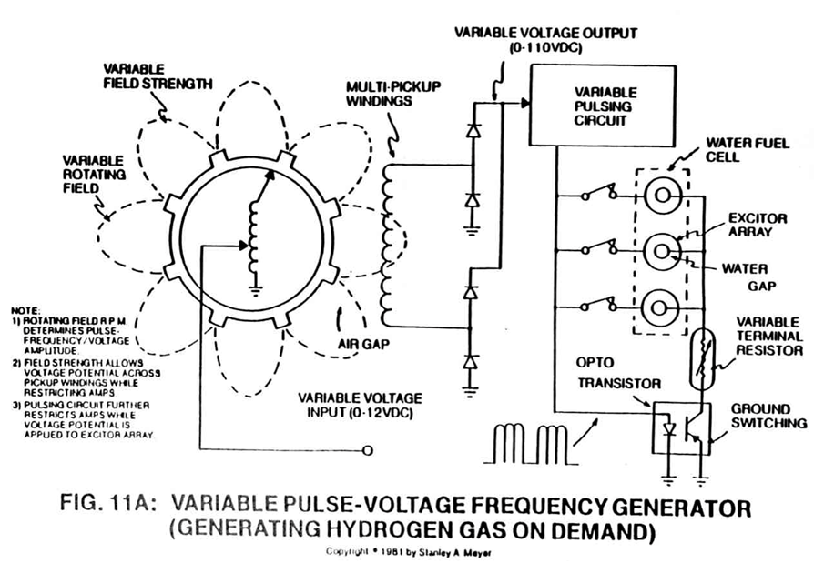
The pulse voltage frequency generators, as shown in Figures 11, 11A, and 34, are relatively small in comparison to a conventional amp generator.
The low-cost features of the Fuel Cell make the system ideal for utilization: it uses free water, simply does not decompose during operations, and uses voltage potential that is not consumed during hydrogen gas production.
These economic features of the Fuel Cell now establish natural water as a new, free, and abundant energy source.
After all, three-fourths of the earth's surface is covered with water...of which two thirds by atomic weight is hydrogen gas. Furthermore, using natural water requires no refining process, no distribution network, nor special packaging.
PRODUCING HYDROGEN ON DEMAND:
 Until now, voltage potential has been used in two ways to operate the fuel cell: electrically charging the atoms of the water molecule to disrupt covalent bonding of the water molecule and to separate the liberated atoms for utilization.
Another aspect is to attenuate the voltage potential to generate hydrogen gas on demand. This is simply done by manipulating the parameters of the voltage zones.
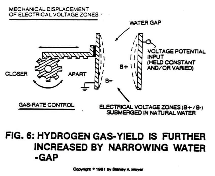
One technique to control gas production is to physically move the voltage zones, or plates, closer together, while keeping the voltage potential constant, as illustrated in Figure 6.
Moving the voltage zones closer together causes a greater electrical force to be applied to the electrical polarization process…causing hydrogen to be produced exponentially.
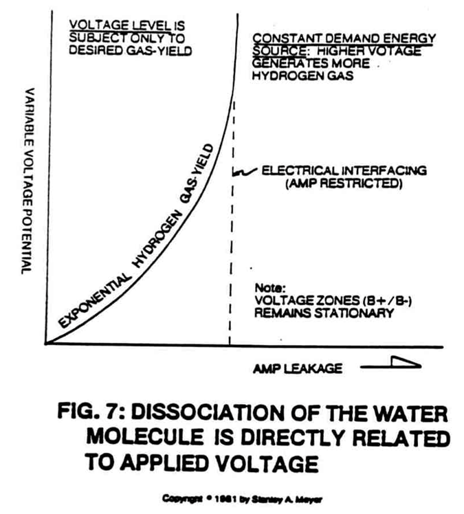
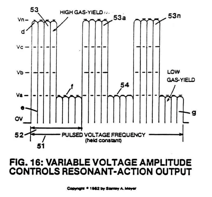
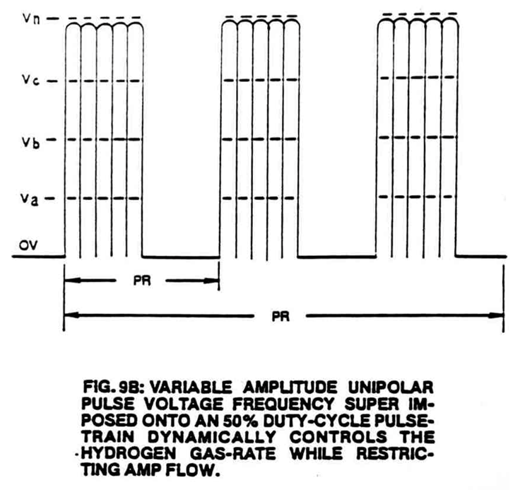
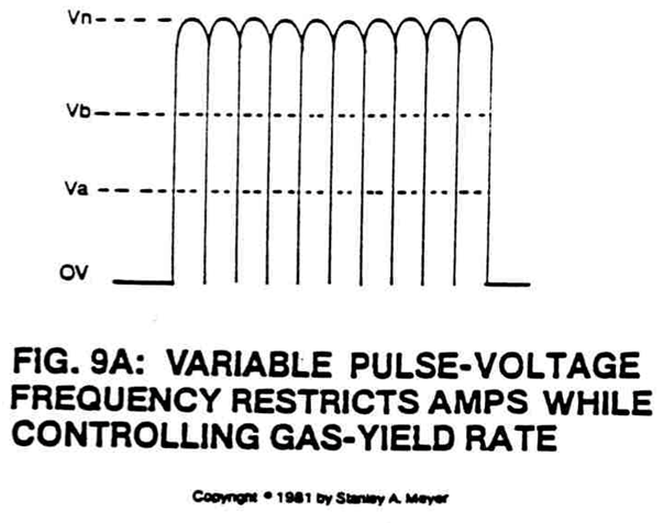
Another way to control the hydrogen gas production is to maintain the electrical voltage zones in a fixed position, and increase the intensity of the electrical voltage potential (see Figures 9A, 9B and 16...Va, Vb, Vn) across the zones, as illustrated in Figure 7.
 |
 |
 |
Again, hydrogen gas is produced exponentially as voltage potential increases.
The pulse voltage frequency potential is used to help restrict amp flow during the electrical polarization process.
Voltage potential may be increased to any desired level to meet hydrogen gas production on demand.
Zero to 20,000 volts range is quite normal at any frequency level.
Also, gas production is greatly manipulated by changing the physical design characteristics of the voltage zones (voltage zones taking on the shape of the exciter plate...skin effect).
 |
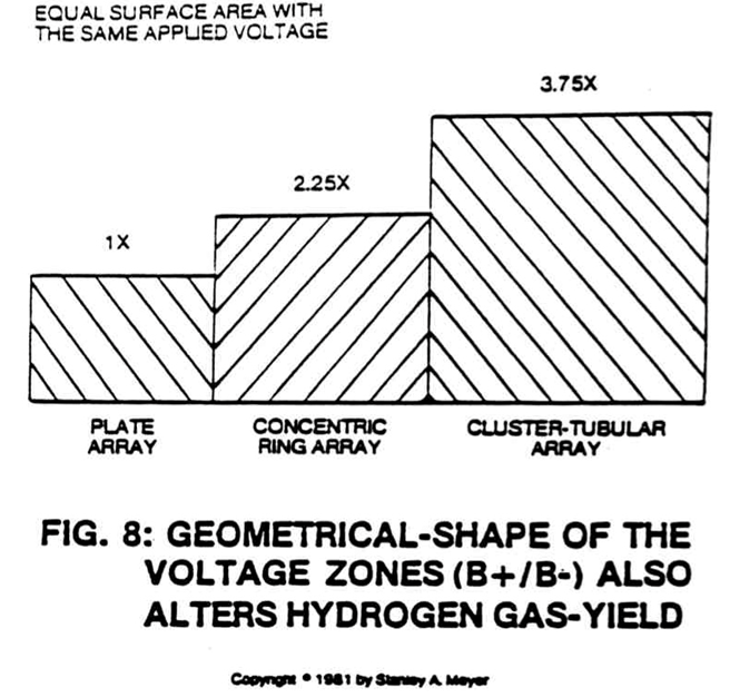 |
This includes increasing the size (height or width or diameter) of the zones, and/or the shape and configuration of the zones, as shown in Figure 8.
Finally, gas production is greatly manipulated by simply switching on and off, or pulsing, the electrical voltage zones in a variable, repetitive manner, as shown in Figures 9A, 9B and Figure 16.
The higher the frequency of the voltage pulse the greater the production of gas.
|
|
|
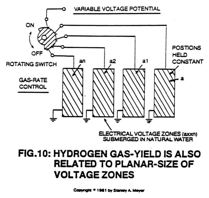 Coupled with this voltage pulsing is "segmentation."
The voltage zones may actually be segmented, with areas of the zones physically removed at a given point, as illustrated in Figure 10.
This reduces gas production.
When the segments are reintroduced inside the Fuel Cell, gas production increases.
By combining these voltage potential parameters into a functional control system, as shown in Figures 11, 11A and 34, the Fuel Cell now becomes a constant demand generator.
As energy is needed, simply vary the voltage potential parameters to meet the need.
|
|
|
The Fuel Cell, therefore, needs no secondary storage system since hydrogen is being stored in the safest storage medium known to man until used...water. Can you not use water to extinguish a fire?
Mega Watt Gas Yield
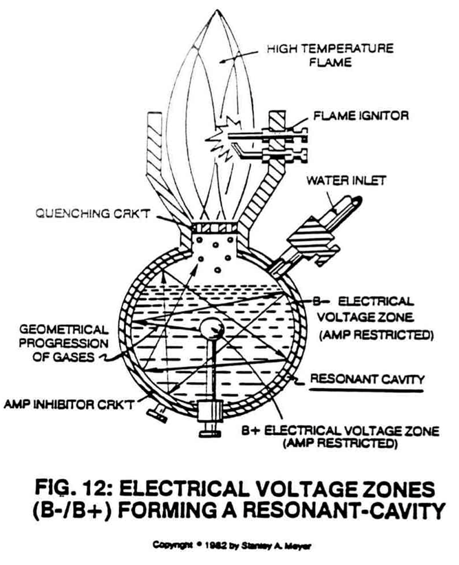
The previous method of producing hydrogen gas via the application of voltage potential (pressure or force within an electrical system) is quite efficient, but there are several advance steps to the ELECTRICAL POLARIZATION PROCESS that increase hydrogen gas energy production astronomically from natural water.
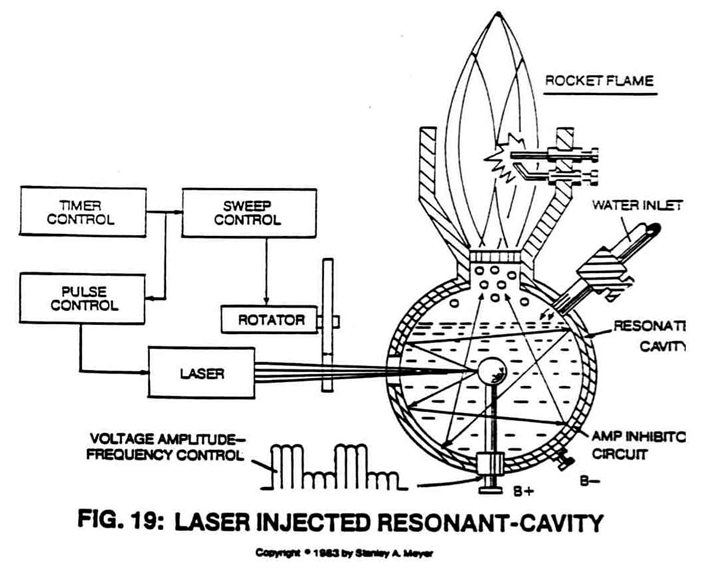
This is simply done through the use of a Resonant Cavity Fuel Cell, as so illustrated in Figures 12, 17, 19 and 20.
 |
 |
|
|
|


RESONANT ACTION AND THE PHENOMENA:
The Resonant Action (as graphically depicted) within the Fuel Cell occurs in a systematic way.
First an oscillating voltage field, or zone, is formed around a second oscillating voltage field, or zone, opposite in electrical polarity and forming a water zone in between.
The two oscillating voltage zones are synchronized into a single repetitive wave form as shown in Figures 9A, 9B and 16.
|
|
 |
As the water molecules are exposed to the reforming voltage zones, the hydrogen atoms become positive electrically charged while the oxygen atom becomes negative electrically charged...electrically polarizing the water molecule, as illustrated in Figures 2 and 3.
|
|
|

The pulsating voltage zones also help restrict amp flow during the electrical polarization process.
Once the electrical polarization phenomenon occurs, the covalent bonding, or sharing, of electrons between atoms of the water molecule ceases to exist since the positive electrically charged hydrogen atoms attract the free floating negative charged electrons while, at the same time the negative electrically charged oxygen atom repels the moving electrons...
- thereby stabilizing the energy levels of the atoms...
- separating the water molecule into its component parts...
- releasing energy in the form of hydrogen gas and oxygen gas, as illustrated in Figure 3.
The opposite polarity attraction that now exists between the liberated electrically charged atoms and the stationary electrical voltage zones further aids the splitting process by imparting a physical impact (particle impact) on neighboring molecules undergoing the electrical polarization process.
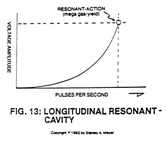
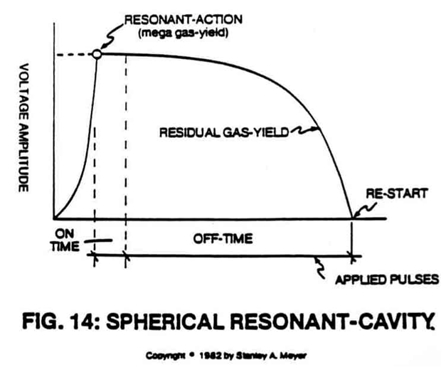
Since the voltage zone that forms the resonant cavity outer wall momentarily entraps the liberated atoms, the moving atoms are accelerated and deflected among other molecules being split...causing compound action, as so illustrated in Figures 13, 14 and 15.
 |
 |
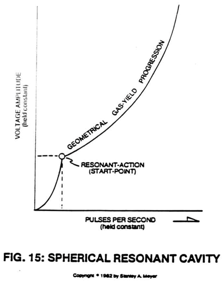
This compounding action continues to increase as more atoms are being liberated from other water molecules.
The repetitive pulse voltage frequency potential continues the compounding action, whereas an increase in voltage amplitude speeds up the compounding action under controlled means.
Simply moving liberated atoms back and forth uniformly through the electrical polarization process in a repetitive manner establishes Resonant Action within the Fuel Cell.
RESONANT ACTION ENHANCEMENT:
 Resonant Action enhancement beyond the influence of pulse voltage potential is accomplished in several ways. In the area of electron deflection, the electrically charged atoms moving toward the water molecules further disrupt the covalent bonding, while at the same time increasing the electrical charges inside the Fuel Cell during the electrical polarization process.
Increasing the number of electrically charged atoms within the Fuel Cell directly increases the voltage charges within the same cell while applied pulse voltage frequency potential remains the same...increasing gas yield while power input remains constant.
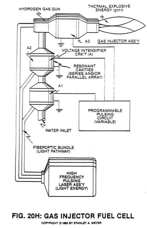
In terms of design application, the resonant cavity is multi-tier with other resonant cavities of similar design in a sequential manner, as shown in Figures 20D, 20H, and Figure B.
As the electrical polarization process occurs, the liberated and electrically charged atoms are recycled inside the resonant cavity prior to atom injection into the next cavity-structure undergoing the same recycling process.
|
|
|
The orderly and sequential progression of the moving charged atoms through the cavity-array increases the voltage charges per stage since more atoms are being allowed to interact with each proceeding stage.
To increase gas yield even further, additional atom recycling cavities are affixed to the vertical array to meet a predetermined gas need.
The interaction of the laser beam or light energy (see Figure 20D) with the liberated atoms inside the resonant cavity during the electrical polarization process causes the free floating atoms to either lose or gain electrons...causing said atoms to become electrically charged and used as herein described.
The expelling charged atoms of Figure 20D are used in conjunction with the electrical polarization generator of Figure 40 to form the regenerative energy feedback network of Figure A as pictorially illustrated in Figure B.
This process simply uses the component parts of water to produce electricity without consuming the charged atoms prior to gas ignition.
 |
 |
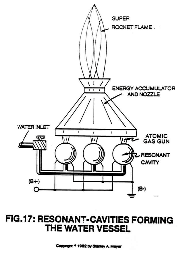
ATOM INJECTED RESONANT ACTION: THE ROCKET ENGINE:

To capitalize on this electrical charge phenomena still further, the atom-injected resonant cavity of Figure 20 was developed.
The atom guns are smaller resonant cavities that liberate and expand electrically charged hydrogen and oxygen atoms into accelerator tubes for particle acceleration.
Once accelerated to maximum speed, the projected electrically charged atoms are injected into a larger resonant cavity...providing particle impact…supercharging the electrical field inside the central fuel cell for even higher gas yield.
This electrical charging process is ideal since natural water is the prime source for the electrically charged atoms.
This process is further exemplified in the vertical-array fuel cell of Figure 20H and power loading circuit of Figure 20D.
|
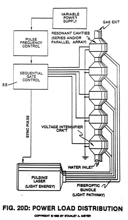 |
Note how the high voltage pulse is sequentially sync with the pulsing laser during each cavity stage.
LASER INJECTED RESONANT ACTION: THE THROTTLE BOOSTER:
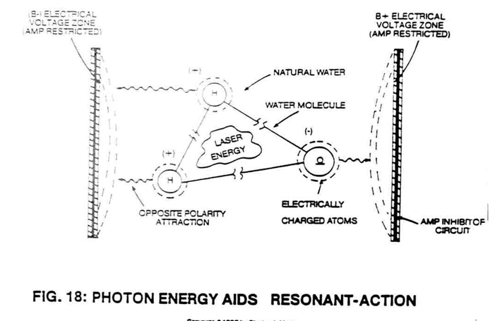
Since laser or light energy is electromagnetic energy having zero mass and no electric charge, particle impact within said resonant cavities is accomplished by ionizing the atoms of said water molecule.
As the laser energy is superimposed onto the electrical polarization process, as shown in Figure 18 and 19, the photon or light energy (see Figure 19A) is being absorbed by the water molecule atom(s) nuclei.
 |
 |
Once the electrical polarization process occurs, many liberated atoms (including ambient air gases) become positive electrically charged when said atoms lose an electron, forming a positive charged ion.
The electromagnetically primed (atom absorbing light energy) hydrogen atom may now accept said liberated electron, forming a negatively charged ion.
By simply attenuating said high intensity voltage pulse, said charged atoms are set into motion…causing particle impact or particular collision during the electrical polarization process.
The liberated negatively charged electrons are also set into motion to help aid or boost said particular impact.
The uniform movement (particular oscillation) of said electrically charged particles within said resonant cavity is now called compounding-action or resonant-action.
Hydrogen Gas Gun Technology:
To sustain energy-yield beyond the gas-flame combustion state sustaining and maintaining a hydrogen/oxygen flame), the Electrically charged (atom having missing or more than normal amount of electrons) and "Optically Primed" (atoms absorbing photon energy) combustible gas ions being expelled from Resonant Cavity Array (Figure 20D) now enters into and through a Hydrogen Gas Gun Assembly placed on top of and interlocked with said Resonant Cavity Assembly, as illustrate in Figure 20H.
|
|
The moving combustible gas ions are subjected to higher energy levels (Voltage and Laser Stimulation) while being exposed to an Electron Extraction Process for the purpose of further destabilizing the mass/electrical equilibrium of said gas atoms.
The Voltage intensifier Circuit simply prevents electron replacement during voltage stimulation.
 The specially treated combustible gas ions are now subjected to thermal stimulation via an Optical Thermal Lens Assembly...forcing said Electrically Charged and Laser Primed combustible gas ions to reach critical state...
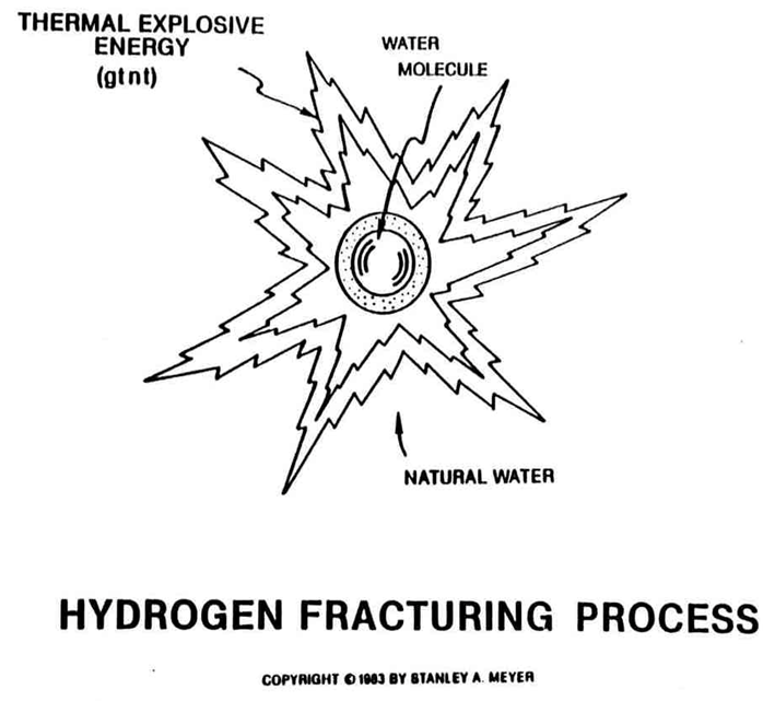
causing said gas ions to decay...releasing thermal explosive energy beyond the gas flame stage.
The point of atomic energy-yield is simply reached when the electron deficient oxygen atom (having less than normal amount of electrons) locks onto and captures the hydrogen atom electrons prior to and during thermal-combustion stimulation.
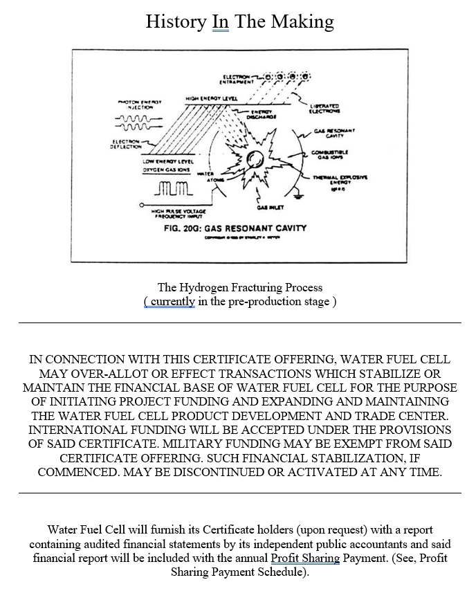
The thermal explosive energy-yield is known as the "Hydrogen Fracturing Process."
Together, the Optical Thermal Lens Nozzle, the Hydrogen Gas Gun, and Resonant Cavity Assembly forms a design variable Water Fuel Cell that is cost effective as to retrofit energy systems.
Fuel Cell Economics
DESIGN TO RETROFIT:
 Due to the discovery of the electrical charging of the water molecule and the use of voltage zones for splitting water into hydrogen and oxygen, the Fuel Cell is easily adaptable to all types of energy needs.
Not only that, but the Water Fuel Cell is a retrofit system that does not require drastic changes in the energy consuming device.
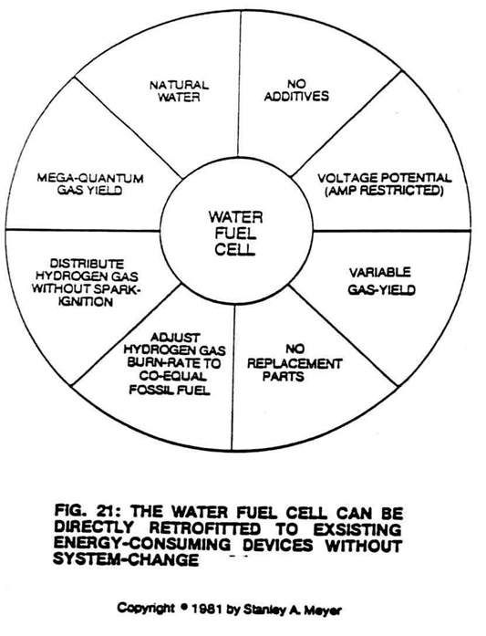
The simple, yet staggering design of the Fuel Cell lends itself to many other advantages over traditional energy sources; see Figure 21.
A PHYSICAL PROCESS:
Since voltage, a potential energy, is used for the electrical polarity zones, the entire process of splitting the water molecule is a physical one.
Amps are restricted in the electrical polarization process, so there is almost no chemical reaction in the environment of the Fuel Cell.
Since chemical interaction is not required during the electrical polarization process, any form of natural water may be used for the extraction of hydrogen as fuel.
Rain water, well water, tap water, river water, reservoir water, snow, distilled water, and even ocean water may be used in the Fuel Cell.
Salt water has no adverse effect upon the Fuel Cell because amps are restricted. Salt and other minerals in the water are contaminants that are simply discarded.
They do not disrupt the normal function of the Fuel Cell. So, how cheap is water?
HYDROGEN: MORE POWERFUL THAN FOSSIL FUELS:
Due to the inherent properties of the Water Fuel Cell, a little energy is being consumed to release a tremendous amount of energy in the form of hydrogen gas in the form of hydrogen for use as fuel.
By atomic weight (NASA test data), hydrogen is two and a half times more powerful than gasoline.
Two thirds of a gallon of water contains hydrogen. So, how powerful is water?
WHAT'S THE COST OF WATER?:
There are no expensive forms of chemical additives that have to be mixed to the water for hydrogen production.
You do not have to process the natural water in any fashion.
WHAT'S THE COST OF VOLTAGE?:
The system is a voltage device, not an amp device.
Voltage is a potential energy, not a consumed energy.
Because of this, there is almost no consumption of power to split the water molecule into its component parts.
The cost of voltage is negligible when amps are restricted.
Simply by varying the voltage to the system, or the physical parameters of the system, production of gas will increase exponentially. But, energy consumption does not increase, even if voltage is increased.
FUEL CELL LONGEVITY:
Since the Fuel Cell is a non-chemical device, the use of non-oxidizing, non-reactive, non-corrosive materials provides for a system that has an extremely long life (lab tested .0001/yr) and does not need replacement parts.
The system will not self destruct during gas Production.
FUEL CELL MEETS THE NEED:
Because of its operational properties, the Fuel Cell may take on any form or size.
The flexibility of design allows for use in any application.
The pulse voltage frequency generator applied to the Fuel Cell is very small in comparison to traditional on-site power generators.
A large generator is simply not needed when voltage is only being used.
Because the Fuel Cell may take on any geometrical configuration and the pulse voltage generator is design-flexible, the energy source may be retrofitted to any energy-consuming devices. Simply adjust the size to meet the need.
OTHER FUEL CELL FEATURES:
The Fuel Cell takes advantage of existing manufacturing technology and standard material for construction.
There is no need to design new electronic components or develop exotic materials to implement the Fuel Cell into the marketplace.
The cost of the Fuel Cell is extremely low as compared to the cost of using conventional energy sources.
Water is simply free energy without any overhead refining cost or packaging expense.
Water is simply reclaimed and recycled when the hydrogen energy is used in the form of heat.
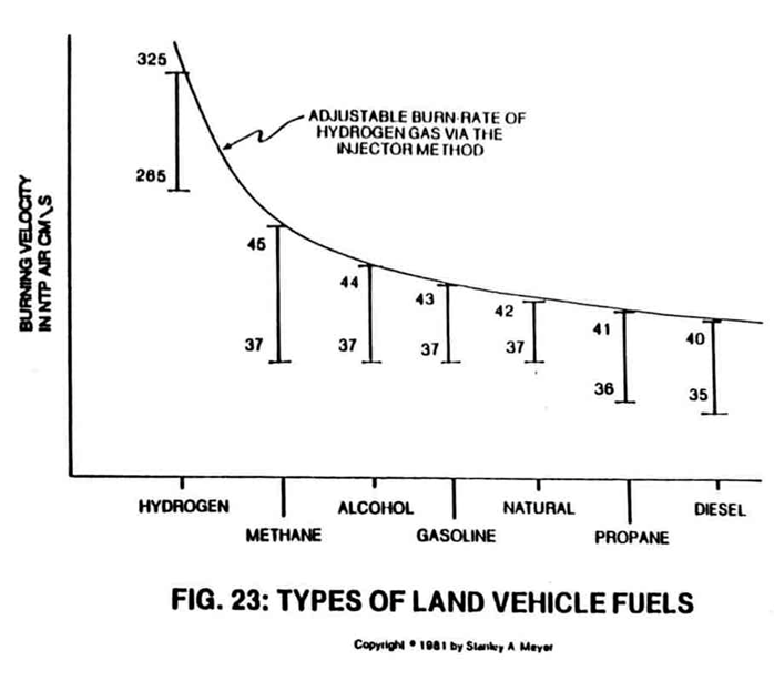
There is no additional cost involved when adjusting the hydrogen burn rate to co-equal fossil fuels (see Figures 23 and 24) since the Fuel Cell utilizes natural water as the gas-mixing regulator.
 |
 |
The gas mixture remains the same regardless of the gas rate of the generator.
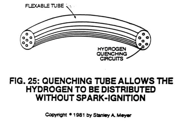 The same gas mixture derived from natural water is also used without added cost to prevent spark-back into the Fuel Cell and distribution lines, as illustrated in Figure 25.
In conclusion, the Fuel Cell simply produces and renders hydrogen gas safer than natural gas without any additional cost beyond the cost of voltage.
Remember, water is free.
Hydrogen Gas Utilization
THE NEED TO RENDER HYDROGEN SAFE:
Not only can the Fuel-Cell economically produce. a huge amount of hydrogen gas on demand, it can also adjust the burn rate of the hydrogen gas to co-equal the burn rate of fossil fuels without additive chemicals.
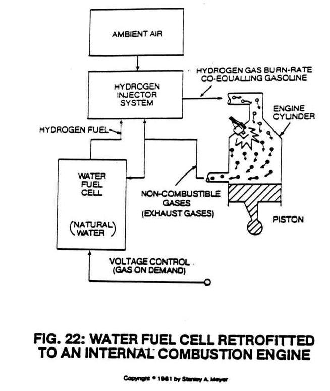
For example, to run a typical automobile on hydrogen gas without altering the engine or performance, the hydrogen gas is automatically adjusted to co-equal the burn rate of gasoline or diesel fuel, as shown in Figures 22 and 23.
 |
 |
The Fuel Cell can also duplicate the burn rate of natural gas or other burnable fuels now being used in the marketplace.
The Fuel Cell simply has the ability to safely and effectively render hydrogen as a useful fuel and does it economically. It also means that the Fuel Cell can be retrofitted to any type of existing power system using gas fuel.
QUENCHING CIRCUIT: ANTI SPARK-BACK:
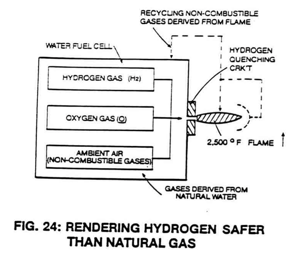
The Fuel Cell accomplishes this by using a hydrogen quenching circuit (see Figure 24) with the use of natural water.
This small, button-sized circuit allows for the adjusting of the burn rate to support a sustained hydrogen-oxygen flame well over 2,500 degrees Fahrenheit without any spark-back into the Fuel Cell.
It also helps keep the gases uniformly mixed inside the Fuel Cell during gas production.
SUSTAINED HYDROGEN FLAME ON DEMAND:
During the splitting of the water molecule, ambient air supplied by the water and having gases that do not support combustion passes through the very small quenching circuit with the hydrogen and oxygen gases prior to flame combustion.
The non-combustible gases act as a modulator that reduces the speed at which the oxygen atom unites with the hydrogen atom to cause flame combustion.
More specifically, the non-combustible gases associated with ambient air entrapped in natural water act as a dilutant that allows the hydrogen to burn at a rate equal to fossil fuels.
The water itself acts as a gas-mixing regulator where the gas-mixing ratio remains constant regardless of the rate of gas production.
Again, no costly manufacturing process is needed to convert hydrogen to fossil fuel burning levels.
If for some reason you need a flame temperature greater than 2,500 degrees F., simply reduce the amount of non-combustible gases being mixed with the hydrogen.
If you need the flame temperature to be lowered, simply recycle the expelled flame gases (ambient air gases exposed to the sustained hydrogen flame) back into the burning process.
These gases further dilute the hydrogen burn rate.
However, gas production is still dictated by demand, and mixing rate maintained regardless-of the rate of gas generation.
The hydrogen flame is sustained and maintained at all times during Fuel Cell operations.
HYDROGEN AS A CLEAR BURNING FUEL:
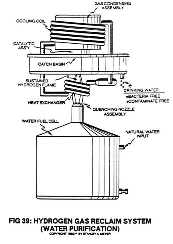 The by-product of burning hydrogen and oxygen is simply water mist when the Fuel Cell utilizes a specially designed catalytic block that ensures almost one hundred percent conversion of the Fuel Cell burnable gases.
The catalytic block, as used in the hydrogen reclaim system of Figure 39, accomplishes this gas conversion process in a systematic way.
First, the catalytic block entraps all combustible gases (gases expelled from the flame) that have not undergone the flame burning process of combustion.
The catalytic block re-exposes the escaped an entrapped burnable oases to the sustained hydrogen flame for gas combustion...eliminating any and all unused hydrogen and oxygen atoms...by combining these free-floating atoms to form water vapor when ignited.
This second stage burning process superheats the catalytic block to further aid the combustion process.
Once the oxygen and hydrogen atoms are completely locked into the water molecule formation, the atoms are consumed and cannot unite with other ambient air gases.
For example, Nitrous Oxide (N20) cannot form since there are no oxygen atoms available to unite with the non-combustible nitrogen gas to form an oxide gas.
Likewise, Nitrous Acid (HNO2) in solution cannot form since there are no hydrogen atoms available to unite with nitrogen and oxygen atoms to form an acid in solution.
Remember, there are no oxygen atoms present to help form the acid base.
The catalytic block simply renders the Fuel Cell environmentally safe.
This simply means that the water vapor produce from the Fuel Cell can be recycled back into the atmosphere to form rain which can be collected again for hydrogen gas reuse.
Of course, this recycling method is not as efficient as the hydrogen gas reclaim system of Figure 39, and so, illustrated in Figure A.
QUENCHING TUBE: DISTRIBUTING HYDROGEN SAFELY:
To transport hydrogen gas from the Water Fuel Cell without spark ignition, the quencher circuit is carried one step further. Transportation of hydrogen--- is done without regard for distance, through the "quenching tube" see Figure 25.
As the hydrogen passes through the tube, ignition cannot occur because it is impossible for the hydrogen, oxygen, and non-combustible gases to unite within the small confines of what is essentially an elongated quenching circuit.
Gas pressure is not a factor either.
If the gas pressure from the Fuel Cell decreases or is somehow shut off, the hydrogen still cannot retrace its path with the oxygen to unite for combustion.
FUEL CELL MEETS SAFETY REQUIREMENTS:
The Fuel Cell is basically a composite of many systems integrated into a functional system.
The system is one of constant demand that stores hydrogen in water until used.
Water is the safest storage medium known to man.
The hydrogen burn rate is adjusted to co-equal that of fossil fuels by using the quenching circuit and recycling of non-combustible gases back into the system.
This allows hydrogen gas to be used in place of natural gas.
The hydrogen gas can be transported without spark ignition, thanks to the quenching tube.
The burning of the hydrogen gas is rendered clean by the catalytic process.
And finally, hydrogen recycling is performed for energy reuse.
These integrated features give the Fuel Cell the ability to comply with and supersede any and all federal, state, and local housing and/or highway safety regulations.
Dynamic Ways To Produce Electricity
WATER, THE SOURCE FOR ELECTRICITY:
The previous sections have outlined how hydrogen may be safely, easily and economically extracted from natural water.
Not only that, the previous pages have shown how hydrogen may be harnessed for use as a free and abundant fuel source.
Also, it has been shown how the hydrogen may support a flame in excess of 2,500 degrees Fahrenheit to supply thermal energy.
But, in practical terms, how can this hydrogen energy from natural water be used to create electricity for use in factories, homes and businesses?
This may be done in several ways.
LIMITS PLACED ON CONVENTIONAL POWER SYSTEMS:
Currently, there are several ways to use high temperature flames to produce electrical energy.
First, high temperatures may be used to power gas-actuated electrical generators.
The high flame heats the gas, which becomes the driving force to power the generator, which in turn creates the electricity for use.
Similarly, heat may be used to create steam to drive generators for electrical production.
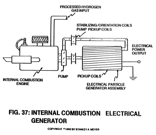
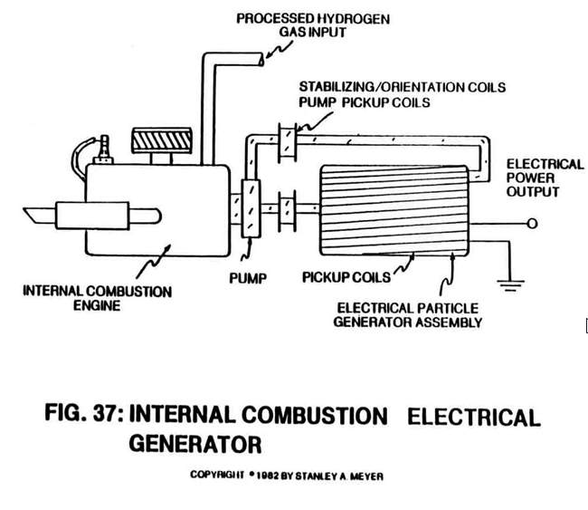
Or, the hydrogen burn rate may be adjusted to co-equal the burn rate of fossil fuels (as previously described) to operate a gas-driven (internal combustion engine) electrical generator.
The gas-driven engine not only provides mechanical to turn the electrical generator, but also manufactures the exhaust gases needed to process the hydrogen gas on demand.
This feedback technique is extremely good since the gas engine requires no special cooling apparatus nor the use of special high temperature alloys or materials for construction.
What does this mean for the consumer?
Remembering that hydrogen by atomic weight is more than two and a half times more powerful than gasoline (NASA test data), and that 2/3rds of a water molecule contains hydrogen, not more than six gallons of water is needed to heat or cool an average 2,000 square foot home (rated at 135,000 per degree day) in a 24-hour period.
Several additional gallons of water are all that is needed to provide home electricity during the same time period.
Also, a few gallons of water is all that is needed to run a typical passenger car in excess of 55 miles per hour.
All the systems may utilize the hydrogen by adjusting the burn-rate downward without sacrificing power yield.
All systems have the capability to recycle hydrogen back into the form of water for energy reuse. See Figure A.
All of the above gas-driven systems are efficient and adequate, and all have common characteristics.
They all have mechanical displacement parts that result in component wear during application.
This may lead to higher operating costs because the lifespan of some mechanical parts may be limited.
In order to provide an even more efficient and reliable energy system that complies with the laws of economics (the person with the least expensive way will be successful).
Meyer has discovered how to create electrical energy without the need for moving mechanical parts.
THE BIRTH OF NEW TECHNOLOGY: THE EPG SYSTEMS:
Meyer has done this by developing the "Electrical Particle Generator” (EPG system).
He contemplated the idea of how to create a device with no mechanical moving parts that could produce electrical energy in all applications.
In order to do this, he knew he had to solve a multiplicity of problems.
He needed to develop a system that conformed to his development specifications for the Fuel Cell.
These specifications would allow the device to be constructed easily and economically, without the aid of hi-tech manufacturing techniques.
He also knew he must make the system reliable, durable and efficient.
He knew he also had to overcome the opposing magnetic field problem that requires high torque (rotational force) power input to operate conventional rotary electrical generators.
EPG: PRINCIPLES OF OPERABILITY:
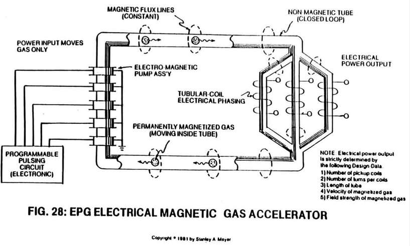
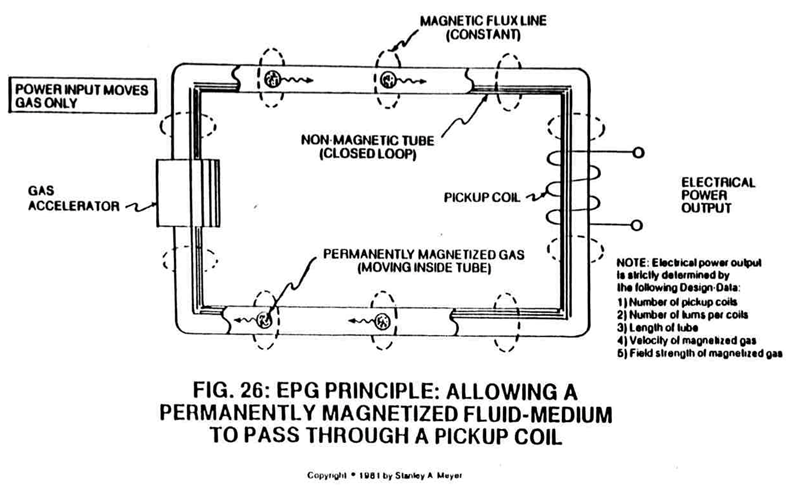
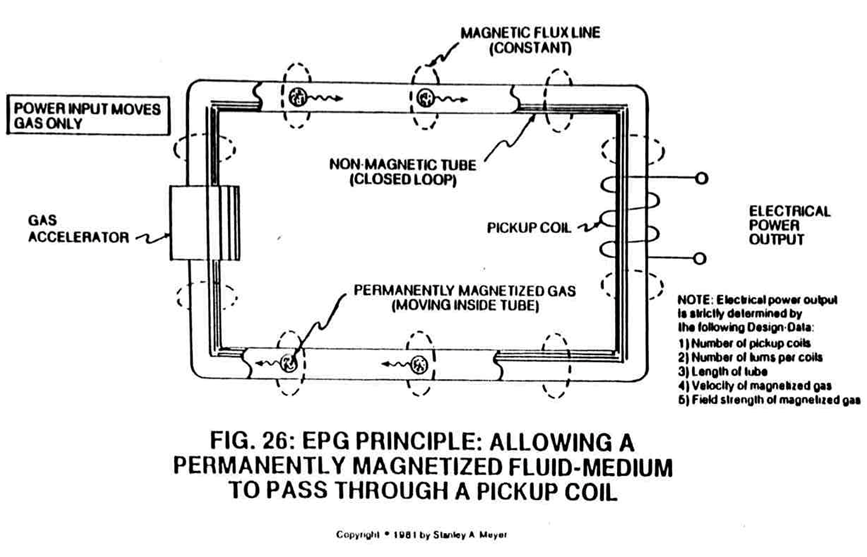 He accomplished the task with the Electrical Particle Generator by moving permanently magnetized gas through a non-magnetic, closed looped, tabular system; see Figure 26.
As it moves, this magnetically charged gas traverses a pickup coil, which generates electrical energy.
This process satisfies the law of physics that states that a magnetic field must pass through a coil of wire for the production of electricity.
Now, the permanently magnetized gas (which actually may be a fluid medium or semi-solid slurry) passes through the closed looped system without interruption.
The energy input into the electrical particle generator is to move the gas, not to create the magnetic field of the gas.
Since the moving gas field is attenuated to minimize the opposing EMF fields of the pickup coils, very little input energy is required to move the magnetized gas.
Power output from the electrical particle generator is simply determined by the coil-wrap of the tube through a given number of coils.
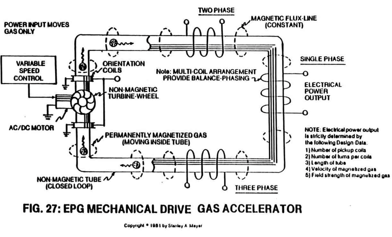
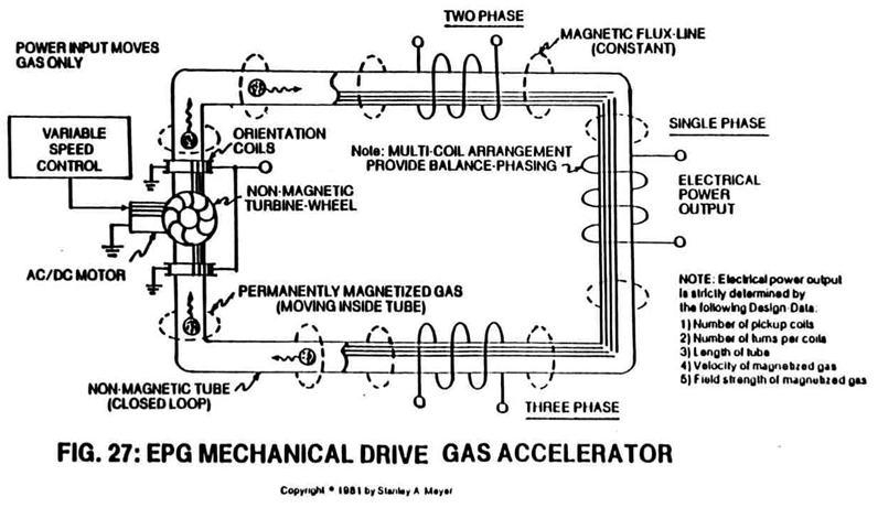
EPG: MECHANICAL DRIVE SYSTEM:
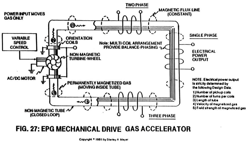 Only a few pounds of pressure is needed to drive the magnetically charged gas through the system.
This may be done mechanically by a small, non-magnetic turbine wheel powered by a small AC or DC electric motor; see Figure 27; or powered by hydraulics, steam, wind power, or even manpower.
But again, moving parts wear out, so this is the least desirable method of moving the gas through the system, despite the fact input to output efficiency of the electrical particle generators exceeds the performance "specs" of typical rotary electrical generators.
EPG: ELECTROMAGNETIC DRIVE SYSTEM:
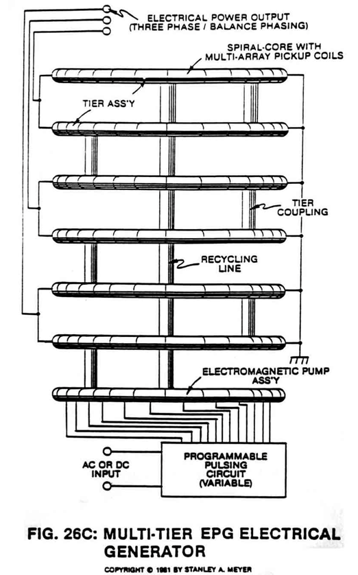
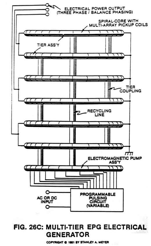
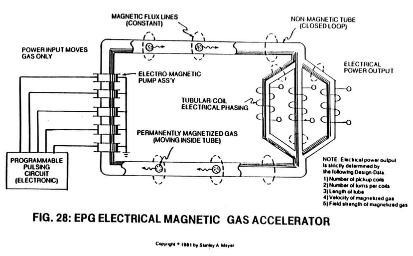
Another way to move the magnetically charged gas through the closed looped system is the use of an Electromagnetic Pump Assembly, as shown in Figure 26C and 28.
The multi-coil arrangement is pulsed in a way as to allow the electromagnetic field to "walk" in a linear motion.
Since the walking fields lock onto the gas, the gas moves onward to and through the pickup coils and is recycled again for continuous power generation.
Increasing pulsing rate increases gas velocity which, in turn, increases power output without system change.
 |
 |
EPG: PARTICLE BEAM ACCELERATORS:
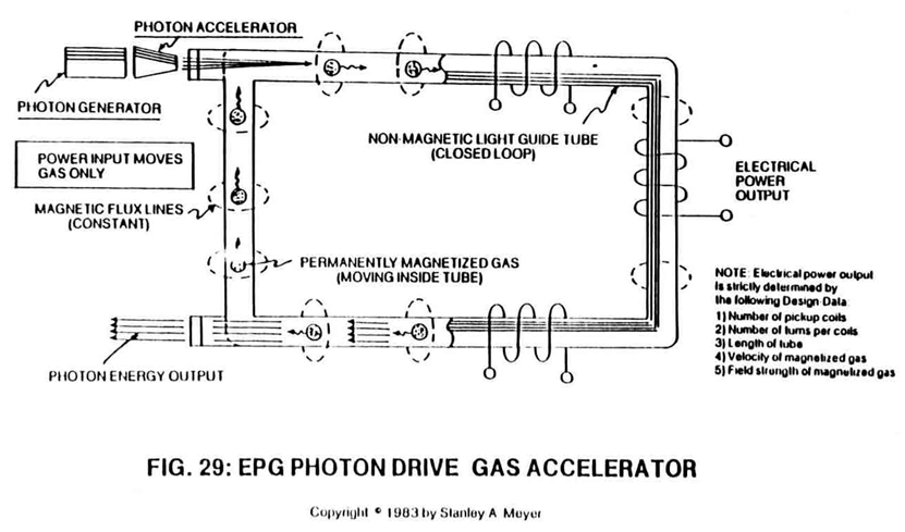 Finally, and most dynamic, is the use of a laser team driven EPG system; see Figure 29.
In this system, the permanently charged particles of gas are driven close to the speed of light through the closed looped system by the physical motion of the low power laser beam.
In this application, the non-magnetic tube is used as a typical light-guide (reflective surface inside a hollow tube).
In other applications, particle beam accelerators beyond the laser can be used for gas displacement...moving the gas-field for electrical power generation.
 EPG: ATTENUATING GAS—FIELD:
In each progression of the above cases, there is an increase in power output because the movement of the gas through the system is greater.
In each case, low energy is required to move the gas through the tubular system.
Because of the flexibility of the system design, it is the geometrical configuration of the system that determines power output.
In all cases, power input deals with moving the gas...not creating an electromagnetic field for the gas.
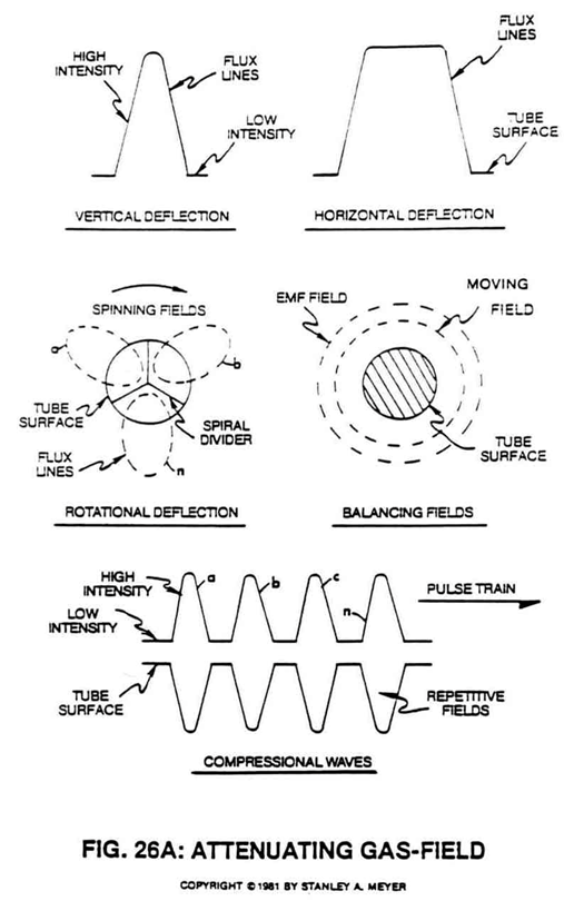
In all cases, the field of the gas can be attenuated in ways to overcome EMF opposition: horizontal to vertical deflection, rotational, compressional wave, and/or field balancing between different magnetic fields, as shown in Figure 26A.
Any combination of these attenuated fields can be used simultaneously while moving the magnetized gas.
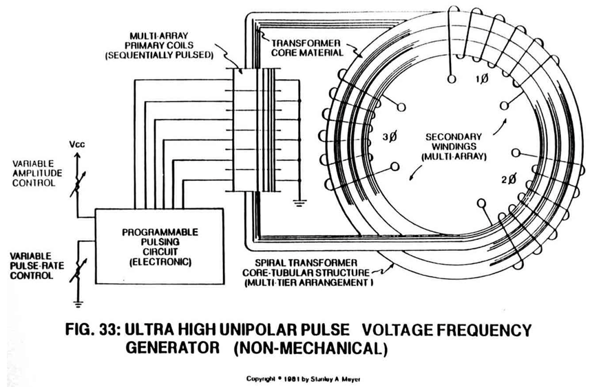
To spin the moving gas along the longitudinal axis of the tube without mechanical displacement, a multi-channel “spiral divider” (see Figure 26A) is inserted into the entire length of the tubular "pathway" (see Figure 33) beyond the gas accelerator stage, as illustrated in Figures 26 through 29.
|
|
|
|
|
|
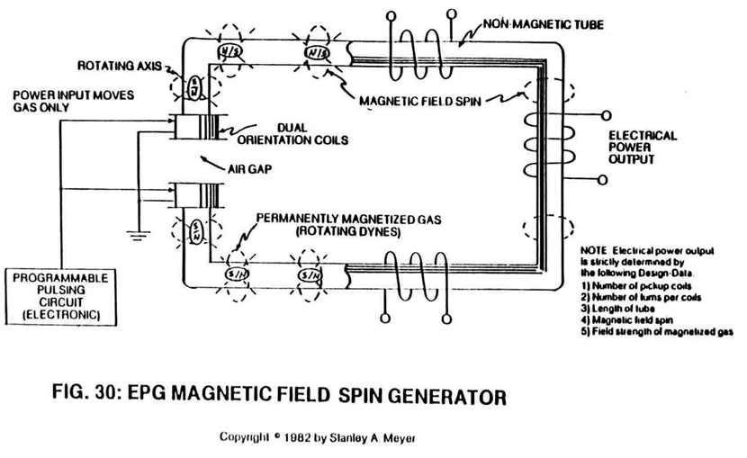
The rotating gas-field can now be varied from a vertical to horizontal movement (magnetic field cycling) by disrupting the dyne-axis (particle alignment) of the permanently magnetized gas (see Figure 30) when orientation coils (see Figures 27, 37 and 38) are used.
 |
 |
Pulsing the orientation coils slowly produces the horizontal movement of the gas-field, whereas a faster pulse rate creates a spike wave form.
The pulsating magnetic fields of the orientation coils simply regulate the particle spin of the gas in a linear motion since "transformer action" cannot occur due to the permanently magnetized gas.
 |
 |
A compressional wave form (Figure 26A) is now produced by superimposing a pulsating pressure onto the spinning gas.
Compounding action (clustering magnetic fields) of the wave forms occurs when the tubular "pathway" (see Figures 26B and 33) is spiraled through the pickup windings.
 |
|

And to help minimize wave form distortion, the EMF field strength is preset (balancing the fields) as to power loading of pickup coils.
These operational parameters help keep the gas velocity constant since the pulsating gas-field can be synchronized with the repetitive formation of the EMF field.
Of course, the oscillating magnetic fields (moving flux lines) transverse the coil windings for electrical power generation.
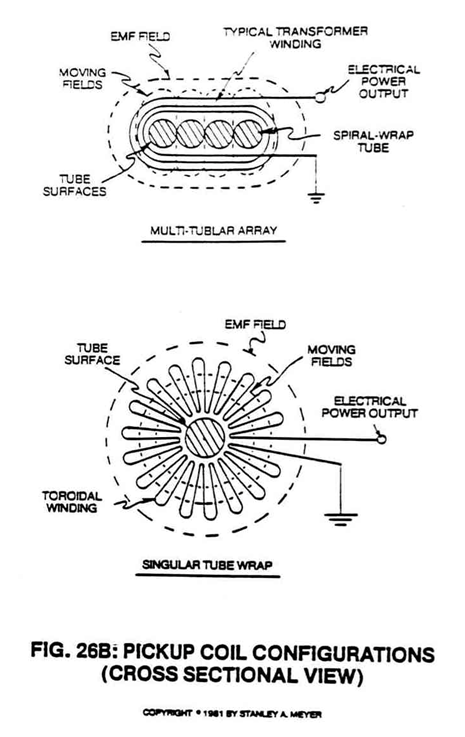
To cancel out magnetic field loss (magnetic flux lines not being used) during EPG operations, the "transformer" coil-wrap (Figure 26B) is used with the tubular spiral-wrap configuration of Figure 33.
The toroidal coil-wrap (also Figure 26B) is ideally suited for singular tube applications.
Other coil-wrap designs can be used for particular electrical needs.
In all cases, the pickup coils are placed end to end around the portion of the tube beyond the gas acceleration stage, as shown in Figures 26C, 27 through 29 and 33, to form a magnetic coupling of the EMF fields emanating away from the moving gas-field; see Figure 26B again.
 |
|
 |
 |
These concentric magnetic rings allow a magnetic field to pass inside another magnetic field without opposing forces since all of the magnetic flux lines are parallel to each other.
EPG: FLEXIBILITY OF POWER YIELD:
The EPG electrical power output is design-variable since the electrical generators can take on different sizes to meet a given power need.
If additional electrical power is required, simply increase the number of pickup coils.
If more amps are needed, connect the pickup coils in parallel.
If higher voltage is desired, connect the pickup coils in series arrangement.
If a given electrical power yield is contemplated, connect the pickup coils in a series/parallel arrangement to meet the electrical need.
Multi-phasing is simply accomplished by subdividing the coil network to provide proper electrical hookup.
Balance phasing is automatic since the gas velocity remains constant while passing through the entire array of pickup coils.
Pulse phasing of the electrical power output is accomplished by pre-arranging the pickup coils within an array. D.C. pulses occur when the coil arrays are of like turns. A.C. pulses are produced when pickup coils are directly linked to oppositely turned coils of similar design. AC/DC output occurs when both types of coil arrays are wrapped around the same tubular structure in a singular or multi-tier arrangement as shown in Figures 26C and 33.
And finally, to vary electrical power output without system change, simply vary gas velocity. To vary pulse rate output, vary the pulse rate input to the orientation coils.
EPG: MAGNETIC SPIN GENERATOR:
As an alternative to the moving gas approach, the EPG magnetic field spin generator simply rotates the permanently magnetized gas on it’s dyne-axis by pulsing alignment coils, as shown in Figure 30.
The variable pulse voltage frequency input directly determines the power output of the spin generator. Again, the power input into the spin generator is used to realign the permanently magnetized gas, not to produce the magnetic field of the gas.
EPG: OPERATIONAL PARMETERS:
Regardless of the type of EPG electrical generator, the electrical power output is determined by one, or several, or all of the following design parameters:
1) field strength of gas or particle under pressure;
2) gas velocity;
3) number of turns per coil;
4) number of coils;
5) number of tubular wraps per tier (see Figure 33);
6) magnetic field spin (horizontal to vertical deflection, rotational, and compressional wave; and
7) any and all combinations of the above.
The only purpose of the power input into the EPG electrical system is to move, rotate, cycle, and/or attenuate the magnetic field of the magnetically charged Particle-gas under pressure.
By climatizing the EPG system into a water-tight, pressure tight housing, the EPG system can be used on land, under the sea, or in the vacuum of space.
Gravitational forces have no appreciable effect on the operational performance of the EPG generator since the portable power unit is a closed loop system.
FUEL CELL LINKED TO EPG SYSTEMS:
Just as important, the fuel cell can be used to produce electrical energy in several different ways, as illustrated in the energy-grid system of Figure A and pictorially shown in water fuel cell of Figure
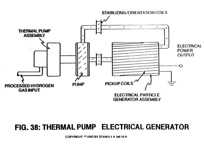
The "Q" pipe (or heat pipe) assembly simply transfers heat energy from the sustained hydrogen flame to the thermal gas pump of Figure 38 without any mechanical moving parts.
|
|
|

The quenching tube distributes the processed hydrogen gas to the gas-engine of Figure 37 without the aid of a gas pump.
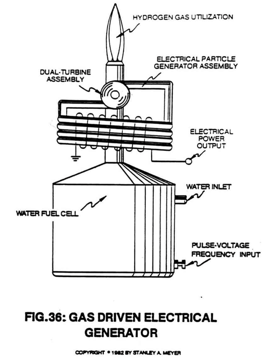
The gas flow pressure from the fuel cell turns the dual-turbine assembly of Figure 36 without altering the combustion property of the gas.
|
Figure 37
|
Figure 36
|
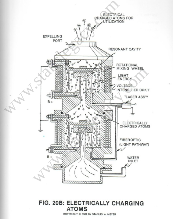
Finally, and most dynamic, the electrically charged atoms of Figure 20B are used in conjunction with the electrical polarization generator of Figure 40 prior to gas ignition.
|
|
|
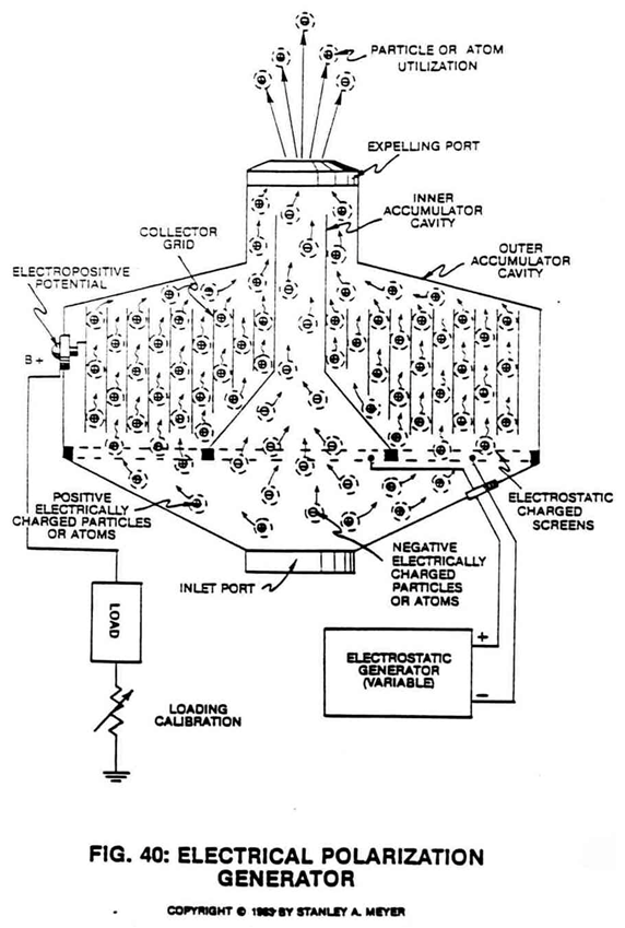
Whenever a gas powered electrical unit is connected to the EPG network of Figure A, the electrical system hookup is known as a regenerative energy feedback module, as illustrated in Figure B.
|
 |
Spin Off Technology
In almost all cases of scientific accomplishments, spin-off technology occurs. The Water Fuel Cell is no exception. For every cause there is a reason and for every reason there is an answer and for every answer there is progress. Without scientific progress, we cannot hope to cone with, nor solve, the energy needs of the world. The areas of development below are for that purpose and that purpose only.
TRANSMITTING HYDROGEN THROUGH CONVENTIONAL GAS LINES:
In the area of hydrogen distribution, the quenching circuit technology (see Figure 24) can be altered in a way as to allow hydrogen gas to be transmitted through a standard gas line safer than natural gas, as so illustrated in Figure 31.
This is accomplished in a three-step process.
First, the ambient air is converted into non-combustible gases (non-burnable gases having no oxygen atoms) when exposed to an open flame.
 |
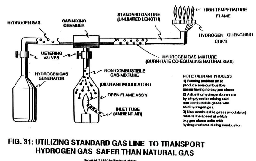 |
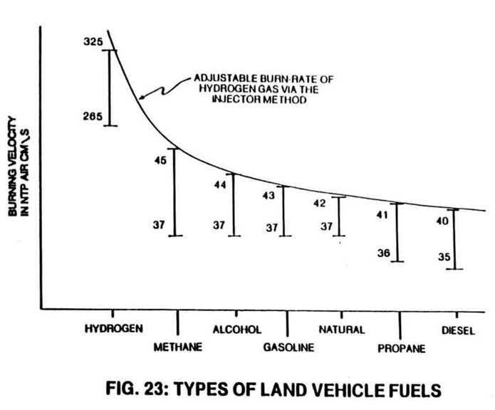 Secondly, the non-combustible gases are systematically mixed with the hydrogen gas to adjust the hydrogen burn rate to co-equal that of natural gas (see Figure 23).
Thirdly, the hydrogen flame is sustained and maintained since the non-combustible gases act as a modulator that retards the speed at which the oxygen atoms (obtained from ambient air) unite with the hydrogen atoms during the combustion process.
Economically, the air conversion cost is almost negligible when considering the fact that a small open flame can convert billions of cubic feet of ambient air (which is free) into non-combustible gases...and especially when the Water Fuel Cell can provide both the open flame as well as the hydrogen gas.
The processed hydrogen gas mixture requires no special handling requirements and can be injected into a conventional gas grid system without the aid of special connectors or other hardware.
STEAM RESONATOR:
 In the realm of steam power, the resonant cavity technique (see Figures 12, 17, 19 and 20) can be combined with the electrical charging of a single atom (one type) of a water molecule to produce superheated steam on demand, as shown in Figure 32.
As the incoming water molecule is exposed to the positive (b+) electrical voltage zone forming the resonant cavity vessel, the hydrogen atoms become positive (b+) electrically charged.
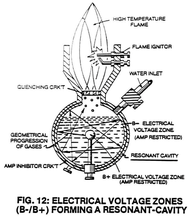 |
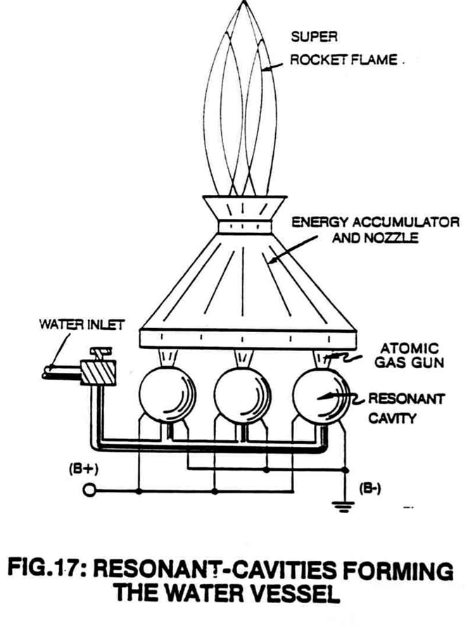 |
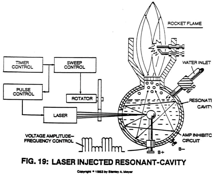 |
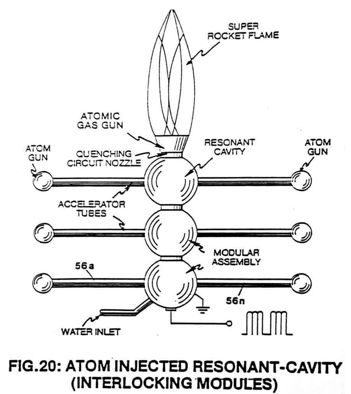 |
Since like charges repel and cause motion, the accelerated electrically charged molecule (b+ only) collides with the other water molecules, producing heat which is absorbed by the surrounding water.
Repetitive formation of the positive (b+) electrical voltage zones (see Figures 9A, 9B and 16) causes instant steam without consuming power in the form of amps.
To further increase steam yield, simply increase the amplitude of the applied pulse voltage frequency potential of a single polarity.
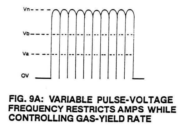 |
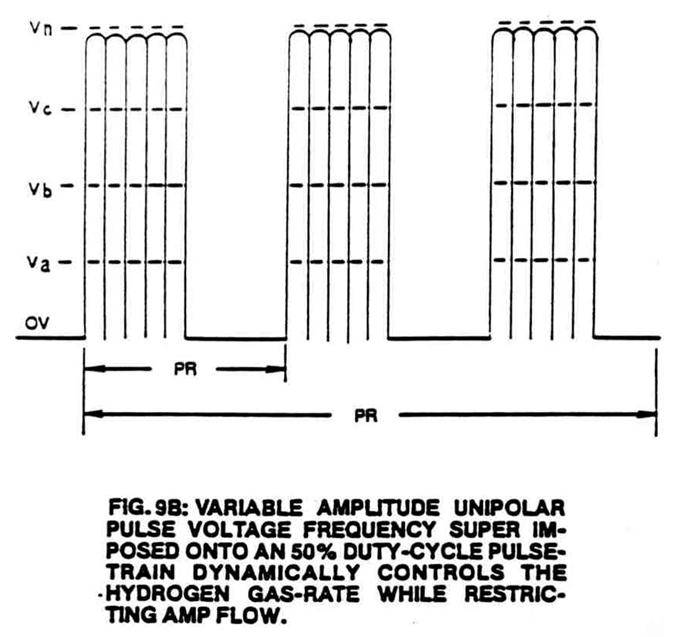 |
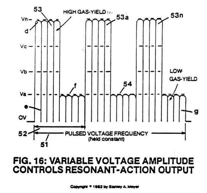 |
Linked with the EPG systems (Figures 26 through 30), or with the pulse voltage frequency generators shown in Figures 33 and 34, the steam resonator (Figure 32) can be directly retrofitted to any power plant using steam as power.
No fossil fuels or other burnable additives are needed in the process.
 |
 |
 |
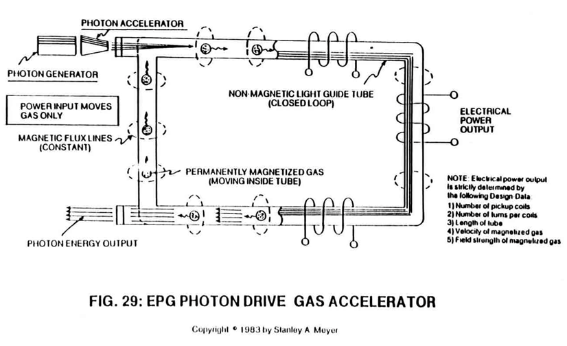 |
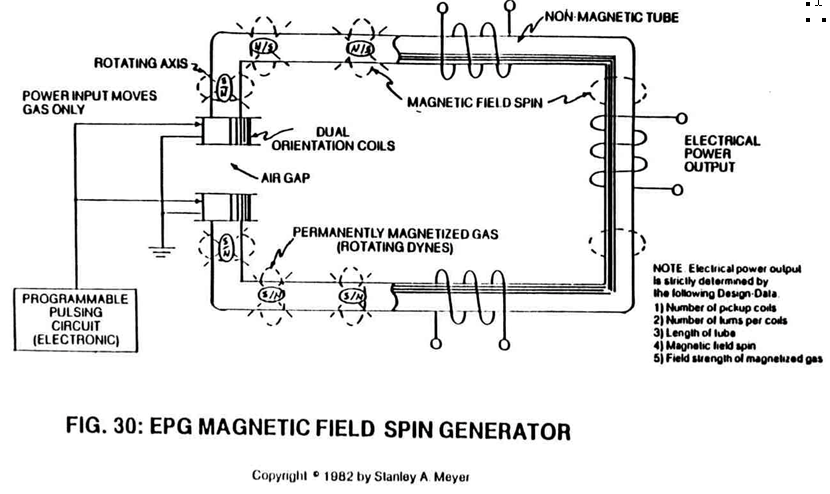 |
 |
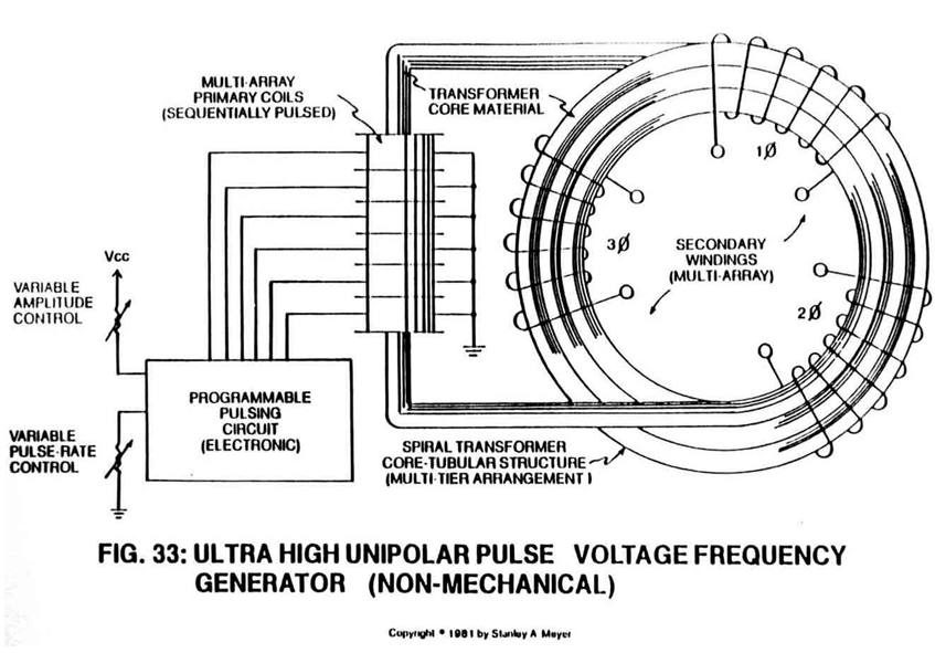 |
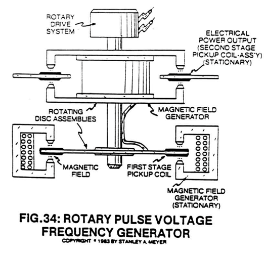 |
HIGH FREQUENCY PULSING GENERATOR:
In special areas of power applications, the non-mechanical pulse voltage frequency generator (See Figure 33) can be utilized where ultra high pulse frequency is needed without sacrificing lower yield.
The multi-array primary coils overcome the pulsing limitation of a single coil; whereas the spiral transformer core (hollow structure) reduces the magnetic field loss between the primary and secondary windings.
The multi-tier arrangement allows for multi-power applications.
To help maximize power loading efficiency, the spiral tubular core configuration (Figure 33) is also incorporated into the design of the EPG electrical system (Figures 26 through 30).
The spiral core configuration is also instrumental in providing balance phasing between any given number of pickup windings.
ELECTRICAL PULSE GENERATOR:
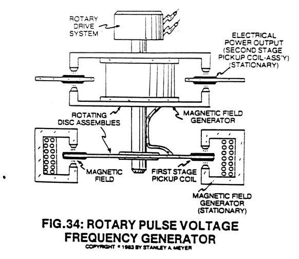
To further facilitate flexibility, the Electrical Pulse Generator (Figure 34) was primarily developed for special applications, such as for grain drying or for regenerative energy feedback systems.
The rotating first and second stage pickup coils allow the magnetic field strength of the first magnetic field circuit to be increased in the second magnetic circuit...
increasing power Output without the aid of contact brushes.
LIGHT GUIDE LENS ASSEMBLY:
S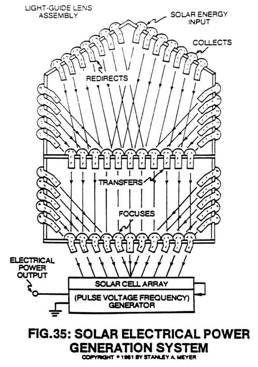 olar energy input into the energy grid system (Figure A) can be obtained by utilizing a Light Guide Lens Assembly, as shown in Figure 35.
The cylindrical "wall" lens, focusing and transfer lenses, and capping lens form a unitized silo structure that collects, redirects, transfers and focuses the light energy without any moving parts, regardless of the sun position during the daylight hours or seasons.
The concentrated solar energy can either be stored or converted into electrical energy by high-yield solar cells.
The solar lens operates on the fiber-optic principle.
GAS DRIVEN ELECTRICAL PARTICLE GENERATOR:
 Combining the Water Fuel Cell with the Electrical Particle Generator, as shown in Figure 36, further aids the energy grid system (Figure A) as to energy feedback by coupling a dual turbine wheel assembly to the quenching nozzle of the Fuel Cell.
As the gas is generated and expelled through the gas nozzle, the moving gas turns the first stage turbine, which drives the second stage turbine that propels the magnetized gas for electrical power generation.
This process does not convert the generated gases in any way...it only utilizes the pressure of the gas to perform work during Fuel Cell operations.
INTERNAL COMBUSTION ELECTRICAL GENERATOR:
Another regenerative energy feedback network is formed when the Electrical Particle Generator of Figure 37 is retrofitted to any type of internal combustion engine.
The engine mechanical drive train is affixed to the EPG turbine that propels the magnetized gas for electrical power generation.
Since the hydrogen gas burn rate co-equals gasoline, the engine gas-fuel is directly supplied by the Fuel Cell in Figure A.
This process simply utilizes the combustion property of hydrogen gas rather than the movement of the gas.
|
 |
THERMAL PUMP ELECTRICAL GENERATOR:
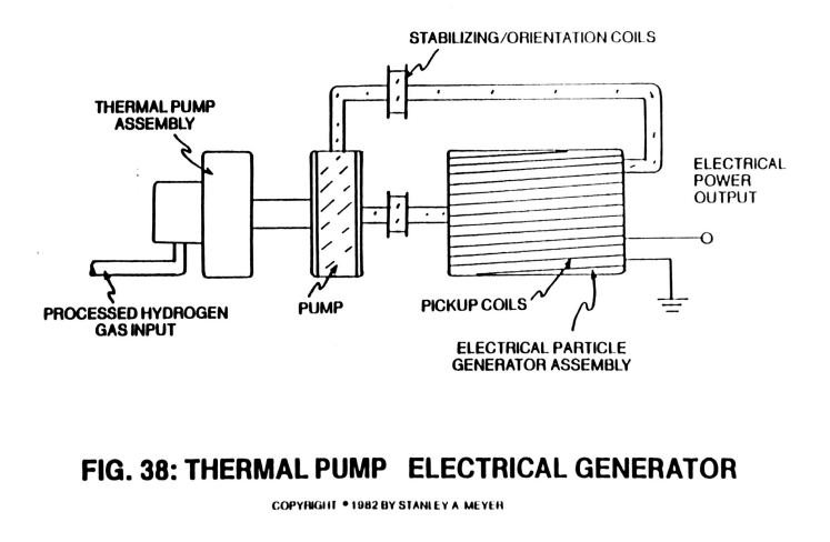
The Thermal Pump Electrical Particle Generator of Figure 38 operates on the third aspect of the hydrogen gas, which is heat.
The sustained hydrogen gas flame of Figure A provides the heat energy input to drive the thermal pump assembly, which in turn provides torque power to the EPG turbine assembly.
Beyond the gas conversion process, the EPG turbine assembly can be affixed to portable windmills or compressed air systems for EPG operations.
ELECTRICAL POLARIZATION GENERATOR:
 To complete regenerative energy grid of Figure A as to Water Fuel Cell of Figure B, the electrical polarization generator of Figure 40 is utilized to capitalize on the fourth aspect of a gas, which is gas ionization.
As illustrated, a stream or group of positive electrically charged atoms on a surface causes the collector-grid surface to be positive charged, which in turn makes the terminal post positive charged since said terminal post is affixed to said collector-grid.
As more charged atoms are entrapped within said collector-grid, said terminal potential increases until gas flow rate becomes constant.
Once an electrical load is placed between said positive terminal post and electrical ground and electric current-performs work as to load capacity.
The electrostatic charged screens attract more charged atoms continue the electrical performance of said generator.
In essence, said electrical polarization generator (Figure 40) requires no chemical interaction nor moving parts since the moving electrons combined with the moving charged atoms prior to secondary atom utilization beyond the expelling ports.
If required, negative electrical potential is generated by allowing negative electrically charged atoms to pass through the inner accumulator cavity.
HYDROGEN GAS RECLAIM SYSTEM: WATER PURIFICATION:
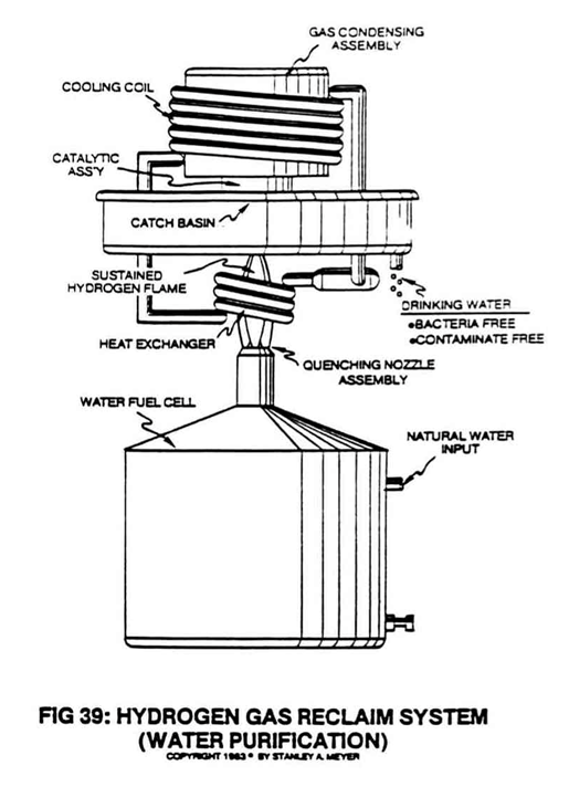 As explained in Section Six and as illustrated in Figure 39, the hydrogen gas reclaim system renders hydrogen environmentally safe.
In actuality, the reclaim system is a water purification system that has the capability of extracting both contaminants and bacteria from natural water without the aid of chemical additives or special filtration systems.
The water purification process is quite simple: the electrical polarization process splits the water molecule to form a gas mixture that sustains a hydrogen flame during combustion and produces water vapor.
Contaminants that are no longer stored between the splitting water molecule are systematically discarded from the Fuel Cell.
If any bacteria in water affix themselves onto the expelling gas the high temperature flame simply incinerates them.
The catalytic block assembly ensures the complete combustion of the hydrogen gas, and the catch basin simply collects drinking water free of all contaminants, bacteria and chemical toxicity.
This system is ideally suited for desalination of ocean water for desert irrigation. Mineral extraction from water is another application.
THE WATER FUEL CELL TECHNOLOGY ANSWERS THE QUESTION:
The Water Fuel Cell technology is a composite of many systems integrated together for a common purpose...
providing a practical answer to the energy problem.
The hydrogen age can now replace the fossil fuel era.
Ending Sections