WFC Technical Brief Extended - Design Specs
The Birth of New Technology, a.k.a The WFC Technical Brief, was a shortened/selected collection of the WFC Memos. Even then, only various memos have been available to the general public. A few more have been acquired through hard work and effort over the years. (423DA, 430-2, etc) In addition to the Birth, so existed an Extended Version of it containing sections of card photos, various demo cell exhibits, early driver circuits for the black box, and a set of Design Specs for each area of technology or device. In classic Stan, the references to Figures are sometimes incorrect. Most figures referenced are no where known, but this alone serves to prove we may have only seen the tip of the iceberg! - Chris
- Dual Voltage Attenuation Circuit
- Steam Resonator
- Electrical Particle Generator
- Electrical Polarization Generator
- Exhibits
Dual Voltage Attenuation Circuit
Resonant Cavity
N) Resonant Cavity:
PURPOSE: To enhance hydrogen gas production beyond voltage attenuation by way of compounding-action (particle impact)
Circuit Stage:
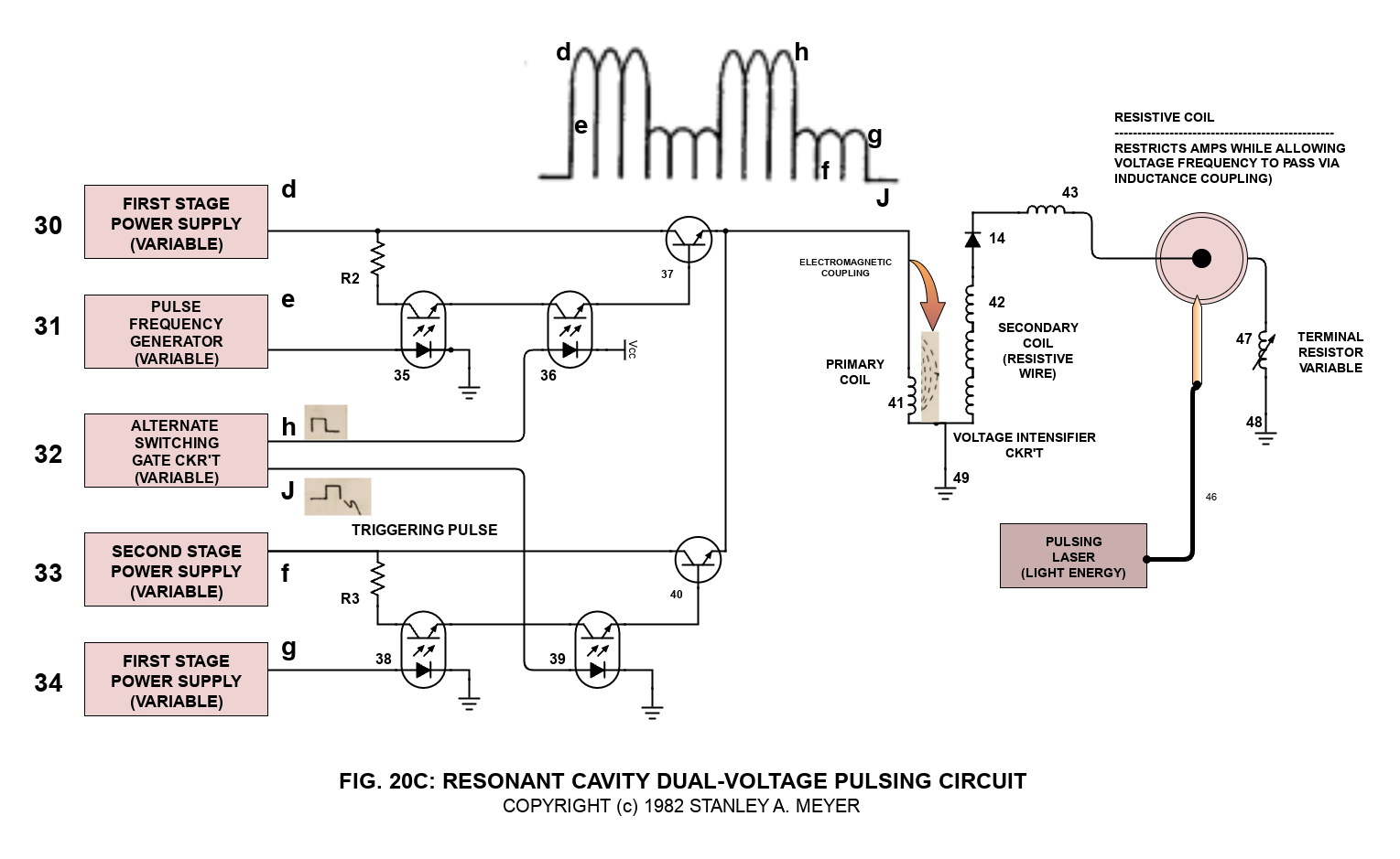
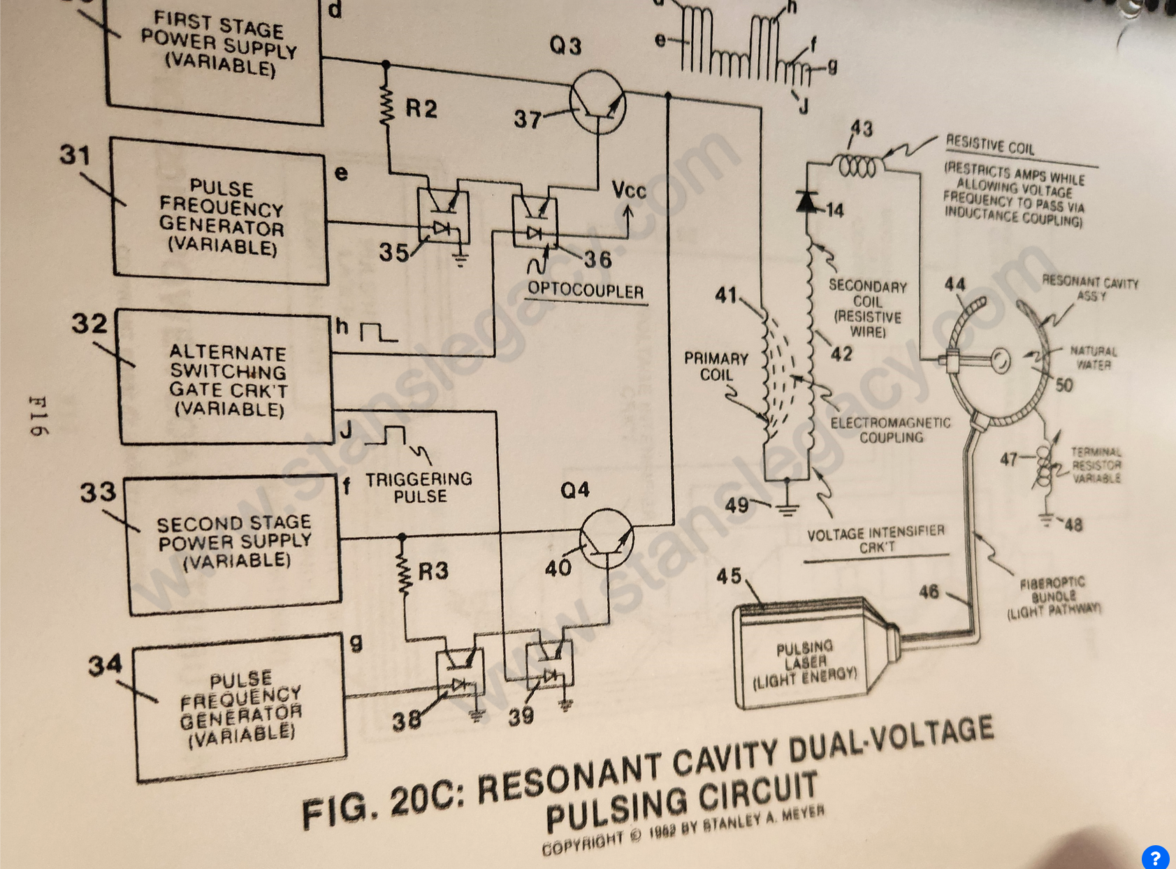
Integrating dual-pulsing circuit (33) (34) (38) (39) (40) to voltage intensifier circuit (Figure 9) previously described), as shown in Figure 20C.
 As shown in Figure 20C. variable gate circuit (32) is a two-state switch device which is directly linked to both opto-coupler (36) and opto-coupler (39).
As (H) near ground or low state (0 volts), opto-coupler (36) is triggered on. allowing pulse voltage frequency (d) as to (e) to form.
Once said gate circuit (32) changes state (low to high voltage or versa), trigger pulse (J) turns on opto-coupler (39) to form voltage wave form (f) as to (g).
Triggered pulse (H) is now terminated, switching off said wave form (d) (e).
Repeating said alternate gate switching produces dual-voltage pulse-train (51) of Figure (16).
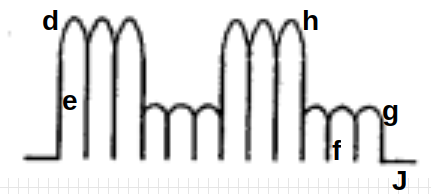 Wave form (d) (e) and wave form (f) (g) now pulse-duty (52) which is varied from one duty-pulse one hundred duty-pulses (establishing pulse-train 51) via gate circuit (32) (tenth and eleventh steps to voltage attenuation).
The reoccurring duty-pulse (52) is now attenuated to provide maximum gas-yield while minimizing amp flow.
This is accomplished in several ways:
1. Gated pulse (H) as to gated pulse (J) is proportionally changed to "concentrate" or "expand" said applied voltages to said resonant cavity. Said gated pulse train (53, on time) as to (54, off time) is adjustable from 1% to 100% duty time. As on-time (53) increases, off-time (54) proportionally decreases, allowing more voltage pulses (53) to be applied to said resonant cavity (44). To reduce the number of voltage pulses (53), simply reverse the pulse-train adjustment of said gate control circuit (32).
Once the gated pulse-train (51) is set as to maximizing gas production, the gated duty-cycle pulse (52) is now varied from one duty-pulse per second duration (52a) to one hundred duty-pulses per second duration (52n) to help restrict amp flow.
2. Said voltage amplitude (d) is varied to increase gas-yield. After said voltage amplitude (d) is stepped up, applied voltage range to said cavity (44) is from less than one volt to 5,000 volts or more.
3. Said voltage pulse frequency (e) is now varied from 1 Hz to 1 MHz and more, increasing gas-yield still further.
 Said voltage amplitude (f) is varied to sustain and compounding-action within said resonant cavity (44). Said voltage amplitude (f) is adjusted as to cavity-size. An increase in voltage amplitude (f) is required as cavity-size increases.
4. Once compounding-action is properly maintained, voltage amplitude (f) is adjusted "no" further to keep amp flow to a minimum (twelfth step to voltage attenuation and eleventh step to amp restriction).
Once step up, voltage range (f) is the same as voltage range (d), one volt to 5,000 volts or more.
Caution: Said voltage amplitude (d) should never be less than said voltage amplitude (f) in order to maintain said compounding action.
5. Said voltage pulse frequency (g) is now adjusted from 1 Hz to 1 MHz or more to reduce amp flow still further while maintaining said compounding-action.
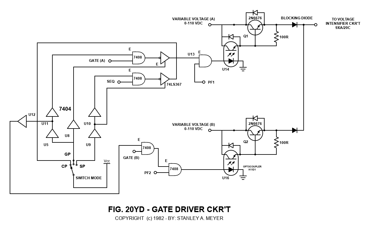
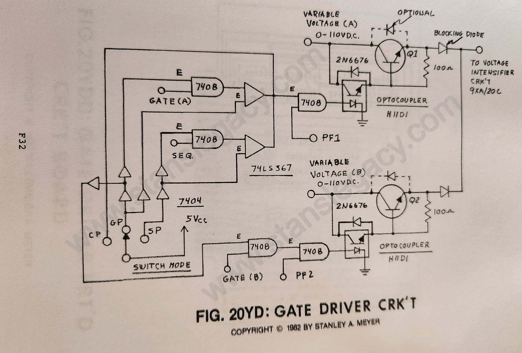
6. Said variable gate circuit (55) of Figure 20D is now retrofitted to said dual-pulsing circuit 20C to extend gas production beyond the limits of a single resonant cavity, keeping power loading to a minimum while adding another gas control feature.
7. As shown in Figure 20D, said resonant cavities are stacked exit port to inlet port to accelerate said compounding-action per stage.
8. Pulse-train (53) and pulse-train (54) can be of different pulse voltage frequency with different voltage amplitude adjustments, each pulse-train performing different functions. Pulse-train (53) regulates gas production on demand; whereas, pulse-train (54) maintains compounding action while restricting amp flow.
9. All above said voltage control features may be used separately, grouped together in sections, or adjusted in a systematic way to control said gas production on demand.
Circuit Function
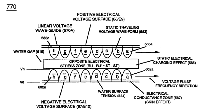
To form an oscillating voltage zone around another voltage zone of opposite polarity, forming a water gap therebetween.
Said voltage zones take on the shape of cavity-design due to the skin effect phenomenon as previously described.
Stainless steel T304 material is also used to form said resonant-cavity (44).
Said resonant cavity (44) can take on different shapes and sizes to meet a predetermined gas need. Spherical and longitudinal resonant cavities are examples.
To disassociate said water molecule by way of voltage stimulation as previously described. See Section A through Section M.
To momentarily entrap said liberated gas atoms to impart or subject a physical force (particle impact) on said water molecule being split apart. This process is called compounding-action or "resonant-action" since said liberated atoms are moved or oscillated in a uniform manner during gas production.
To start, sustain, and maintain said resonant-action during gas-yield attenuation.
To set up a variable pulsing circuit capable of "tuning-in" resonant action regardless of shape and dimensional size of said resonant cavity (44).
And to attenuate said voltage pulses (up to and beyond 5,000 volts) to cause said liberated gas atoms to reach ionization state.
Operational Comments
To start said compounding-action (resonant action) simply attenuate said voltage pulses while increasing said voltage amplitude.
Once resonant-action is established and said pulsing circuits adjusted for minimum amp flow, simply adjust said voltage amplitude controls to vary gas production and trigger gas ionization by way of particle collision
(see Exhibit BX, Encyclopedia of Chemistry, [Hampel/Hawley], Third Edition, Page 585).
O) Laser Injected Resonant Cavity:
PURPOSE: To enhance hydrogen gas-yield beyond said voltage parameters and said compounding-action (resonant-action) prior to gas ignition. And to help cause said liberated gas atoms to reach said state of gas ionization.
Circuit Stage: (45) (46) as to (44) in reference to said high intensity voltage pulse (53) (54) of Figure (16).
 |
|
Laser or light energy (45) of Figure 20C and Figure 20D is now injected into said high intensity voltage zones to help cause said liberated gas atoms (remember ambient air gases are also being released from said water) to reach said gas ionization state.
Said ionized gases enter into other resonant cavities (see Figure 20D as to Figure 20C again) in stacked relationship (exit port to inlet port) undergoing the same gas ionization process.
Ionized gas build-up per cavity-stage causes greater gas-yield to occur prior to gas-ignition or utilization.
Said laser or light energy is pulsed to maintain said compounding action within said resonant cavities.
The absorbed electromagnetic energy (light-energy) (45) by said atoms forming said water molecule also helps disrupt electrical mass equilibrium of said water molecule atoms when said water molecule atoms are subjected to said high-intensity voltage pulse (53) (54) of Figure (16). (See Exhibit BX again).
Laser assembly (45) can be any type of conventional laser that operates in the visible and/or ultraviolet region. In application, semiconductor lasers are used in packaged form to transmit said generated laser or light energy to said resonant cavity.
Said semiconductor laser package is variable pulsed from 1Hz to 1KHz or higher to help trigger gas ionization during said resonant-action process.
Resonant Cavity Mode of Operability
In scientific quantitative analysis (see Exhibit AX, McGraw-Hill Encyclopedia of Science and Technology, Volume 14, Page 489, and Exhibit BX, The Encyclopedia of Chemistry (Hampel/Hawley), Third Edition, Page 585), said water molecule is known to take on polar charges and that gas ionization can take place under certain conditions.
As herein described, said resonant-cavity fuel cell technology (see Water Fuel Cell Technical Brief in reference to Section A through Section M), simply encourages gas ionization (over and beyond prior art) of said water molecule atoms to increase gas-yield beyond said voltage attenuation prior to gas-ignition.
Gas ionization and utilization occurs in the following way:
-
Said water molecule (having polar charges as per Exhibit AX) is subjected to a high-intensity voltage pulse that separates said water molecule atoms by way of opposite polarity attraction law of physics, liberating hydrogen and oxygen gases from water. Ambient air gases dissolved in said water are also being released during said voltage process. Said fuel cell is a multi-gas generator.
-
As said liberated gases are exposed to a pulsating laser or light-emitting source (45), said liberated gases absorb said light radiation, causing many liberated gas atoms to lose electrons, said changed atoms now become positively charged ions. Said electromagnetically primed (atoms absorbed photon energy) hydrogen atom may now accept said liberated electron, forming a negative ion (see Exhibit BX).
-
In both cases, said formed ions are now subject to motion or deflection by said high-intensity voltage pulses (53/54). Compounding action (resonant action) now occurs since said ions' movements are directly related to said voltage pulse frequency. By simply increasing said pulse voltage frequency, said ions' movements increase. By decreasing said pulse voltage frequency, said ions' movements slow down. By keeping said pulse voltage frequency constant, said ions' movements remain constant. By increasing said voltage pulse amplitude, ion movement speeds up.
-
Since said ions are in motion, particle collision is now occurring when said ions' particles strike (physical impact or physical force) said water molecules undergoing said voltage separation, increasing said gas yield.
-
Particle collision also causes other liberated atoms to become ionized beyond the absorption of said light radiation, liberating more electrons inside said resonant cavity (44).
-
Since said liberated electrons have a negative electrical charge, said positive voltage pulse now causes said electrons to be moved uniformly with said pulse voltage frequency, aiding said compounding action (resonant action) still further.
-
To increase gas yield still further, said ionized or charged particles of gases are now injected into other resonant cavities undergoing above said resonant action process (see Figure 20D as to Figure 20C).
Geometrical gas production (Figures 13, 14, and 15) occurs when said resonant cavities are stacked exit port to inlet port or as a singular cavity unit. Said geometrical gas rate peaks out (or stops) when water flow rate into said resonant cavity becomes constant or reduced during gas production.
8. To increase and encourage greater particle collision (particle impact), accelerator tube (56) of Figure (20A) is placed between said resonant cavity stages (see Figure 20 and 20D).
 Said expelled charged gases (movement of gases between cavity units) move toward, through, and beyond oppositely electrically charged plates or voltage zones (57 of Figure 20A) which are periodically spaced inside said transfer tube (56).
By repeating said gas attraction process (20A) many times, said charged gas particles increase in velocity since sequential gate circuit (58) applies greater voltage potential per gas attraction stage (57).
Increasing particle velocity directly increases gas yield to the next resonant cavity stage. Adding more accelerator tubes (56a through 56n of Figure 20B) per resonant cavity stage (see Figure 20) increases gas yield still further (see Figure 20B again).
Varying gate switch circuit (58) is another way to control gas production on demand (fourteenth step to voltage attenuation).
Sequentially switching off and on accelerator tube array (56a through 56n) (parallel or series hookup) is another way to control gas production on demand (fifteenth step to voltage attenuation).
Figure 20A - Gas Accelerator Tube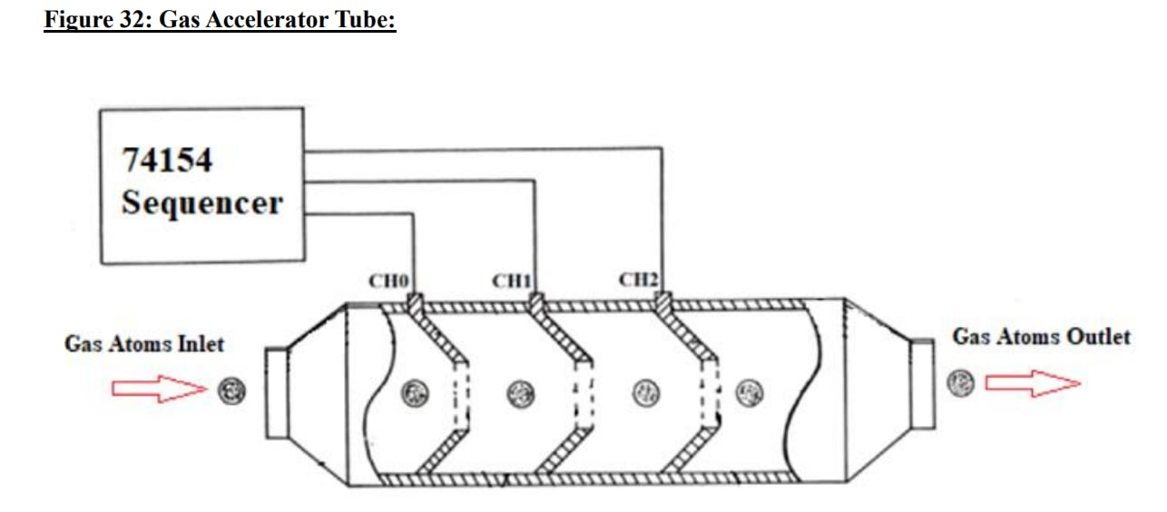
9. To prevent electrical discharge of said particles of gas when said resonant cavity (44) and said gas attraction zones (57) are submerged in natural water, said fuel cell housing is composed of an electrical insulating material such as plastic or spun glass.
Electrical positive and negative terminal surfaces are coated with an insulating material as shown in Figure 9D.
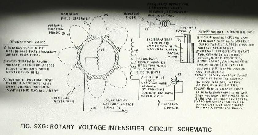
10. Said voltage intensifier circuit of Figure 9 as to Figure 9XA, Figure 9XF, and Figure 9XG are the same as Figure 20C, toroidal voltage intensifier circuit of Figure 20YG, and rotary voltage intensifier circuit of Figure 20YH, performing the same amp restricting/voltage attenuation functions as herein described.
The resonant cavity fuel cell can produce more than 115-cc/min of gases at one amp leakage.
Steam Resonator
Coming Soon!
Electrical Particle Generator
Coming Soon!
Electrical Polarization Generator
Coming Soon!
Exhibits
Exhibit BX1
EMERGING TECHNOLOGY
AMAZING LASER: Revolutionary new design of a widely used laser now combines miniature size and high power. This new type of semiconductor laser also offers unrivaled reliability and lower cost. It’s expected to have a broad range of applications—data processing, satellite communications, medicine, and, ultimately, computers that process information using light instead of electricity.
Background:
In the past 25 years, lasers have gone from an esoteric curiosity to one of today’s most important, versatile, and fastest-growing technologies. There are now dozens of different lasers—from low-power gas lasers used in eye surgery to powerful X-ray lasers expected to form the backbone of the Star Wars program.
The most commercially significant of all, however, is the semiconductor, or diode, laser. It's the workhorse of the electronics and telecommunications industries—used in compact disk players, fiber optic communications systems, etc. Diode lasers are prized for their compactness and high reliability. They resemble microchips and are made from the same semiconductor materials as chips.
Drawback:
The laser-on-a-chip is tricky to manufacture (tiny, faceted mirrors must be fabricated along its edges), and it produces only low-power beams.
Breakthrough:
New diode laser design produces beams many times more powerful than today’s models—out of the same size package. It’s also cheaper and less expensive to manufacture. Known as a surface-emitting diode laser, it uses its entire surface (not just the mirrored edge) to create a beam. A tiny grid, etched in the semiconductor material, precisely “tunes” emitted light into a single laser beam. This beam is more than 100 times more tightly focused than that produced by standard (edge-emitting) diode lasers.
Added advantages:
Because the new lasers eliminate the need for precisely machined and focused micro-mirrors, they’re also more reliable. In addition, surface-emitting diode lasers can be optically “locked” together to create a very high-power laser.
Status:
Commercial versions of the new laser should be available in one to two years.
Research leader: Jacob M. Hammer, Ph.D., RCA Laboratories, David Sarnoff Research Center, Princeton, NJ 08540.
YEAST—RISING IN A NEW WORLD:
Baker’s yeast—the same organism that has leavened bread and fermented wine for more than 6,000 years—is now beginning to make big payoffs in the world of biotechnology. It’s making genetic engineering easier, more productive, and more profitable for scientists and biotech and pharmaceutical firms.
Background:
Genetic engineering centers upon the ability to modify the genetic makeup of simple organisms. Scientists select an organism and insert DNA (genetic instructions) that corresponds to the production of a particular protein, thereby “commandeering” the organism to do their bio... (ends on this page).
© 1987 Boardroom Reports, Inc.